1. Introduction
Quadruped robots have been an important field in the research of bionic robots. In recent years, a number of researchers have developed various quadruped robots, such as Baby Elephant [
1], LS3 [
2], BigDog [
3], HyQ [
4], Cheetahcub [
5], LittleDog [
6], Tekken [
7], MIT Cheetah [
8], and many other quadruped robots.
In general, quadruped robots are often equipped with single rigid trunks, which are usually used as platforms to fix legs or carry electric boards, power sources, manipulators and other devices. As far as the authors know, the rigid trunks of quadruped robots rarely make active contributions to the motions of quadruped robots. However, natural quadrupeds all have moveable trunks, often used in their daily life. This is one of the biggest differences between traditional quadruped robots and natural quadrupeds. During the study of this difference, Dai, Zhang and Tang [
9,
10,
11] invented metamorphic robots which employed the metamorphic mechanisms as the trunks that could improve the quadruped robots’ locomotion performances in the workspace [
12], tumble stability [
13] and locomotion speeds [
14].
Obviously, jumping motion could be regarded as a part of the bounding gait. The bounding gait, which is a gait style of quadruped robots with large stride length and good obstacle avoidance ability, can greatly enhance the ability of robots to cross complex terrains. Due to its powerful functions, the bounding gait has received significant attention in the robotics community, starting from the work of Raibert [
15,
16] on dynamic legged robots and continuing with later studies on different platforms including KOLT [
17], Scout I and II [
18,
19]. Most of these bounding robots have single rigid trunks, four passively compliant legs, and are almost always equipped with individually actuated hips.
Some current researches have pointed out that the arching and pitching trunk of quadruped robots brings better bounding performances. A few researchers have emphasized on the effect of adding actuated and/or compliant degree of freedom (DOF) to the trunk segment. Some researchers verified their discoveries via simulation work. As one of the early works, Leeser [
20] explored the role of the trunk in fast running with a planar quadruped robot with an articulated trunk. He found that thrusting with the trunk could be used to augment the thrust provided by the legs and modify the impedance characteristics of the legs. Then, Kani and Ahmadabadi [
21] tested the effects of flexible trunk actuation on the bounding gait with a quadruped robot in four different cases studies. The results showed that by utilizing trunk actuation not only the speed of the locomotion increased considerably, but also the bounding power consumption was reduced. With similar tests, Pouya et al. [
22] found that active trunk control decreased energy efficiency and self-stability behavior of the quadruped robot, compared to that with passive compliant trunk.
In addition to simulation studies, researchers have recently tested a number of quadruped robots with actuated trunk joints. For instance, Folkertsma et al. [
23] showed that the use of parallel springs in a bounding quadruped robot with a flexible trunk could lower power consumption by over 50%. The effect of the control of a quadruped robot with active trunk versus that with fixed trunk in bound gait was studied by Khoramshahi and Spröwitz et al. [
24]. And this paper demonstrated that the active trunk led to faster locomotion, with less foot sliding on the ground, and a higher stability to go straight forward. Then, a quadruped robot solely actuated by its trunk actuation was introduced by Zhao et al. [
25]. The above examples show case studies of designing, simulating and testing quadruped robots with an articulated trunk joint.
Unlike most researches which have focused on the arching and pitching trunks, this paper investigates the expandable trunk and reveals its impacts on the jumping motion of the quadruped robot. This is inspired by the frog. The motion of frog trunk is the contracting-stretching rather than the arching and pitching action during jumping. Slow-motion photography shows that prior to jumping, the frog will put itself in a crouched position and stretch its hind legs [
26]. Then, the frog contracts its trunk to concentrate the power of its entire body. Next, it expands its trunk, launching into the air. Guided by the jumping process of the frog, this paper designs a jumping motion with expandable trunk for a metamorphic quadruped robot, called the Origaker II.
This paper is aimed at revealing the effect of the expandable trunk on the jumping speed and distance of the quadruped robot. In order to simulate the contracting-stretching motions with the expandable trunk, this paper develops a CAD model of the Origaker II. Next, the benefits of the expandable trunk are mathematically analyzed. Then, we set contrast simulations with the rigid trunk robot to verify the impacts of the expandable trunk on the jumping speed and distance.
The layout of this paper is as follows. In
Section 2, the jumping motion of the frog will be observed. In
Section 3, we will present the structure and the motion design of the Origaker II. In
Section 4, the effect of expandable trunk during jumping of the Origaker II will be analyzed. In
Section 5, the simulation of the metamorphic quadruped robot is to be illustrated and the contrast simulations between the Origaker II and the rigid trunk robot will be investigated. At last,
Section 6 will conclude the work.
2. Trunk Expansion of the Frog during the Jumping Motion
In order to imitate the jumping motion with the expandable trunk, the motions of frogs shall be observed firstly.
Figure 1 shows the process of jumping motion of the frog. As can be seen, the frog not only swings its legs but also expands its trunk during the jump. It can be found that there are four stages in the jumping motion of the frog.
Stage (a): The frog is in a crouched position and the trunk is contracted. This is the preparation stage of the jump.
Stage (b): The fore legs press on the ground, so that the head and tummy of the frog are into the air. The trunk begins expanding. And the frog can adjust the direction of jumping in this stage.
Stage (c): The hind legs pull back to the ground. The trunk of the frog gradually expands to release the energy. At last the frog jumps out in the preset direction.
Stage (d): Finally, the frog completely expands its trunk and jumps into the air finally.
During this jumping process, the trunk undergoes the expanding process. In our opinion, it can be inferred that this expanding process contributes to the better jumping performance of the frog. To verify this, the trunk of Origaker II is designed to satisfy this expanding process. There are numbers of mechanisms that can perform the expanding motion. In particular, it is simple for the deployable polyhedral mechanisms [
27] to do that. However, the controls and analyses of these spatial mechanisms are complicated. Finally, the planar 6-bar linkage is chosen as the trunk of the robot. There are two main reasons why this linkage is selected. First, this linkage can achieve the motion of expanding. Second, this linkage makes it easy to provide four symmetrical points to mount four legs. After the observation of trunk expansion of the frog, the robot and the jumping motion with expandable trunk will be designed.
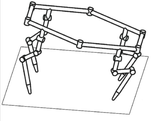
3. Design of the Expandable Trunk with Jumping Motion
The sketch of the robot is showed in
Figure 2. The lengths of links on the trunk are defined as
AF =
BC =
DC =
EF =
l1 +
l2 =
l and
AB =
DE =
l3. Where
l1 and
l2 represent the distances between the hip and the link joints. The hip joints are labeled with
Pi (
i = 1, 2, 3, 4). The offset distance from the center of each hip to the link on which it is mounted is labeled with
e. Every leg has three joints. The axes of leg joints are illustrated in
Figure 2 as
s1,
s2 and
s3. The
s1 is perpendicular to
s2 and
s2 is parallel to
s3. The lengths of leg links are represented by
d1,
d2,
d3 respectively. The plane which the planar 6-bar linkage lies on is defined as the trunk plane. The geometry parameters of the robot are set as shown in
Table 1.
As the planar 6-bar linkage has 3 degrees of freedom (DOF), joints
A,
E and
C are chosen as active joints to fully control the trunk. In order to perform the expanding motion during the robot jumps, these three angles should be restricted by the following equations.
Similar to the method of Zhang and Dai [
14], the hip location can be derived by the matrix transformation. The body coordinate system
O-xyz of the robot is established at the center of the link
AB, point
O, shown in
Figure 2, where the
z-axis is perpendicular to the plane of trunk, the
y-axis is perpendicular to the link
AB on the trunk plane and the
x-axis is determined by the right-hand rule. The hip locations will change as the trunk expands. For convenience, the expandable angle
θ is defined as the angle between the link
ED and link
DC, shown in the
Figure 2. The smaller the expandable angle
θ is, the more the trunk will contract. Thus, the coordinates of the hip locations can be derived by the method of matrix transformation.
Therefore, the transformation matrices T
i of the hip joints
Pi (
i = 1, 2, 3, 4) will be
where
T(
a,
b) represents translating along the axis
a by distance
b and
R(
α,
β) represents rotating about the axis
α by angle
β.
Hence the hip locations
Pi (
I = 1, 2, 3, 4) can be derived as below.
Every leg is a three-joint serial mechanism. It is simple to acquire the forward and inverse kinematics of this mechanism. Together with the hip locations, the integrated kinematics of the Origaker II is established. Next, the jumping motion will be designed.
With the planar 6-bar linkage as its trunk, the Origaker II can perform the jumping motion with expandable trunk like the frog. According to the frog jumping in
Figure 1, four similar stages are designed to implement the jumping motion, showed in
Figure 3.
Stage (a): The Origaker II contracts its trunk and legs. The expandable angle θ turns to 60°. This is the preparation stage of the jump.
Stage (b): The trunk stays contracting and the expandable angle θ keeps 60°. The front legs press on the ground, so that the Origaker II can adjust the angle between the trunk plane and the horizon plane.
Stage (c): The hind legs pull back to the ground. The trunk and hind legs of the Origaker II expands. The expandable angle θ rotates from 60° to 90°. The robot jumps out in the preset direction.
Stage (d): The Origaker II completely expands its trunk and hind legs and jumps into the air finally. The expandable angle θ stays 90°.
The analyses of the trunk motion follow the design of the jumping motion. Trunk motion brings more functions to the center of mass of the robot. Our purpose is to verify that the jumping motion of the Origaker II benefits from the trunk motion. Along with the trunk motion, the active joints in the trunk will provide the Origaker II with extra power, so that the robot can get a higher jumping speed and eventually a larger jumping distance. The effects of the trunk motion will be illustrated in
Section 4.
4. Effects of the Expandable Trunk on Jumping Motion
For general projectile motion, the distance of projectile depends on the Launching Velocity and direction. Similar to the general projectile motion, the jumping distance of the Origaker II is affected by the launching velocity and the elevation angle of trunk plane. A larger launching velocity will increase the jumping distance. And the jumping distance will benefit from a more appropriate elevation angle of trunk plane. The jumping height is another important index of the jumping motion and the initial kinetic energy is one of the determinants of the jumping height. Hence, in this section, the Launching Velocity, elevation angle of trunk plane and initial kinetic energy of the Origaker II will be analyzed.
As mentioned above, the trunk motion can enhance the jumping performances of the robot. For better contrast, we perform a comparison simulation between the Origaker II and the rigid trunk robot. The legs of the rigid trunk robot are the same as that of the Origaker II. The only difference is that the Origaker II has expandable trunk and the rigid trunk robot does not. Therefore, the effect caused by the four legs can be ignored.
The footholds before jumping of the rigid trunk robot are the same as that of the Origaker II. Under this configuration, the amplitude and orientation of the forces to the two robots provided by the ground can be the same.
4.1. Launching Velocity of the Origaker II
At any moment, the left and right legs perform the same actions. Therefore, the forces, velocities and accelerations provided by the left and right legs are all bilaterally symmetry.
The posture at the moment when the robot launches is shown in
Figure 4a. The trunk plane is represented by the plane Σ
1. The points
O3 and
O4 on the plane Σ
1 are the projections of hip joints
P3 and
P4. The COG (center of gravity) of the robot is expressed by the point
G on the plane Σ
1. The moving reference frame is established at point
O3. Therefore, the absolute velocity
vG of the point
G relative to the ground, that is velocity of the robot, can be obtained by adding vectorially the convected velocity
ve of the convected point
O3 and the relative velocity
vr of the particle
G with respect to the convected point
O3. That is
At the time when robot jumps, the left hind leg provides the velocity at O3 relative to the ground. That is ve.
Because the point
G is on the plane Σ
1, the velocity analysis is taken on the Σ
1, demonstrated in
Figure 4b. The velocities
vGp and
vep on the plane Σ
1 are the projections of
vG and
ve. A moving reference coordinate system
O3-
x3y3z3 is established at
O3, where
x3-axis is parallel to the link
DE and
y3-axis is perpendicular to the
x3-axis and the
z3-axis is determined by the right hand rule. The coordinate of point
G on this coordinate system is
where
θ is the expandable angle between link
CD and
x3-axis. After operating derivations of the point
G coordinate about time
t, the relative velocity
vr of
G with respect to the convected point
O3 can be derived as:
Therefore, velocity of the robot vG can be obtained by adding vectorially the convected velocity ve and the relative velocity vr. As Equation (12) shows, it can be found that the trunk motion provides a velocity component in the forward direction (y3-axis), l1cosθθ′. What’s more, a bigger angular velocity θ′ could increase this velocity component. The faster the trunk expands, the bigger forward velocity component is.
The longer
l1 will lead to the larger forward velocity. That means if we want a larger forward velocity, we can mount the hip joints nearer to the point
A,
B,
D and
E, respectively. That is consistent with the conclusion in [
14] about the effect of hip location on stride length.
For the rigid trunk robot, the forward velocities are only provided by the legs. In contrast, for the Origaker II, both the legs and trunk offer forward velocities when it jumps. The forward velocities of the Origaker II and the rigid trunk robot provided by the legs are the same based on motion design. Thus, an extra velocity component is added by the trunk motion of the Origaker II in the forward direction. This extra velocity increases the launching velocity compared with the rigid trunk robot. That is a significant effect of the trunk motion.
4.2. Trunk Plane Elevation Angle
At the moment when the front legs begin lifting but still remain on the ground, the postures of the Origaker II and the rigid trunk robot on the global coordinate system are shown in
Figure 5a,b, respectively. The jumping motions of the rigid trunk robot are designed according to that the four legs go through the same footholds as the Origaker II every time. Therefore, the footholds are coincide. At this moment, the trunk of the Origaker II is expanding but not expanding completely. The COG of the Origaker II and the rigid trunk robot are symbolized as point
G and
Gr, respectively. Under such motion design of the rigid trunk robot, the point
G is nearer to the origin
O of the global coordinate system than the point
Gr. That is
These two robots are kicking their front legs. The ground provides them a resultant counter-force
FF, along the blue line shown in
Figure 5. Assume that the two resultant counter-force
FF and the rotary inertias
I of these two robots are equivalent. The trunk planes of these two robots are equivalent at the initial posture. Therefore the elevation angle, between the trunk plane and the horizon plane, can be derived based the following equations. The sketch map of torques is shown in
Figure 5c. Where the middle of the front and the hind legs is symbolized as the point
P and point
Q, respectively. The foot point of
G and
Gr to line
PQ are represented by
H and
Hr, respectively. Thus,
where |
PHF|, |
PH| and |
PHr| are the moments of
FF,
G and
Gr, respectively. And the
β,
βr are the angular accelerations of the Origaker II and the rigid trunk robot. The gravities of two robots,
G and
Gr, are equal.
According to Equation (13) and the sketch map of torques, shown in
Figure 5c, it can be derived that:
It means that during the period when the Origaker II expands its trunk, with the assumption of the same rotary inertias, the angular acceleration of the rigid trunk robot is always larger than that of the Origaker II. The jumping motion is a very fast process, so that we suppose that these two robots undergo almost the same time t during the stage of lifting up the front legs. During this process, the average angular accelerations of the Origaker II and the rigid trunk robot are symbolized as and .
Therefore, the elevation angles of the two robots are
where the
φ and
φr represent the elevation angles between the horizon plane and the trunk planes of the Origaker II and the rigid trunk robot, respectively.
In order to ensure that the robots jump smoothly, the trunk plane elevation angles are always designed to be greater than 45°. The Origaker II gets a smaller elevation angle than the rigid trunk robot under the supposition of the same time t. The elevation angle of the Origaker II is neared to the optimum elevation angle, 45°, than that of the rigid trunk robot. So when the Origaker II jumps, it gets a larger forward velocity and a more appropriate elevation angle than that of the rigid trunk robot. These two help to increase the jumping distance. Thus the Origaker II has a better ability to cross the ditches. A vital effect of the trunk motion is to increase the jumping distance.
4.3. Kinetic Energy of the Origaker II
The kinetic energy is calculated by the dynamic method. Due to that the motions of legs of the two robots are the same, the dynamic analysis is focused on the trunk motion.
Figure 6 presents the mass of each link. Where the mass of the link
AB and
DE is symbolized as
m1, the mass of the link
BC and
DF is symbolized as
m2, the mass of the link
CD and
FA is symbolized as
m3 and the
θ expresses the generalized coordinates.
For every link, the kinetic energy could be calculated by the following formula.
where
mi is the mass of link
i,
vsi is the velocity of the center of mass of link
i,
Jsi represents the moment of inertia of the link
i relative to the center of mass and
ωsi means the angular velocity of link
i.
The sum of the kinetic energy of all the links could be calculated.
where
ω represents the angular velocity of
θ.
It is obvious that the kinetic energy increases with the length and the angular velocity of link
CD. The jumping stage starts at
θ =
θ1, and ends at
θ = 90°. Assume that the angular velocity
ω during the jumping stage is constant. According to the theorem of kinetic energy, the work which has done by the motors on the trunk is
The trunk work decreases with the increase of
θ1, shown in
Figure 7. Under the condition of the constant angular velocity, at the beginning of jumping stage, the smaller
θ1 leads to the bigger work. It means that the expandable trunk outputs more work because of the motion design of the smaller
θ1. However, if the
θ1 is too small, the front legs will run into the hind legs and the motion of robot might be ruined. After plenty of tests, the initial angle
θ1 is chosen as 60°, which ensures the correct motion of the Origaker II.
After the above analyses, it can be found that the expandable trunk can provide a greater speed, a better elevation angle and extra work so that the robot has a good jumping performance. On the contrary, these analyses also guide our structure design and motion design, such as the smaller initial angle θ1 and the hip joints farther from the COG.
5. Contrast Simulations of Jumping Motion of the Origaker II with and without Expandable Trunk
A CAD model was developed for the Origaker II and a simulation was carried out in Matlab and Adams with this model. In Adams, all the 15 degrees of freedom (DOF) of the trunk and four legs are under control by the motion splines designed in
Section 3. The friction between foot tips of the robot and the ground is set to Coulomb friction. The static and dynamic coefficients are 0.2 and 0.1, respectively.
Figure 8 shows the simulation in Adams, indicating that the Origaker II can successfully perform jumping motion. There is a simulation video of the jumping process in the
Supplementary Materials.
These pictures show the process of jumping motion designed in
Section 3. Firstly, the Origaker II contracts its trunk and legs into a ready posture. Then, this robot expands its front legs and trunk to adjust the direction of jumping. Next, the robot completely expands its trunk and hind legs, and jumps into the air. The system is non-holonomic in the flying mode but stable enough with friction performing little impacts on the results. Finally, it drops to the ground and slides a short distance. The motion after the robot drops on the ground is not designed. So the robot stays the posture in the air and slides a short distance to consume the remaining kinetic energy. This robot can correctly achieve the jumping motion of the frog.
The contact forces between the ground and four legs are shown in
Figure 9. The robot is over the ground at first. Then the robot lands on the ground firstly emerged that the peaks of the contact forces before the time
t = 0.5
s. Because of the jumping motion of the robot, there are other peaks near to the time 0.5
s. The robot jumps into the air at those peaks. Finally, the robot lands on the ground and this brings the peaks next to the time 1
s. This figure illustrates the process of the contact forces between the ground and legs.
To show more explicitly, a CAD model of the rigid trunk robot which is obtained by locking the joints of the expandable trunk has been developed. The robot without expandable trunk goes through the same footholds as the Origaker II. We also simulate its jumping motion in Adams, presented in
Figure 10. This robot jumps in a similar way of the Origaker II. Nevertheless, there are different performances between the two robots. In order to reveal these differences, the positions of COG in
y-axis and
z-axis are investigated firstly. The coordinates along
y-axis denote the jumping distance and the coordinates along
z-axis represent the jumping height.
Figure 11 points out the positions and velocities of the COG of the two robots from the PostProcessor in Adams. The red and blue lines indicate the positions of COG of the Origaker II and the rigid trunk robot (without the expandable trunk) respectively. The jumping performances of the two robots are similar in general tendency. As can be seen in
Figure 10a, at the time
t = 1
s when the robot lands on the ground, the jumping distance (excluding the sliding distance) of the Origaker II with expandable trunk is about 150 mm larger than that of the rigid trunk robot. It is further inferred that the Origaker II has a larger kinetic energy profited from the expandable trunk. This confirms that the trunk motion increases the jumping distance.
On the contrary, it is unexpected that the rigid trunk robot jumps higher than the Origaker II, shown in
Figure 11b. It is a main possible reason that although the Origaker II gets a bigger forward velocity than the rigid trunk robot, the trunk elevation angle of the rigid trunk robot is bigger. The bigger elevation angle contributes to the greater vertical velocity component. Thus, the jumping height of the rigid trunk robot is larger than that of the Origaker II.
As can be seen in
Figure 11c, the forward velocity of the Origaker II is 0.48 m/s, larger than that of the rigid trunk robot, 0.3 m/s. This is consistent with the
Figure 11a, because the slope of the two lines demonstrates the velocities of the robots. Obviously, the red line is more precipitous than the blue line. The upward velocities of two robots pass by almost the same trajectory, presented in
Figure 11d. The expandable trunk reduces the jumping height but it has little effect of the upward velocity. It is further inferred that the expandable trunk could increase the motion velocity.
These analyses and the simulations have verified that the trunk motion could increase the jumping distance and speed. This may greatly enhance the potentiality of robots to cross complex terrains, especially the ditches.
6. Conclusions
In order to reveal the impacts of trunk motion on the jumping motion of quadruped robots, this paper proposed a metamorphic quadruped robot with an expandable trunk, which could imitate the natural quadruped to expand its trunk when jumping, called the Origaker II.
By observing the motions of a frog during its jumping process, this paper summarized the process of the jumping motion of the frog. Following that, the structure design of the Origaker II was introduced. Inspired by the frog jumping, the series of jumping motions with the expandable trunk for the Origaker II was designed. Based on the theorem for the composition of velocities, the principle of mechanics and the theorem of kinetic energy, the effects of the expandable trunk on the velocities, elevation angles and the kinetic energy of the robot were analyzed. In this process, some assumptions were made to simplify the system. There is a good possibility that the results could be reliable. A simulation was carried out to show the performances of the jumping motion. With friction set in Adams, the robot was holonomic before jumping into the air. Even though the system was non-holonomic in the flying mode, it was stable enough performing no impacts on the results. Finally, we set contrast simulations utilizing a single rigid trunk robot to find how the expandable trunk enhanced the jumping performances. The results showed that the expandable trunk helped to increase the jumping speed in the air of the quadruped robot. This allowed that the quadruped robot achieves a larger jumping distance. The jumping speed and distance of the robot increased, benefited from the expandable trunk.
Author Contributions
The individual contributions of authors: conceptualization, J.S.D. and C.Z.; methodology, C.Z.; software, S.W.; validation, T.L., C.Z. and J.S.D.; formal analysis, T.L.; investigation, C.Z.; resources, J.S.D.; data curation, T.L.; writing—original draft preparation, T.L.; writing—review and editing, C.Z. and J.S.D.; supervision, J.S.D.; project administration, J.S.D.; funding acquisition, J.S.D.
Funding
This research was funded by the Natural Science Foundation of China (Project No. 51535008, 51721003) and the Programme of International Collaboration (“111 Program”) under Grant No. B16034.
Acknowledgments
The authors are grateful to the Centre for Advanced Mechanisms and Robotics of Tianjin University, for providing research opportunity and financial support.
Conflicts of Interest
The authors declare no conflicts of interest.
References
- Fukuoka, Y.; Kimura, H.; Cohen, A.H. Adaptive dynamic walking of a quadruped robot on irregular terrain based on biological concepts. Int. J. Robot. Res. 2003, 22, 187–202. [Google Scholar] [CrossRef]
- De Santos, P.G.; Garcia, E.; Estremera, J. Quadrupedal Locomotion: An Introduction to the Control of Four-Legged Robots; Springer Science & Business Media: London, UK, 2007. [Google Scholar]
- Bloss, R. Robot walks on all four legs and carries a heavy load. Ind. Robot Int. J. 2012, 39. [Google Scholar] [CrossRef]
- Boaventura, T.; Medrano-Cerda, G.A.; Semini, C.; Buchli, J.; Caldwell, D.G. Stability and performance of the compliance controller of the quadruped robot HyQ. In Proceedings of the 2013 IEEE/RSJ International Conference on Intelligent Robots and Systems, Tokyo, Japan, 3–7 November 2013; pp. 1458–1464. [Google Scholar]
- Chen, X.; Gao, F.; Qi, C.; Tian, X.H.; Zhang, J.Q. Spring parameters design for the new hydraulic actuated quadruped robot. J. Mech. Robot. 2014, 6, 021003. [Google Scholar] [CrossRef]
- Baisch, A.T.; Ozcan, O.; Goldberg, B.; Ithier, D.; Wood, R.J. High speed locomotion for a quadrupedal microrobot. Int. J. Robot. Res. 2014, 33, 1063–1082. [Google Scholar] [CrossRef]
- Chan, C.Y.; Liu, Y.C. Towards a walking, turning, and jumping quadruped robot with compliant mechanisms. In Proceedings of the IEEE International Conference on Advanced Intelligent Mechatronics, Banff, AB, Canada, 12–15 July 2016; pp. 614–620. [Google Scholar]
- Hodgins, J.K.; Raibert, M.N. Adjusting step length for rough terrain locomotion. IEEE Trans. Robot. Autom. 1991, 7, 289–298. [Google Scholar] [CrossRef]
- Zhen, W.; Kang, X.; Zhang, X.; Dai, J. Gait Planning of a Novel Metamorphic Quadruped Robot. J. Mech. Eng. 2016, 52, 26–33. [Google Scholar] [CrossRef]
- Tang, Z.; Qi, P.; Dai, J. Mechanism design of a biomimetic quadruped robot. Ind. Robot Int. J. 2017, 44, 512–520. [Google Scholar] [CrossRef]
- Zhao, X.; Kang, X.; Dai, J. Gait planning and motion characteristic analysis of a metamorphic quadruped walking robot. J. Cent. South Univ. (Sci. Technol.) 2018, 44, 2168–2177. [Google Scholar]
- Zhang, C.; Wang, X.; Wang, X.; Dai, J.S. Modeling for a metamorphic quadruped robot with a twisting trunk: Kinematic and workspace. In Proceedings of the IECON 2017—43rd Annual Conference of the IEEE Industrial Electronics Society, Beijing, China, 29 October–1 November 2017; pp. 6886–6892. [Google Scholar]
- Zhang, C.; Chai, X.; Dai, J.S. Preventing Tumbling with a Twisting Trunk for the Quadruped Robot: Origaker I. In Proceedings of the ASME 2018 International Design Engineering Technical Conferences and Computers and Information in Engineering Conference, Quebec City, QC, Canada, 26–29 August 2018; p. V05BT07A010. [Google Scholar]
- Zhang, C.; Dai, J.S. Continuous Static Gait with Twisting Trunk of a Metamorphic Quadruped Robot. Mech. Sci. 2018, 9, 1–14. [Google Scholar] [CrossRef]
- Raibert, M.H. Legged Robots That Balance; MIT Press: Cambridge, MA, USA, 1986. [Google Scholar]
- Raibert, M.H. Trotting, pacing and bounding by a quadruped robot. J. Biomech. 1990, 23, 79–98. [Google Scholar] [CrossRef]
- Estremera, J.; Waldron, K.J. Thrust control, stabilization and energetics of a quadruped running robot. Int. J. Robot. Res. 2008, 27, 1135–1151. [Google Scholar] [CrossRef]
- Poulakakis, I.; Smith, J.A.; Buehler, M. Modeling and experiments of untethered quadrupedal running with a bounding gait: The Scout II robot. Int. J. Robot. Res. 2005, 24, 239–256. [Google Scholar] [CrossRef]
- Smith, J.A.; Sharf, I.; Trentini, M. Bounding gait in a hybrid wheeled-leg robot. In Proceedings of the 2006 IEEE/RSJ International Conference on Intelligent Robots and Systems, Beijing, China, 9–15 October 2006; pp. 5750–5755. [Google Scholar]
- Leeser, K.F. Locomotion Experiments on a Planar Quadruped Robot with Articulated Spine. Ph.D. Thesis, Massachusetts Institute of Technology, Cambridge, MA, USA, 1996. [Google Scholar]
- Kani, M.H.H.; Nili Ahmadabadi, M. Comparing effects of rigid, flexible, and actuated series-elastic spines on bounding gait of quadruped robots. In Proceedings of the 2013 First RSI/ISM International Conference on Robotics and Mechatronics (ICRoM), Tehran, Iran, 13–15 February 2013; pp. 282–287. [Google Scholar]
- Pouya, S.; Khodabakhsh, M.; Spröwitz, A.; Ijspeert, A. Spinal joint compliance and actuation in a simulated bounding quadruped robot. Auton. Robots 2017, 41, 437–452. [Google Scholar] [CrossRef]
- Folkertsma, G.A.; Kim, S.; Stramigioli, S. Parallel stiffness in a bounding quadruped with flexible spine. In Proceedings of the 2012 IEEE/RSJ International Conference on Intelligent Robots and Systems, Vilamoura-Algarve, Portugal, 7–12 October 2012; pp. 2210–2215. [Google Scholar]
- Khoramshahi, M.; Sprowitz, A.; Tuleu, A.; Ahmadabadi, M.N.; Ijspeert, A.J. Benefits of an active spine supported bounding locomotion with a small compliant quadruped robot. In Proceedings of the 2013 IEEE International Conference on Robotics and Automation, Karlsruhe, Germany, 6–10 May 2013; pp. 3329–3334. [Google Scholar]
- Zhao, Q.; Nakajima, K.; Sumioka, H.; Yu, X.; Pfeifer, R. Embodiment enables the spinal engine in quadruped robot locomotion. In Proceedings of the 2012 IEEE/RSJ International Conference on Intelligent Robots and Systems, Vilamoura-Algarve, Portugal, 7–12 October 2012; pp. 2449–2456. [Google Scholar]
- Wikipedia Contributors. “Frog.” Wikipedia. Available online: https://en.wikipedia.org/wiki/Frog (accessed on 25 July 2018).
- Wei, G.; Chen, Y.; Dai, J.S. Synthesis, Mobility, and Multifurcation of Deployable Polyhedral Mechanisms with Radially Reciprocating Motion. J. Mech. Des. 2014, 136, 091003. [Google Scholar] [CrossRef]
© 2019 by the authors. Licensee MDPI, Basel, Switzerland. This article is an open access article distributed under the terms and conditions of the Creative Commons Attribution (CC BY) license (http://creativecommons.org/licenses/by/4.0/).


