Article

The Development of a Soft Robot Hand with Pin-Array Structure

1
State Key Laboratory of Tribology, Tsinghua University, Beijing 100084, China
2
Key Laboratory for Advanced Materials Processing Technology (MOE), Tsinghua University, Beijing 100084, China
3
Dept. of Mechanical Engineering, Tsinghua University, Beijing 100084, China
*
Author to whom correspondence should be addressed.
Appl. Sci. 2019, 9(5), 1011; https://doi.org/10.3390/app9051011
Submission received: 20 February 2019 / Revised: 5 March 2019 / Accepted: 6 March 2019 / Published: 11 March 2019
(This article belongs to the Special Issue Soft Robotics: New Design, Control, and Application)

Abstract

:

Featured Application

The CTSA-II hand developed in this paper can be used to grab objects, especially in places where general grabbing is required, such as industrial production lines, service robots, etc.

Abstract

This paper proposes a soft robot hand with pin-array structure and self-adaptive function, CTSA-II hand, where CTSA is the Cluster tube self-adaption. The CTSA-II hand is designed with a quite concise structure and consists of bases, a pin array, a spring array, and a membrane. When the CTSA-II hand grasps an object, the pins will slide along the trajectory to conform to the profile of the object under the reaction force applied by the object, and thus the outer membrane will form a specific shape, and then the vacuum drives the CTSA-II hand to grasp the object. Theoretical analysis shows that the CTSA-II hand can generate enough grasping force and get good stability. Moreover, the optimization of its structure is achieved by studying the effects of specific parameters. The capture experimental results of the prototype show that the CTSA-II hand can realize self-adaptive grasping of different sizes and shapes with a high degree of fit and a high success rate. A series of research experiments show the influence of various factors on the grasping force, which verifies the results of the theoretical analysis with the CTSA-II hand. Compared to the traditional robot hand, the CTSA-II hand has good crawl performance, concise structure, small volume, and easy assembly.

1. Introduction

As one of the mediums for robots to interact with the outside world, robot hands have an important role and certain value for the research. Traditional robot hands can be divided into three main types: industrial grippers, dexterous robot hands, and underactuated robot hands.
(1)
Industrial grippers are designed for the purpose of simplicity, safety, and low cost. Usually, there are several parts that can move relative to each other, such as MPG gripper [1] and MPZ gripper [2] developed by the SCHUNK. In addition, some industrial grippers use electromagnets and suction cups to achieve the function of grasping. However, this kind of gripper has the disadvantage of a single function, and a particular type of gripper can only be used on a particular type of production line.
(2)
The dexterous robot hands are designed to mimic the structure of the human hand and are designed to have multiple fingers. Salibury [3] defines the dexterous robot hand like a robot hand with more than 3 fingers and more than 9 degrees of freedoms (DOFs). Common dexterous hands, such as Utah/MIT hand [4], Gifu hand [5,6,7], and shadow hand [8], mimic the structure of the human hand and can perform complex operations, but they bring complex drive systems and control systems, as well as high costs.
(3)
In order to solve the high-cost problem of the dexterous hand, the underactuated robot hand is proposed. The underdrive means that the number of driving sources is smaller than the DOFs of the robot hand. From the existing research, the underactuated robot hand can be roughly divided into two parts, one is with obvious finger structure and the other is without obvious finger structure. This paper mainly studies on the underactuated robot hand.
Underactuated robot hands with distinct fingers structure include both rigid and flexible types. The rigid underactuated robot hands mainly use the combination of mechanical structure and reins or springs to achieve underdrive, such as SDM robot hand [9], FRH-4 hand [10], the hand developed by Shanghai Jiaotong University [11], TH-3R hand [12], and PASA hand [13]. The flexible underactuated robot hands tend to have more flexible adaptability, such as the soft hand developed by Raphael Deimel [14], OS Hand [15], Soft Grippers [16] developed by Miron et al., and Gripper [17] developed by Slesarenko et al. These multi-finger underactuated hands have a good effect on reducing costs and reducing the difficulty of the control system.
Only from the perspective of achieving more reliable performance of self-adaptive crawling, some underactuated hands without obvious finger structure have been proposed, such as the universal gripper based on the jamming of granular material [18], the universal gripper using mrα fluid [19], the SSA gripper [20], and the FlexShapeGripper developed by FESTO [21]. This type of underactuated hand has reliable gripping performance, low cost, and simple control, and has excellent performance. Therefore, this paper aims to develop a new type of underactuated robot hand.
Scott proposed a universal gripper named Omnigripper [22], as shown in Figure 1. The Omnigripper consists of a number of slidable pins that can slide up and down. These pins are divided into two sets, one is the left set, and the other is the right set. When grasping objects, the two sets of pins adapt to the shape of the object from the vertical direction, and then the two sets of pins move toward each other along a line, which provides a clamping force for gripping.
The gripping method of omnigripper has an excellent self-adaptive ability, but since the pins move only along a straight line, the omnigripper can only provide a grasping force from one direction, and cannot provide a grasping force when grabbing certain objects. For example, in Figure 2, the long object A, and the object C covered by only one set of pins cannot be crawled by omnigripper.
Although there are still some shortcomings in the grasping performance, the omnigripper puts forward the idea of adaption to the shape of the object relying on the slidable pins. Many scholars have designed robot hands [23,24,25] based on this structure, but they have strong uniqueness in grasping. For example, the gripper in [23] is mainly for objects with smooth and continuous curved surfaces, and the grippers in [24,25] are mainly for the objects with rough surfaces, especially rocks.
Inspired by the principle of slide pins, this paper will develop a robot hand with wider versatility.
The paper is organized as follows. Section 2 presents a new type of grasping mode, cluster-tube self-adaptive (CTSA) grasping mode. Section 3 presents the structural design of the CTSA-II hand. Section 4 presents the grasping force and crawl stability analysis of the CTSA-II hand. Section 5 presents the prototype and experiments of the CTSA-II hand. Conclusions and future work are presented in Section 6.

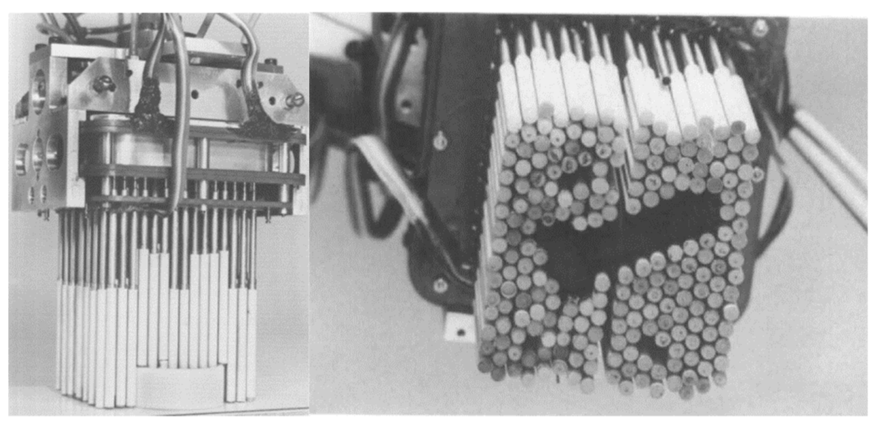
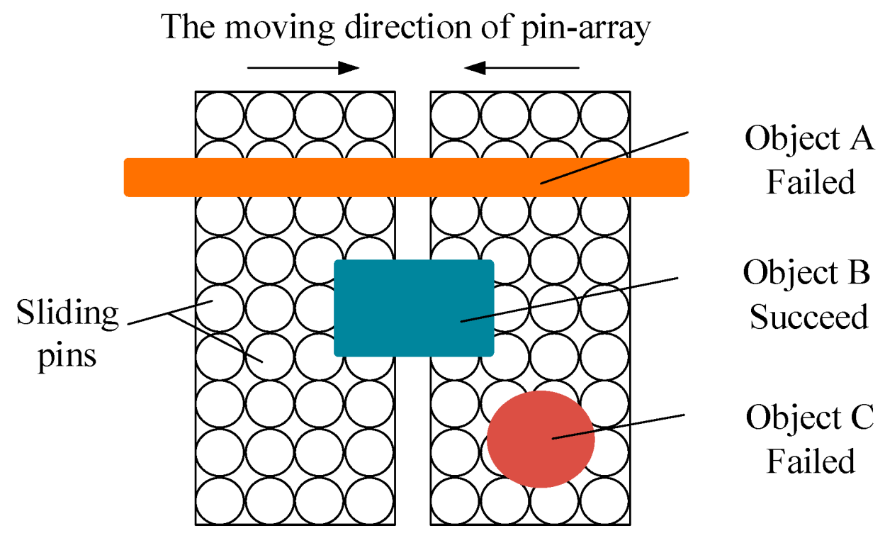
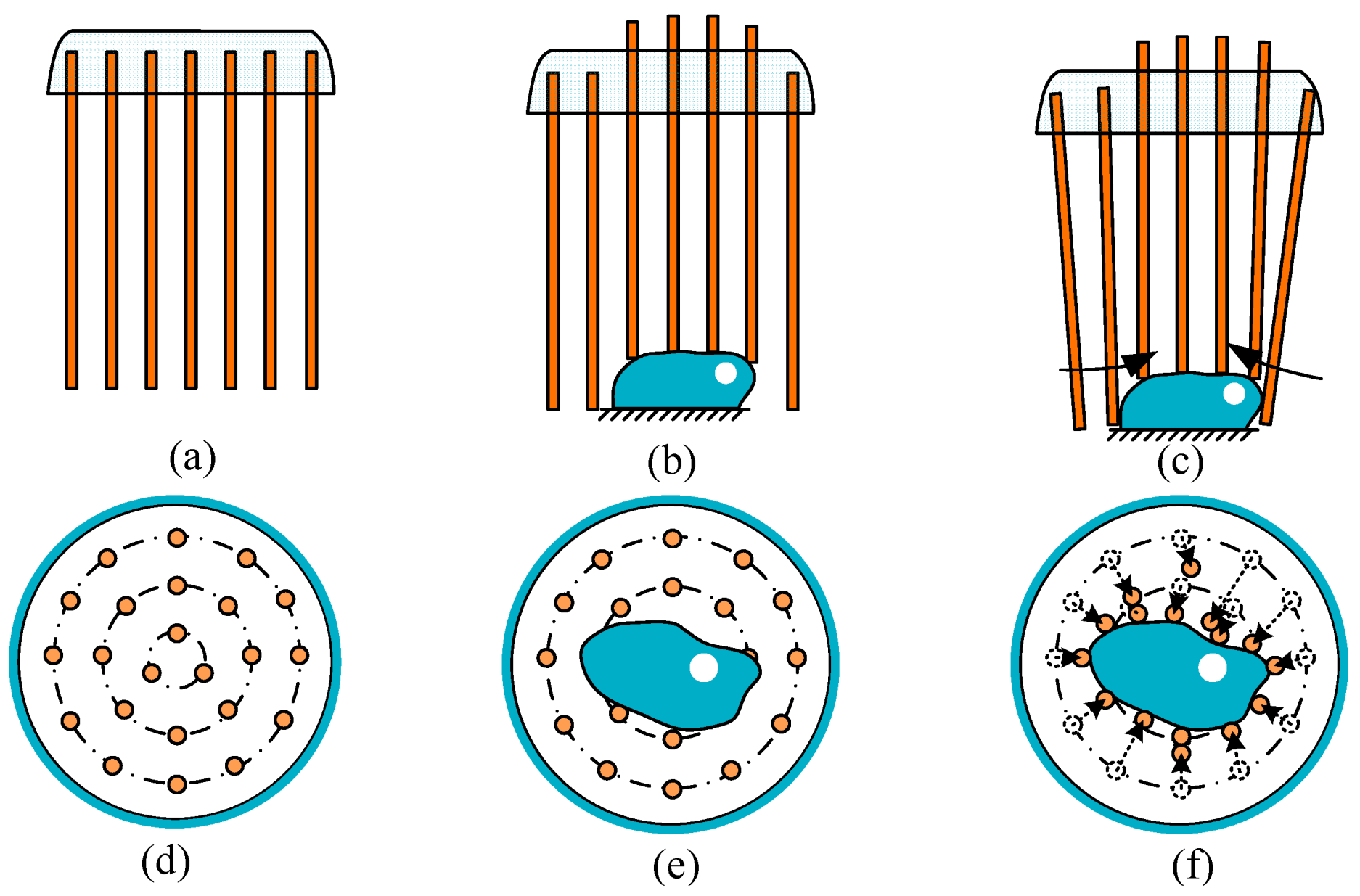
2. The Cluster-Tube Self-Adaptive Grasping Mode

In the introduction of Section 1, the gripping performance of the traditional robot hands has their own advantages and disadvantages. The robot hand adopting the slidable pins has good adaptability, but the application range is small. Therefore, this paper proposes a more universal grasping mode based on the adaptability of the slidable pins, which is the cluster tube self-adaptive mode, the CTSA mode.
The CTSA grasping mode is described as follows: All pins are distributed around the hand when not working, as shown in Figure 3a,d. When grasping object, different pins slide to different extends according to the shape of the object, making the hand to adapt to the shape of the object, as shown in Figure 3b,e. After that, the robot hand gathers all pins to the center of the object to provide a grasping force, as shown in Figure 3c,f.
The CTSA mode has outstanding advantages: (1) Through the structure of pin array, the shape and size of the object can be easily adapted from the vertical direction. (2) Because the pins are gathered from multi-direction when grasping, which can achieve the effect of providing a gripping force in multiple directions without missing omissions. (3) Any two pins can form a two-finger gripper when working, which means that it has a variety of suitable gripping gestures when grabbing an object, and it also means that multiple objects can be grabbed at the same time. Therefore, the CTSA mode is worth exploring in terms of these outstanding advantages.
However, achieving the CTSA mode has great difficulties, which needs to meet multiple conditions at the same time: (1) All the pins have the ability to slide up and down. (2) All the pins have the ability to move laterally when being driven. (3) The device is required to have the ability to drive all of the pins to the center at the same time. It is most necessary to have these three conditions to achieve the CTSA mode.
We developed the CTSA hand in the previous work [26], as shown in Figure 4. The CTSA hand has the CTSA mode. The combination of the guide rod, the slide tube, and the spring realize the ability of the sliding tubes to slide up and down. The hinge structure makes the sliding tubes capable of moving toward the center. The combination of motor, gear train, and reins makes it possible to drive all of the tubes to move to the center. However, there are some shortcomings in the CTSA hand: (1) The swing of each sliding tubes requires one hinge for each member, which increases the difficulty of assembly and the difficulty of increasing the number of pins. (2) Since the CTSA hand has the structure of motor and gears, the volume of the CTSA hand is large and space utilization is difficult to optimize. (3) The CTSA hand grasps the object by point contact and line contact. This type of contact may not be sufficient.
Therefore, this paper will adopt some of the concepts of soft robot to solve the shortcomings of CTSA hand and propose a new type of robot hand based on the CTSA mode, CTSA-II hand.

3. Design of CTSA-II Hand

This section may be divided by subheadings. It should provide a concise and precise description of the experimental results, their interpretation as well as the experimental conclusions that can be drawn.

3.1. Design Idea

In response to the shortcomings of the CTSA hand proposed in Section 2, this paper proposes an improved scheme using the concept of soft robot. The improved idea is:
(1)
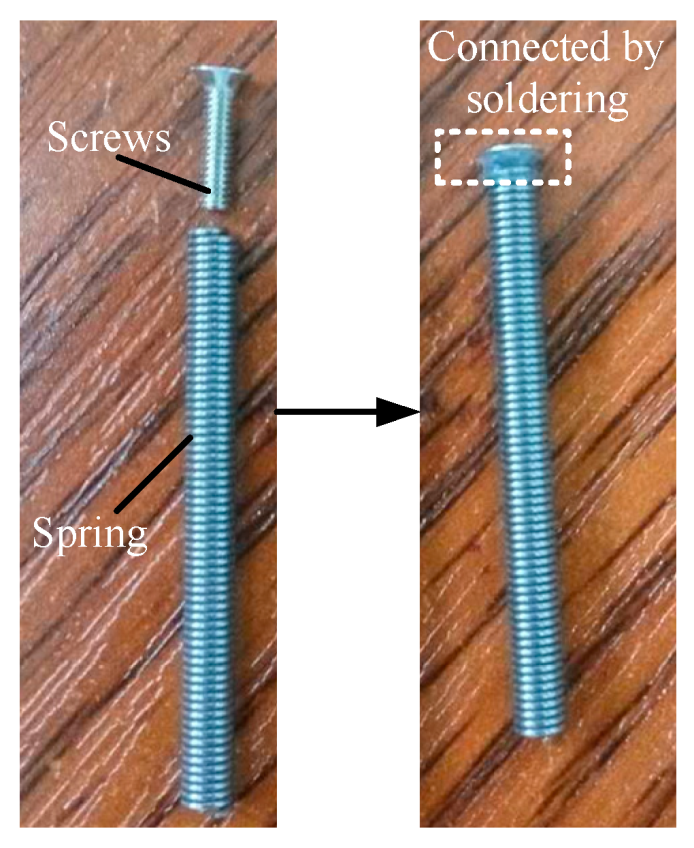
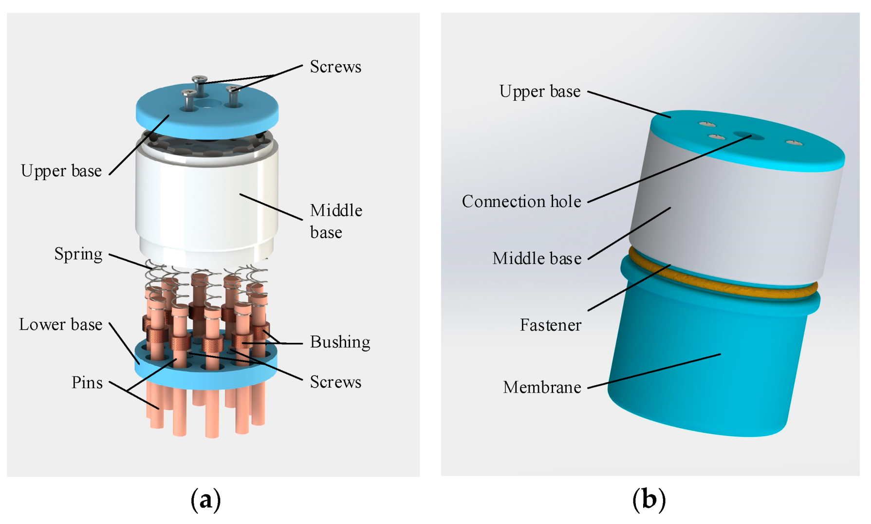
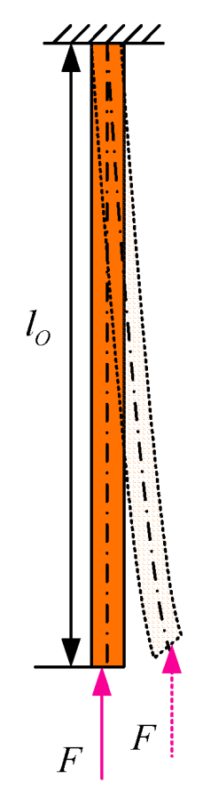
Use the bendable pin to take place of the rigid slide tube assembly of the CTSA hand. The bendable pin has rigidity in its axial direction and can withstand the axial force without obvious deformation. In addition, the bendable pin has flexibility in the directions perpendicular to its axis, which means the pin can be bent when subjected to a lateral load and can revert to the initial position after the lateral load is removed. By replacing the rigid sliding tube with a bendable pin, and replacing the swinging with bending, the mechanical structure is greatly simplified, and the assembly difficulty is reduced, making the possibility of mass production higher.
(2)
Wrap all pins with a membrane. On the one hand, the pins are isolated from the outside world to avoid damage to the sliding mechanism by impurities such as dust outside, and on the other hand, the contact area between the robot hand and the object is increased, improving the reliability of grasping.
(3)
The fluid drive is used instead of the tendon driving with pneumatic driving. Changing the driving mode avoids the use of the motor and gears, which can reduce the size of the device and greatly simplify the mechanism of the device.
Using the above ideas, a soft robot hand with the structure of pin array, CTSA-II hand, was designed. The expected design of CTSA-II hand is shown in Figure 5. The CTSA-II hand includes a base, a set of pin assemblies and a membrane. Each pin assembly includes a spring and a bendable pin. The base is provided with several holes, each of which is a chute for each pin assembly. The membrane wraps all pin assemblies to form a closed cavity for pneumatic driving. The negative pressure causes all of the pins to bend and gather toward the center of the CTSA-II hand.

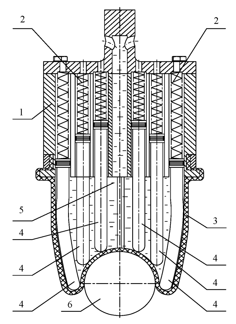
3.2. The Specific Structure of the Robot Hand

According to the design idea of Section 3.1, the detailed structural design of the CTSA-II hand was designed through multiple design improvements and prototype assembly experiments, as shown in Figure 6.
The CTSA-II hand mainly includes an upper base, a middle base, a lower base, N groups of pin assembly, membrane, and fasteners. Each pin assembly includes a spring, a pin, and a bushing. The upper base, the middle base, and the lower base are, respectively, provided with a connection hole, and the middle base and the lower base provided with N hole for N groups of pin assembly. The spring of each pin assembly is disposed in each hole of the middle base, the bushing of each pin assembly is disposed in each hole of the lower base, and the pin of each pin assembly is sleeved between the middle base and the lower base. The pins have a larger diameter at one end, so that it can slide in the base without falling out. The upper base, the middle base, and the lower base are screwed together. The membrane wraps all the pin assemblies and is fixed to the base by the fasteners. The entire device forms a cavity and is connected to the negative pressure source only through the connection holes.
The components of the robot hand are few and the structure is simple, which will become an important advantage in mass production and application.

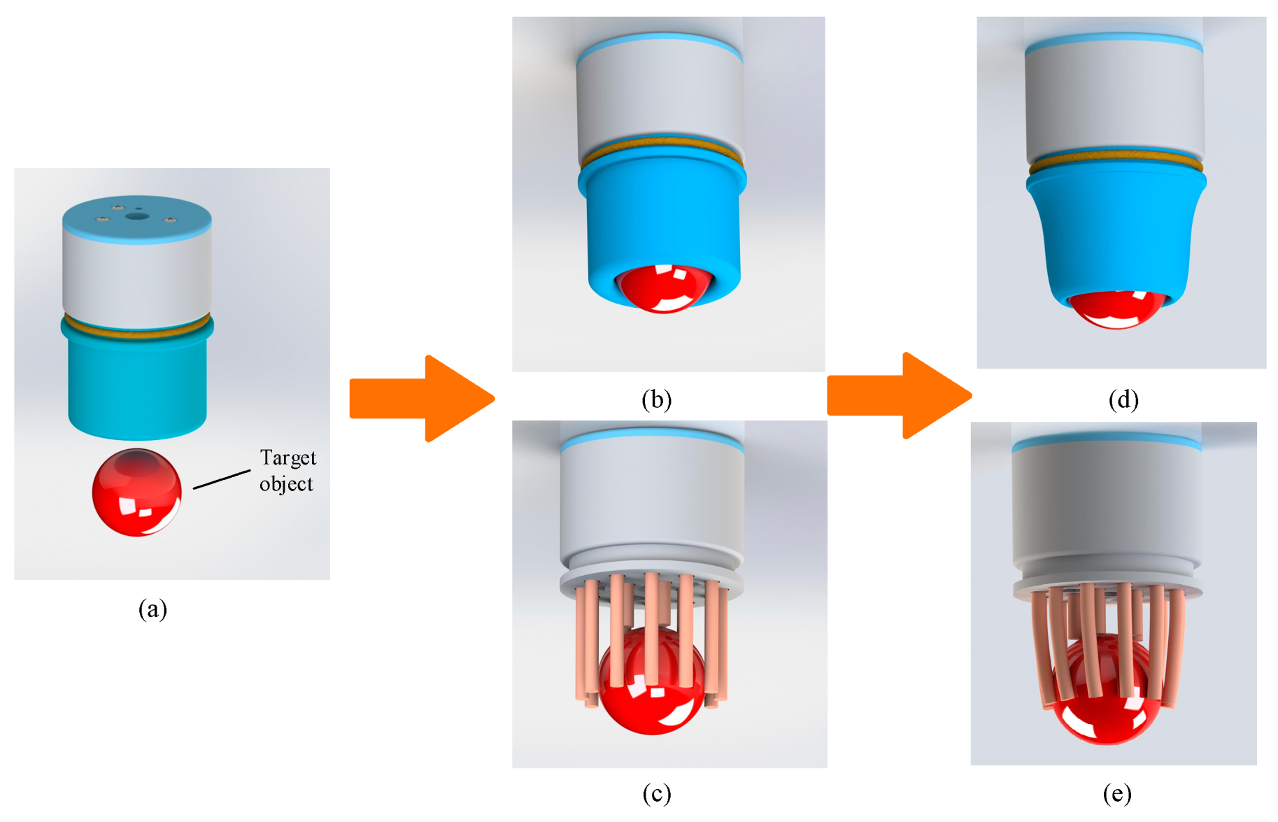
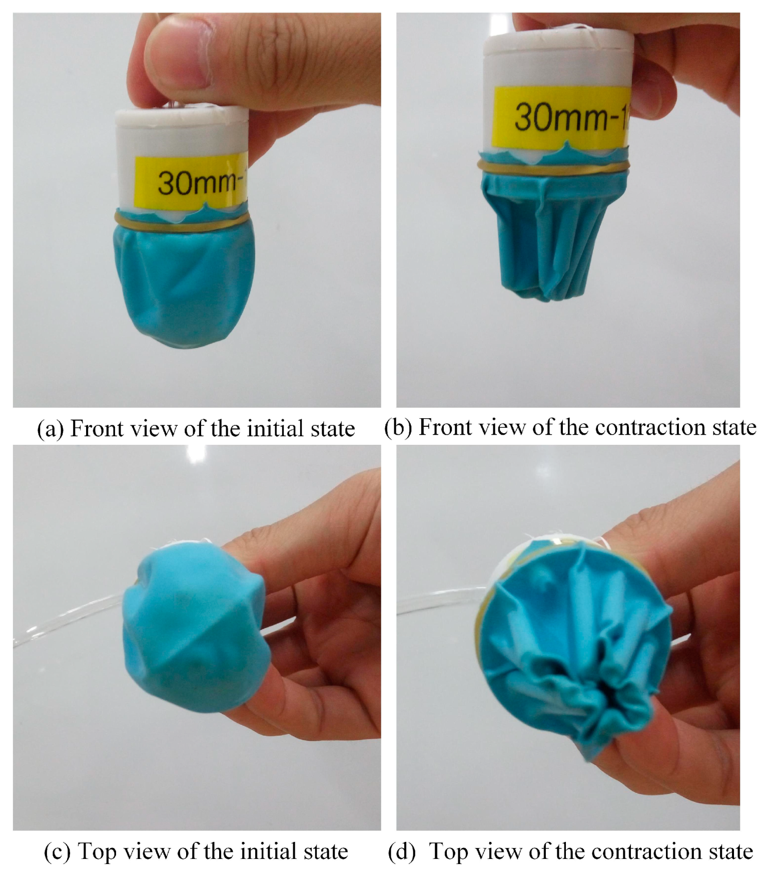
3.3. Grasping Principle

The CTSA-II hand was used to grasping an object. When grasping an object, it is mainly divided into two steps: a self-adaptive step and a grabbing step, as shown in Figure 7.
In the self-adaptive step, the CTSA-II hand approaches the object placed on the support surface. Depending on the shape of the object, different pins slide to varying degrees to adapt to the shape of the object from the vertical direction. Since the pin array is covered with the membrane, the membrane is attached to the surface of the object under the action of the pin array and the object, as shown in Figure 7b,c.
In the grasping step, the negative pressure source outside the CTSA-II hand starts working through the connection hole, so that the pressure of the internal cavity of the CTSA-II hand is smaller than the pressure of external atmospheric so that the membrane shrinks and the pin array is inwardly pressed. Since the pins are bendable, the pins will be deformed under the action of the film, as shown in Figure 7d,e, and then the membrane is driven to more closely wrap the object from the side, and the grasping force is generated. If a closed cavity is formed between the membrane and the object during this process, the cavity will generate negative pressure-assisted grip when the CTSA-II hand moves to enhance the reliability of grasping.
When the object needs to be released, the CTSA-II hand is stopped from connecting to the negative pressure and is connected its internal cavity to the atmosphere. Because of the existence of the springs, the pins will return to the initial position in the vertical direction. Since the pins have elasticity, the pins will return to the initial position in the lateral direction, thereby returning the membrane to the initial position and stopping the grasping force on the object.

4. Analyze

In this section, the main analysis is to research on the model of pin assembly. The discussion includes the gripping force provided by a bendable pin and the stability of a bendable pin. For the convenience of research, the simplified model of CTSA-II hand is shown in Figure 8, where the origin of the coordinate system is established at the center of the lower base. The parameters used in this section and the meanings and units of these parameters are shown in Table 1.

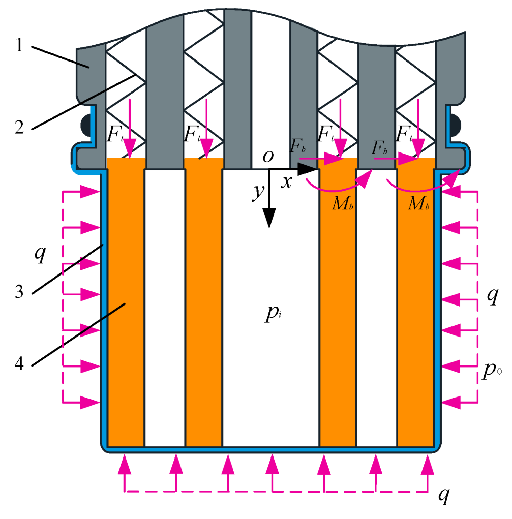
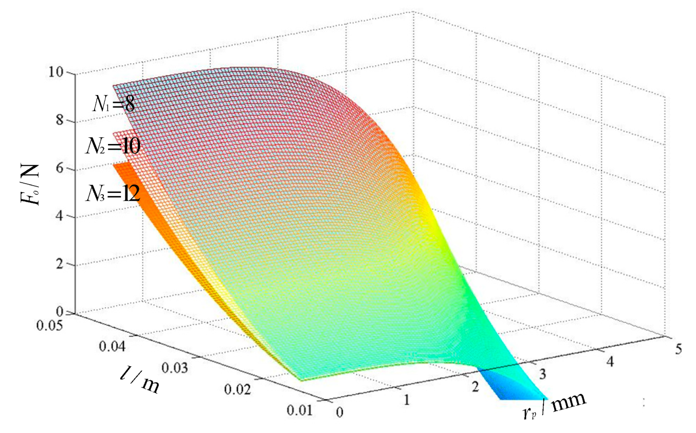
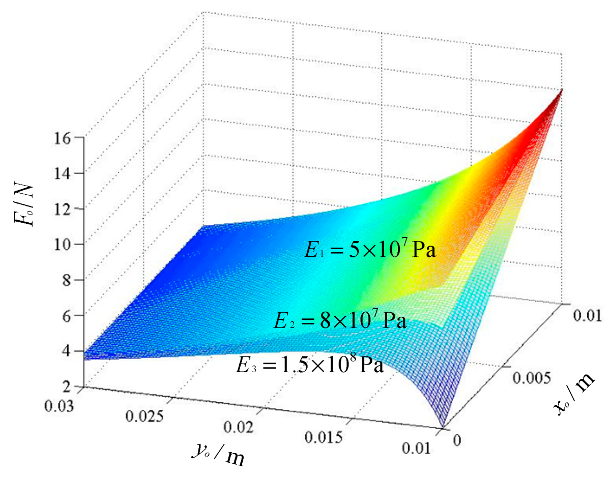
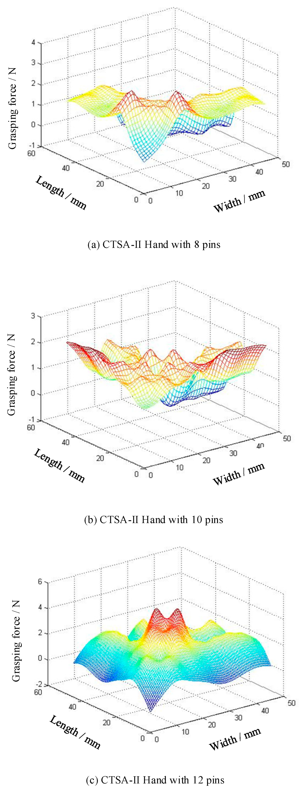
4.1. Analysis of the Grasping Force

This section mainly analyzes the grasping force that one pin can provide. For the convenience of research, assume that the CTSA-II hand is grabbing a sphere with a radius Ro placed at (xo, yo), ignoring the elasticity of the membrane. The force analysis can be simplified as shown in Figure 9. This section will mainly analyze how the characteristics of the sphere, the size of the pin, and the size of the base affect the grasping force of one pin.
The distribution force of a pin by membrane satisfies:
( p 0 p i ) · 2 π r l = N · q l
In the gripping process, the pin is equivalent to a cantilever beam of which one end is fixed at the base. Through static analysis, the force and moment that base acts on one pin follow:
F b = F o q l
M b + 0 l q y dy F o y 0 = 0
To calculate Fo, this paper uses the method of material mechanics. Divide the pin into two parts according to the contact point between the pin and the object, and the bending moments Mi(y)(i = 1, 2) of the two parts satisfy:
{ M 1 ( y ) + q y dy + M b = 0 ( 0 < y y 0 ) M 2 ( y ) + q y dy + M b F o y 0 = 0 ( y 0 y < l )
We solve Fo by the approximately differential equation of the deflection curve [27]:
d 2 ω i d y 2 = M i ( y ) E I ( i = 1 , 2 )
In this differential equation, the boundary conditions are:
ω i ( 0 ) = 0 , d ω 1 d y | y = 0 = 0 , ω 1 ( y 0 ) = ω 2 ( y 0 ) , d ω 1 d y | y = y 0 = d ω 2 d y | y = y 0
By jointly solving Equations (1)–(6), the deflection distribution is:
{ ω 1 ( y ) = q y 4 24 + 1 2 ( 1 2 q l 2 F o y 0 ) · y 2 E I ω 2 ( y ) = q y 4 24 + 1 4 q l 2 y 2 F o y 0 2 y + 1 2 F o y 0 3 E I
At the point where the pin is in contact with the object, the deflection is determined by:
ω 1 ( y 0 ) = r x o R o
So,
F o = 24 E I ( r x o R o ) + ( p 0 p i ) · 2 π r N ( 6 l 2 y 0 2 y 0 4 ) 12 y 0 3
Equation (9) shows almost all the factors that affect Fo, including the position and size of the target object, the elastic modulus, the size of the pin, the size of the base, etc. Equation (9) has important guiding significance for the design of the CTSA-II hand.
From Equation (9), Fo is linear with pi. If pi is smaller, Fo is larger. However, relatively speaking, the smaller the pi, the greater the power consumption required. Therefore, the pressure selected during the crawling process needs to be weighed. However, in order to ensure the gripping force, the internal pressure of the device should satisfy:
p i < p 0 12 E I N ( r x o R o ) ( 6 l 2 y 0 2 y 0 4 ) π r
For the parameters r, it can be seen from Equation (9) that the gripping force is linear with r, but there are many factors affecting the partial conductance of r, as shown in Equation (11):
F o r = ( p 0 p i ) π l 2 N y 0 2 E I y 0 3
It can be seen that it is not possible to determine whether it is positive or negative. For the parameter N, from the perspective of a single unit, it is an inverse relationship between Fo and N. However, as a whole, the increase of N will increase the number of pins that can provide the gripping force, which may bring better performance. The appropriate N is not determined through this discussion, and it may be better determined by experiments.
Suppose the pin has a circular cross-section with a radius of rp, so I = π r p 4 / 16 , and then the following equation can be obtained:
F o = 6 π r p 4 E I ( r x o R o ) + ( p 0 p i ) · 2 π r N ( 6 l 2 y 0 2 y 0 4 ) 12 y 0 3
According to Equation (12), the relationship between Fo and the radius, length, and quantity of pin can be shown in Figure 10. It can be seen from the curved surface in Figure 10 that the length of the pin has a great influence on Fo, and the radius of the pin has almost no influence on Fo. Therefore, under the premise of smallness, the longer pin is selected, and the better crawling performance will be performed. In addition, the number of pins has a minor effect on Fo. The smaller the number of pins, the greater the Fo. However, in some areas of Figure 10, Fo becomes a negative value, which indicates that under the conditions of the area, the pin cannot provide the gripping force, which should be avoided. There are many reasons for this, such as the fact that the pin is too thick, so that under certain pressure conditions, the pin does not produce sufficient bending to provide a grasping force.
In addition, in order to find out how the position of the target object (sphere) affects Fo, this paper plots the surface as shown in Figure 11. It can be seen from Figure 11: (1) For xo, no matter what value E takes, the larger xo, the larger Fo, but E will influence the degree of influence of xo on Fo. (2) For yo, when E takes different values, yo has a different influence on Fo. Therefore, in the actual design, it is very important to select an appropriate E value. In general, in order to reduce the influence of the position of the object on the gripping force, a suitable value of E should be taken. For example, E2 in Figure 11 is appropriate.

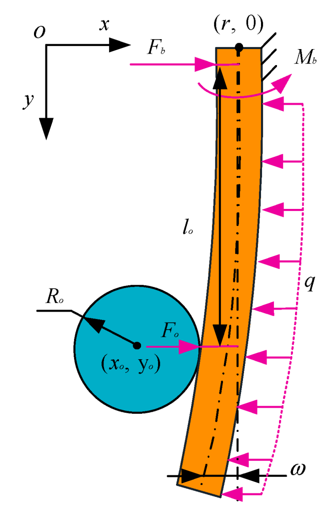
4.2. Stability Analysis of a Pin

Since the pin has two characteristics, on the one hand, it must have a certain rigidity: it needs to ensure that the pin can slide when it is thrust along the axial direction. On the other hand, it must have flexibility: it is necessary to ensure that the pin can bend when there is a lateral load on it. To have both of these characteristics, it is very likely that the pin will be unstable during sliding. As shown in Figure 12, this section mainly analyzes this issue theoretically.
The pin can be simplified as a model of an elongated compression rod with one end free and the other end fixed. The critical load [27] under this model is:
F c r = π 2 E I 4 l o 2
In this model,
F V = k Δ x
l o = l Δ x
If we want the pin not to be instable, we need:
F V < F c r , Δ x [ 0 , l )
Then,
4 k ( Δ x 3 2 l Δ x 2 + l 2 Δ x ) π 2 E I < 0
In order to keep the rod stable during the sliding process, it is necessary to always satisfy Equation (17) during the sliding process. Through mathematical derivation, the following conditions must be met to make Equation (17) constant:
16 k l 3 < 27 π 2 E I
Therefore, in order to avoid the occurrence of instability, a suitable combination of spring and pin should be selected so that the relevant parameters satisfy Equation (18).
For the parameter k, a smaller value of k should be chosen so that the resistance of the pin in the sliding of the base is small, which makes the pin slide easily, and makes Equation (18) easier to set up. However, k cannot be excessively small or it is hard to react the pins to their original position when CTSA-II does not work.
Synthesizing Equations (9) and (18), the selection of EI is a trade-off process. On the one hand, in order to obtain a larger grasping force, a smaller EI value should be taken. On the other hand, from Equation (18), in order to obtain more stable performance, a larger EI value should be taken. Therefore, this paper will use experiments to select a material having a suitable EI to make the pin.

5. The Prototype and the Experiments

5.1. The Development of the Prototype

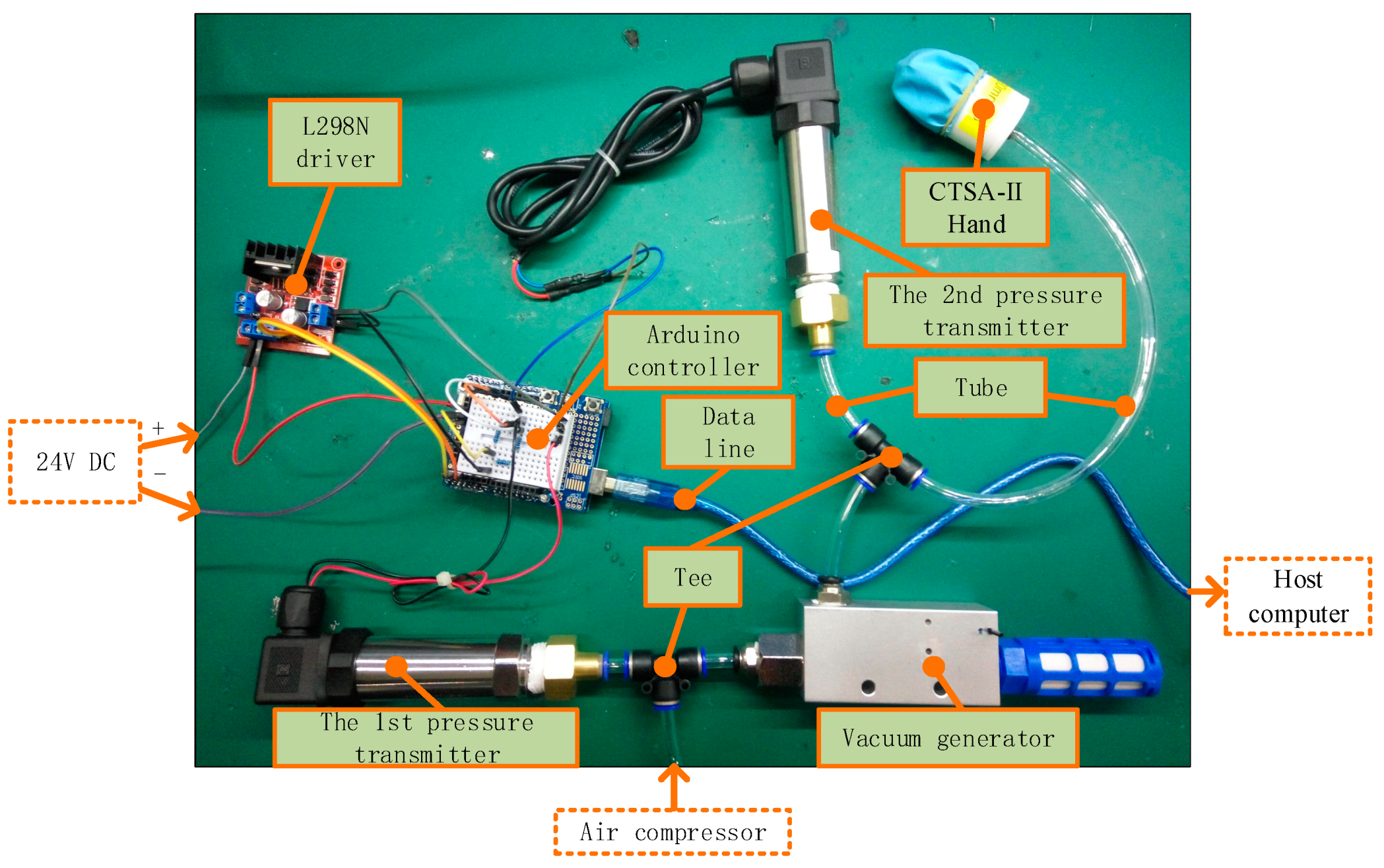
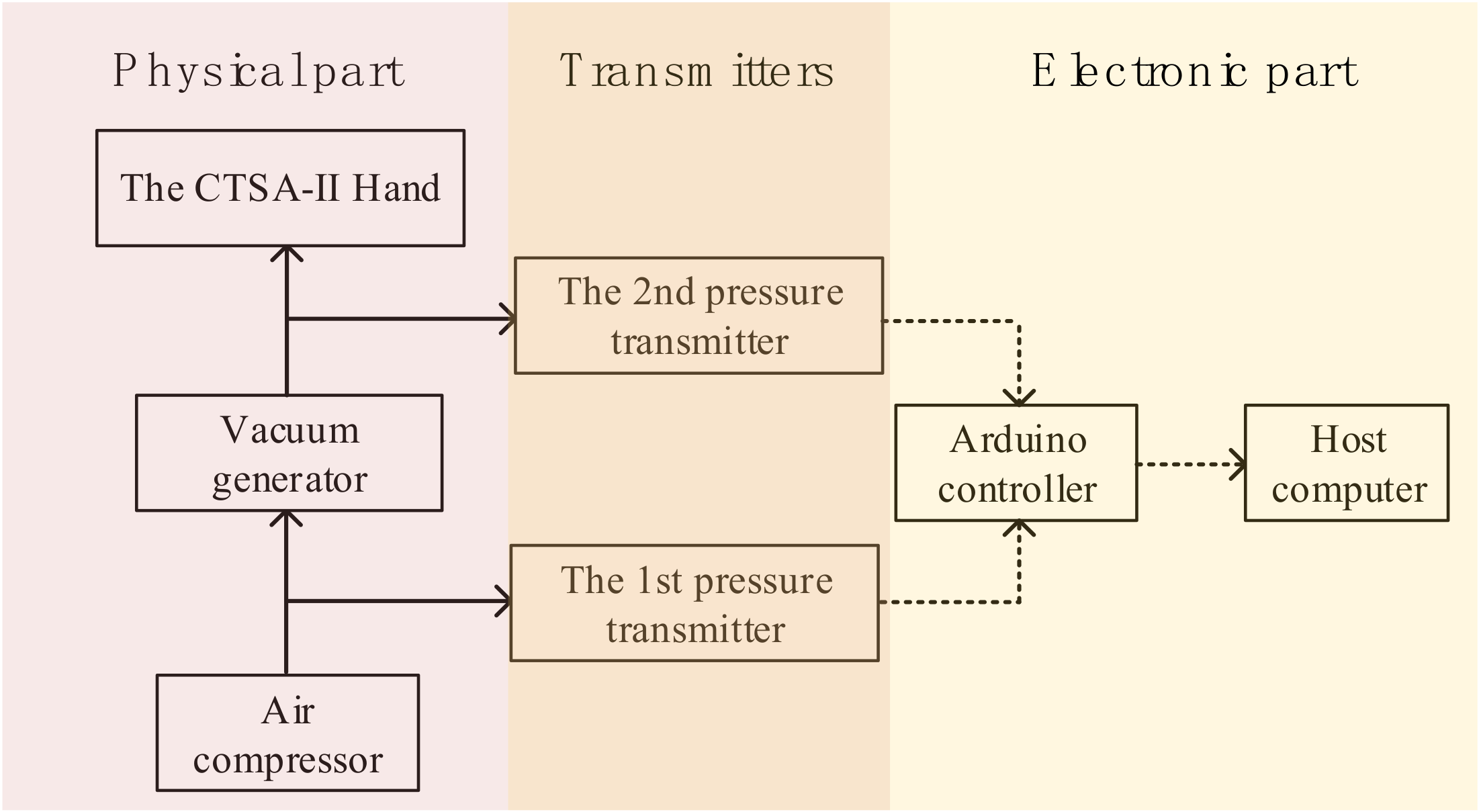
5.1.1. Component Selection

Through the derivation of theoretical analysis, the difficulty of assembly is weighed, and the size parameters of the prototype are shown in Table 2.
In the development process, through the comparison of various materials, a combination of a tension spring with a large modulus of elasticity and a short screw is selected to make the pins, as shown in Figure 13. Since the value EI of the material is difficult to measure, the material of the tension spring is selected from various forms of materials by experiments. Through some experiments, the parameters of the spring are determined: the outer diameter is 3 mm, the wire diameter is 0.5 mm, the length is 30 mm, and the material is spring steel.
From the previous analysis, it is known that the size of the membrane affects the gripping force in a variable manner. Therefore, the material selection of the membrane is considered the basic properties. The membrane needs to have a certain elasticity, so it is good to be processed by a balloon. If the membrane size is small, it will pre-stress the pin when CTSA-II hand does not work, which is unnecessary; when the membrane size is large, it will bring excessive energy consumption. Therefore, considering the comprehensive consideration, a 7-inch-matt-thick balloon is used to manufacture the membrane of the CTSA-II hand.
Therefore, the parameters of the components of the CTSA-II hand are shown in Table 3, and the base of CTSA-II hand is manufactured by 3D printing.

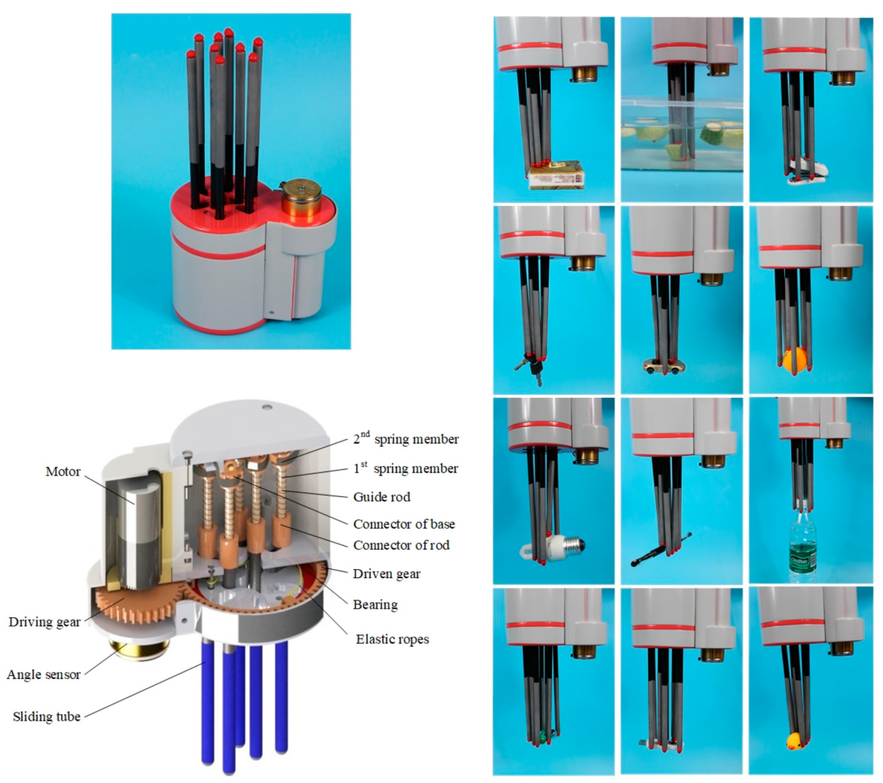
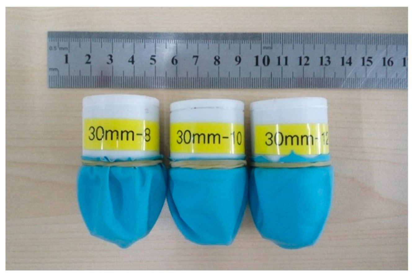
5.1.2. The Prototype of CTSA-II Hand

According to the selected components in Section 5.1.1, the three types of CTSA-II prototypes are assembled as shown in Figure 14. In the assembly process, the assembly difficulty is much less than that of the CTSA hand, which provides a prospect for wide application of CTSA-II hand.
The three prototypes of CTSA-II all have a lightweight, and the masses of the three prototypes are shown in Table 4. As can be seen from Table 4, the masses of the three prototypes are all about 30 g. The number of pin assemblies has a certain degree of influence on the mass, but this degree of difference does not affect the operational performance of the CTSA-II hand.
The comparison of contraction state and the initial state of the CTSA-II hand is as shown in Figure 15 and Movie S1 (Supplementary Materials). As can be seen from Figure 15, the contracted state is significantly deformed compared to the initial state, and the bottom of the pin array is substantially gathered, so the CTSA-II hand has a gripping function. Next, the CTSA-II hand will be subjected to the experiment of grab function verification and grab performance analysis.

5.2. The Experiments with the Verification of the Crawl Function

In order to verify the adaptive gripping performance of the CTSA-II hand, the CTSA-II hand is used to grasp various objects commonly found in daily life, as shown in Movie S2 and Movie S3. The type and quality of the grasped object and the grasping posture of the CTSA-II hand are shown in Figure 16.
In the verification experiments, the output pressure of the air compressor is maintained at three units of atmospheric pressure (relative), and the CTSA-II hand prototype with a pin assembly number of 12 was selected. As can be seen from Figure 16, the CTSA-II hand has a high degree of fit to the object when grasping the object, and can grasp various objects effectively.
Therefore, preliminary conclusions can be drawn through the verification experiments:
(1)
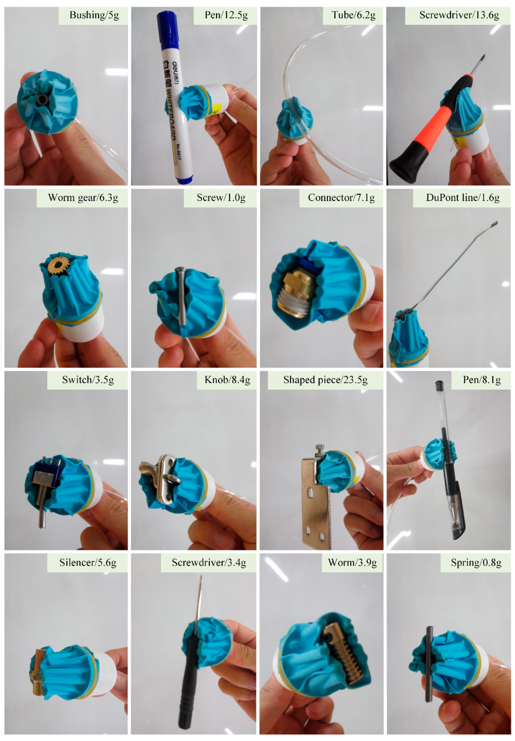
The CTSA-II hand has a high degree of self-adaptation, and can effectively capture objects of different sizes, shapes, materials, and qualities;
(2)
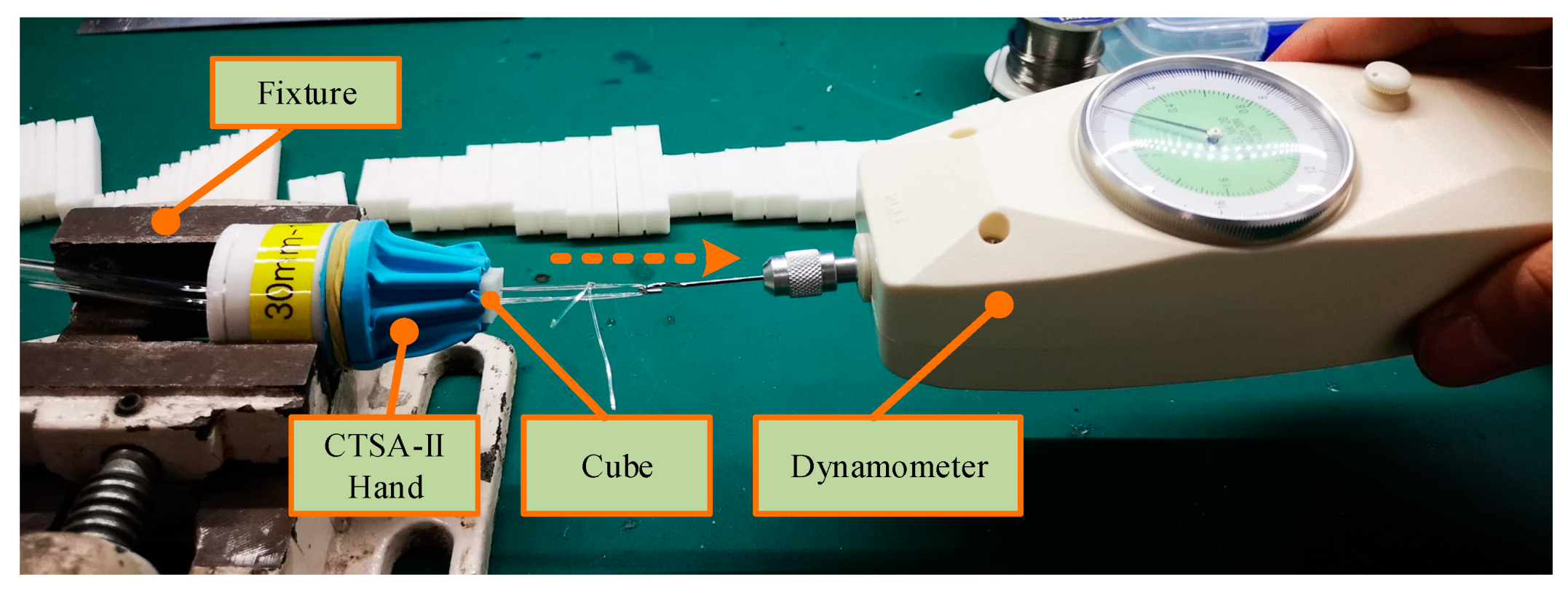
The CTSA-II hand has a high success rate of grabbing and reliable gripping.
Authors should discuss the results and how they can be interpreted in perspective of previous studies and of the working hypotheses. The findings and their implications should be discussed in the possible broadest context. Future research directions may also be highlighted.

5.3. Experiments with the Exploration of Grab Performance

In order to thoroughly study the performance of CTSA-II hand, this section will comprehensively study how various factors effects on the performance of the grasping of CTSA-II hand. This section will explore the following factors: the internal pressure of CTSA-II hand, the position of the object, and the size of the target object.

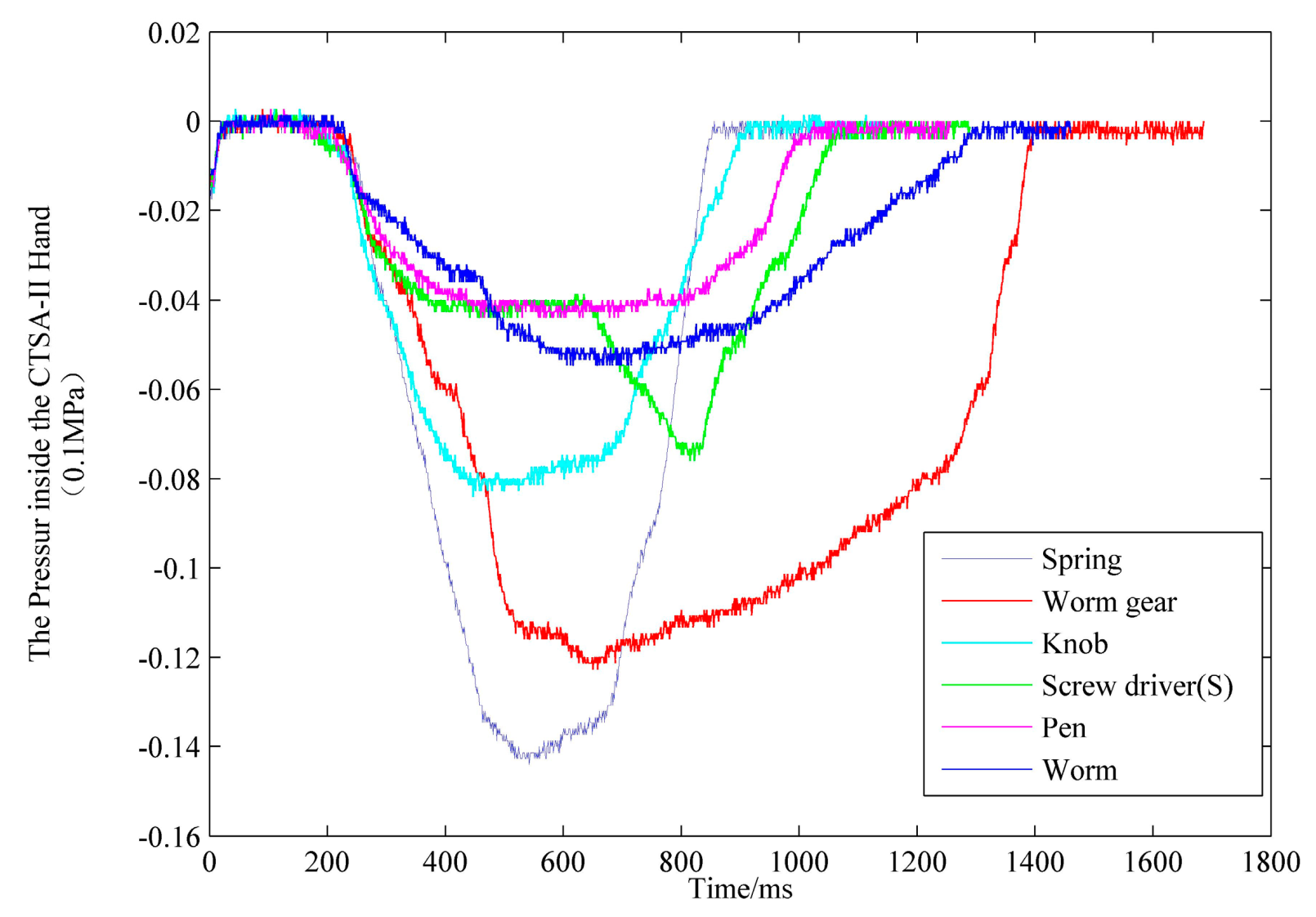
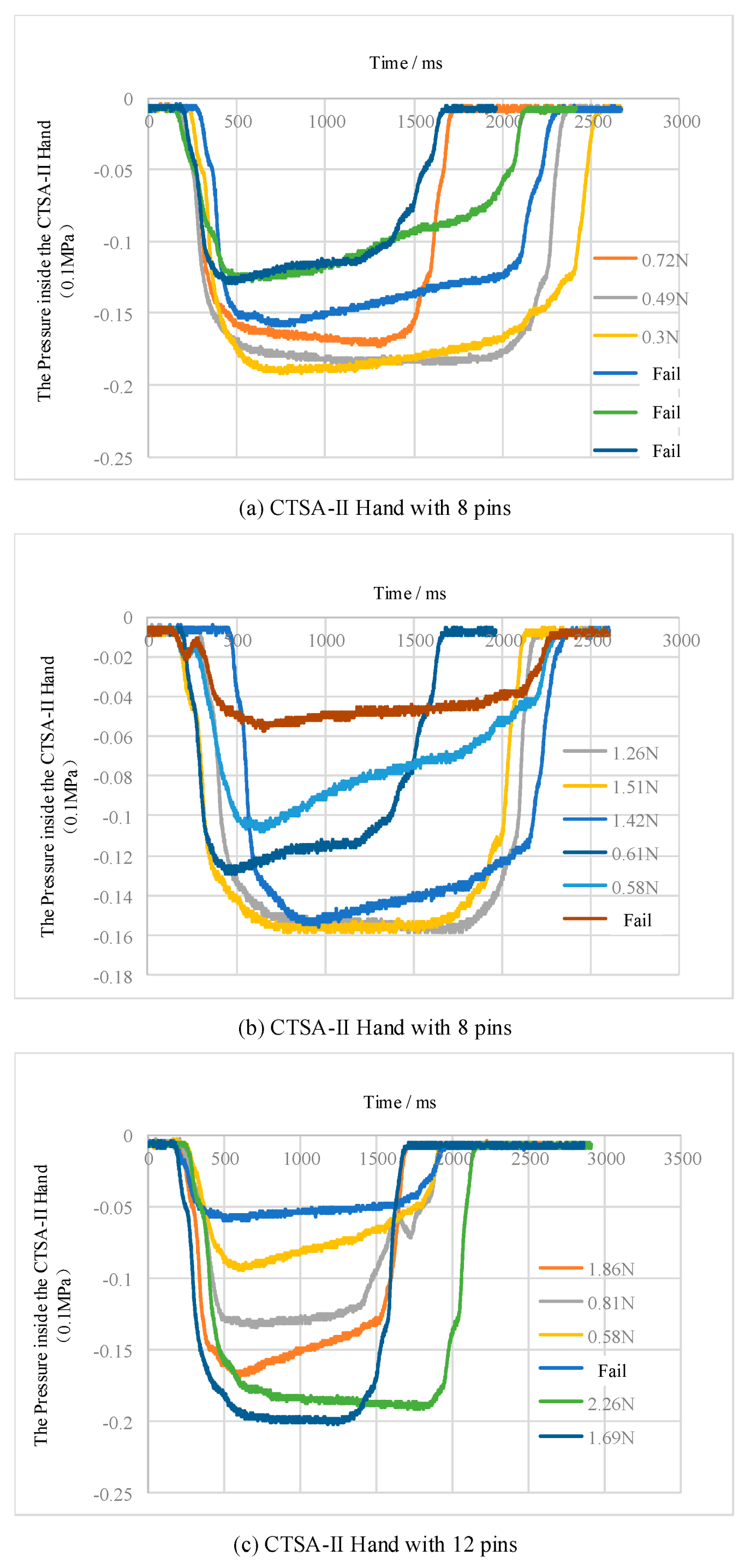
5.3.1. The Internal Pressure of CTSA-II Hand

To explore the relationship between pressure and grasping force, two different ranges of pressure transmitters were used to measure the pressure, the static parameter characteristics of the two pressure transmitters are shown in Table 5. The first pressure transmitter range (relative pressure) was 0–1 MPa, which was used to measure the pressure of the air compressor output. The range (relative pressure) of the second pressure transmitter was −0.1 MPa–0, which was used to measure the pressure inside the CTAS-II hand. The Arduino controller was used to receive the data from two sensors and transfer the data to the host computer. The experimental platform was set up as shown in Figure 17, and its structural relationship is shown in Figure 18.
The experimental platform is mainly divided into a physical part and an electronic part, and these two parts are connected by two pressure transmitters. The physical part includes an air compressor, air pipes, tee, and CTSA-II hand; the electronic part includes 24V DC-regulated power, L298N, Arduino controller, data lines, and a host computer. The first pressure transmitter detects the positive pressure of the output of the air compressor, the second pressure transmitter detects the negative pressure of the CTSA-II hand, and the detected pressure signal is converted into an electrical signal to be transferred to the host computer to process.
First, the characteristics of the vacuum generator, that is, the relationship between the input air pressure and the output air pressure, were obtained, and the result are shown in Figure 19. It can be seen from Figure 19 that the output air pressure is substantially linearly related to the input air pressure, and the higher the input air pressure, the lower the output pressure.
After the input–output pressure of gas relationship is basically determined, the basic concept of the pressure of CTSA-II hand can be obtained by the indication of the air compressor table. Moreover, the basic driving by the combination of the air compressor and the vacuum generator can be controlled by the table of an air compressor. However, the way to drive the CTSA-II hand is not only the combination of the air compressor and the vacuum generator, but also the vacuum pump and other methods. Therefore, in order to obtain the performance of the CTSA-II hand prototype itself, this paper only explores the relationship between the internal pressure of CTSA-II hand and the grasping force.
Firstly, we explored the change of internal pressure during the grasping process. The CTSA-II hand with 10 pins was used to grasping several objects shown in Figure 16. The air pressure change during the grasping process is as shown in Figure 20.
It can be seen from the curve that during the grab-to-release process: the pressure inside the CTSA-II hand is reduced to achieve the grab, and the pressure in the CTSA-II hand is increased to achieve the release. It should be noted that the slope and peak value of the curve in the grab curve are mainly related to the speed and degree of the switch valve, and have no reference value.
To qualitatively investigate the effect of internal pressure on the grasping force, three CTSA-II hand prototypes were used to grab cubes with a size of 10 mm (length) × 10 mm (width) × 10 mm (height) under different pressure conditions and measure the grasping force.
The way to measure the grasping force is as shown in Figure 21: grasp the object with CTSA-II hand firstly, and then use the dynamometer to pull the object slowly out of the CTSA-II hand; the peak of the dynamometer during the pulling process was used as the grasping force. In order to ensure the rationality, the measurement was performed 3 times and then the average of the 3 times was taken.
For the grasping force measurement in this way, the most ideal method of applying force is as follows: increase the value of the dynamometer slowly enough, so that the pulling force that the cube is subjected to gradually increases from 0 until the cube moves, then slowly pull the cube out of the CTSA and the peak value in the process is the true grasping force. When using manual pull, a certain error will be formed. However, since the experimenters in this paper were all conducted by the same person, the experimental conditions were equivalent, and the average value was measured by three measurements. Therefore, most of the errors caused by the previous force measurement method on the exploration of the overall performance can be ignored.
Finally, the relationships between the pressure in the CTSA-II hand and the grasping force during the grasping process of the three types of prototypes are shown in Figure 22. It can be concluded from Figure 22 that: (1) The smaller the pressure in the CTSA-II hand, the larger the grasping force, which is in line with the theoretical derivation in Section 4. (2) When the pressure in the CTSA-II hand is not small enough, it is easy to cause grab failure. (3) When the pressure (relative) is −0.15 units of atmospheres, all 3 prototypes can achieve stable crawling. (4) Comparing the three graphs in Figure 22, the CTSA-II hand with 8 pins fails when the pressure (relative) is −0.12 units of atmospheres or so, while the CTSA-II hand with 10 pins and 12 pins fail when the pressure (relative) is about −0.05 atmospheres, so the grasping performances of the 10 and 12 CTSA-II grips are better.

5.3.2. The Size of the Target Object

This section explores the effect of the cross-sectional dimensions on the gripping force.
In order to explore the influence of the cross-sectional dimensions of the object on the grasping force, the method of exploring was to: use a 3D printer to print a number of cubes each having a height of 10 mm but different lengths (between 5 mm and 50 mm) and different widths (between 5 mm and 50 mm). Each of the cubes was grabbed and the grasping force was measured using three types of the CTSA-II hand. The method to measure the grasping force is the same as the method of measuring the grasping force in Section 5.3.1. The dial of the air compressor was used to ensure that the relative positive pressure of the air compressor input is 3 units of atmospheric pressure.
After obtaining the grasping data of three kinds of CTSA-II hands on different sizes of objects, we used mathematical tools to fit the data to obtain the results shown in Figure 23, and the negative values in Figure 23 indicate that the crawl has failed.
As can be seen from Figure 23, all of the three types of the CTSA-II can provide effective grasping force, and the average grasping force is about 2 N, that is, it can grab about 200 g of objects. As can be seen from the mass of the conventional object shown in Figure 16, 200 g is already a considerable mass, indicating that the grasping force of 2 N is sufficient for a small-sized CTSA-II hand.
By comparing the three graphs in Figure 23, it can be found that when the number of pins is small, the grasping surface has a large degree of jitter, and when the number of pins is 12, the degree of surface jitter is relatively small. When the number of pins is large, the grasping force of the CTSA-II hand is less affected by the cross-sectional size of the object, and the grasping is more stable; meanwhile, the overall grasping force is large when the number of pins is 12. Therefore, in order to reduce the influence of the cross-sectional dimension of the object on the grasping stability, the CTSA-II hand with 12 pins has better grasping performance.

5.3.3. The Position of the Object

The degree of the effect of the position of the target object on the grasping performance is one of the important criteria for judging the performance of a gripper. This section will explore the influence of the position of the target object on the grasping performance. The method is: in the circle with a diameter of 30 mm under the vertical projection of the CTSA-II hand, the distance from the center of the object to the center of the circle was recorded as the offset distance; CTSA-II hands with different pins were used to grab a 5 mm × 5 mm × 10 mm cube with different offset distances. Each set of tests was conducted 10 times and the success rate of each set was recorded.
The experimental results obtained are shown in Table 6. From Table 6, it can be concluded that the CTSA-II can effectively grasp the object within the deviation range of 5 mm without any mistakes. However, when the offset distance is too large, the CTSA-II hand grab is prone to failure. In the three types of CTSA-II hands, the prototype with 8 pins is less affected by the offset distance.

6. Conclusions

This paper proposed, designed, developed and studied a soft robot hand with pin-array structure, which has the following conclusions:
(1)
The grasping mode of CTSA was studied: the pin array slides up and down to realize the self-adaption to the shape and size of the target object, and then all the pins are gathered to the center to grasp an object.
(2)
According to the CTSA mode and the shortage of CTSA hand, a soft robot hand with pin-array structure (CTSA-II hand) was designed and a theoretical model was established. The CTSA-II hand has the characteristics of simple structure and easy assembly. Theoretical modeling analysis shows that CTSA-II can provide sufficient grasping force for conventional small objects, and can be stable when working. The factors affecting the grasping force CTSA-II hand were studied theoretically.
(3)
A series of prototypes of CTSA-II hand with different numbers of pins were developed and a large number of gripping experiments were carried out. The CTSA-II hand prototype has the advantages of small size, light weight, and easy assembly. Through a large number of experiments, the CTSA-II has a high degree of fit to the object when grasping the object, sufficient grasping force, high grip reliability, and good fault tolerance rate of the object position information.
In the follow-up work, the main problems to be solved are: (1) implementing automated crawling and studying a reasonable set of crawling strategies; (2) optimizing the design of the CTSA-II hand and forming a normalized design system to optimize the CTSA-II hand design with optimal parameters for different gripping situations.

Supplementary Materials

The following are available online at https://www.mdpi.com/2076-3417/9/5/1011/s1, MovieS1: Driving experiment without grabbing an object; MovieS2: Grasping experiments of conventional objects; MovieS3: Working with the robotic arm.

Author Contributions

The individual contributions of authors: conceptualization, H.F. and W.Z.; methodology, H.F.; validation, H.F.; formal analysis, H.F.; investigation, W.Z.; resources, W.Z.; data curation, H.F.; writing of original draft preparation, H.F.; writing of review and editing, H.F. and W.Z.; visualization, H.F.; project administration, W.Z.; funding acquisition, W.Z.

Funding

This research was supported by the National Natural Science Foundation of China (No. 51575302), Beijing Natural Science Foundation (No. J170005) and National Key R&D Program of China (No. 2017YFE0113200).

Conflicts of Interest

The authors declare no conflicts of interest.

References

  1. MPG Hand. Available online: https://schunk.com/cn_zh/zhua-qu-xi-tong/series/mpg/ (accessed on 17 February 2019).
  2. MPZ Hand. Available online: https://schunk.com/cn_zh/zhua-qu-xi-tong/series/mpz/ (accessed on 17 February 2019).
  3. Salisbury, J.K.; Craig, J.J. Articulated hands: Force control and kinematic issues. Int. J. Robot. Res. 1986, 1, 4–17. [Google Scholar] [CrossRef]
  4. Jacobsen, S.; Iversen, E.; Knutti, D.; Johnson, R.; Biggers, K. Design of the Utah/MIT Dextrous Hand. IEEE Int. Conf. Robot. Autom. 1986, 3, 1520–1532. [Google Scholar]
  5. Kawasaki, H. Mechanism Design of Anthropomorphic Robot: Gifu Hand I. J. Robot. Mechatron. 1999, 11, 269–273. [Google Scholar] [CrossRef]
  6. Kawasaki, H.; Komatsu, T.; Uchiyama, K. Dexterous anthropomorphic robot hand with distributed tactile sensor: Gifu hand II. IEEE/ASME Trans. Mechatron. 2002, 7, 296–303. [Google Scholar] [CrossRef]
  7. Mouri, T.; Kawasaki, H.; Ito, S.; Shimomura, H. Anthropomorphic Robot Hand: Gifu Hand III. In Proceedings of the International Conference on Control, Automation and Systems, Xiamen, China, 16–19 June 2002; pp. 1288–1293. [Google Scholar]
  8. Shadow Hand. Available online: https://www.shadowrobot.com/products/dexterous-hand/ (accessed on 17 February 2019).
  9. Dollar, A.M.; Howe, R.D. The SDM Hand: A highly adaptive compliant grasper for unstructured environments. Springer Tracts Adv. Robot. 2009, 54, 3–11. [Google Scholar]
  10. Gaiser, I.; Schulz, S.; Kargov, A.; Klosek, H.; Bierbaum, A.; Pylatiuk, C.; Oberle, R.; Werner, T.; Asfo, T. A new anthropomorphic robotic hand. In Proceedings of the Humanoids 2008–8th IEEE-RAS International. Conference on Humanoid Robots, Daejeon, Korea, 1–3 December 2008; pp. 418–422. [Google Scholar]
  11. Xu, K.; Liu, H.; Du, Y.; Zhu, X. Design of an underactuated anthropomorphic hand with mechanically implemented postural synergies. Adv. Robot. 2014, 28, 1459–1474. [Google Scholar] [CrossRef]
  12. Zhang, W.; Che, D.; Liu, H.; Ma, X.; Chen, Q.; Du, D.; Sun, Z. Super under-actuated multi-fingered mechanical hand with modular self-adaptive gear-rack mechanism. Ind. Robot Int. J. 2009, 36, 255–262. [Google Scholar] [CrossRef]
  13. Liang, D.; Song, J.; Zhang, W.; Sun, Z.; Chen, Q. PASA Hand: A novel parallel and self-adaptive underactuated hand with gear-link mechanisms. In International Conference on Intelligent Robotics and Applications; Springer: Berlin, Germany, 2016; pp. 134–146. [Google Scholar]
  14. Deimel, R.; Brock, O. A Novel Type of Compliant and Underactuated Robotic Hand for Dexterous Grasping; Sage Publications, Inc.: Saunders Oaks, CA, USA, 2016. [Google Scholar]
  15. Wei, Y.; Zhang, W. OS hand: Octopus-inspired self-adaptive underactuated hand with fluid-driven tentacles and force-changeable artificial muscles. In Proceedings of the 2017 IEEE International Conference on Robotics and Biomimetics (ROBIO), Macau, China, 5–8 December 2017; pp. 7–12. [Google Scholar]
  16. Miron, G.; Bédard, B.; Plante, J.S. Sleeved Bending Actuators for Soft Grippers: A Durable Solution for High Force-to-Weight Applications. Actuators 2018, 7, 40. [Google Scholar] [CrossRef]
  17. Viacheslav, S.; Seiji, E.; Pavel, G.; Vladimisky, D. Strategies to Control Performance of 3D-Printed, Cable-Driven Soft Polymer Actuators: From Simple Architectures to Gripper Prototype. Polymers 2018, 10, 846. [Google Scholar]
  18. Amend, J.R.; Brown, E.; Rodenberg, N.; Jaeger, H.M.; Lipson, H. A positive pressure universal gripper based on the jamming of granular material. IEEE Trans. Robot. 2012, 28, 341–350. [Google Scholar] [CrossRef]
  19. Nishida, T.; Okatani, Y.; Tadakuma, K. Development of universal robot gripper using mrα fluid. Int. J. Humanoid Robot. 2014, 13, 1650017. [Google Scholar] [CrossRef]
  20. Zhu, T.; Yang, H.; Zhang, W. A spherical self-adaptive gripper with shrinking of an elastic membrane. In Proceedings of the 2016 International Conference on Advanced Robotics and Mechatronics (ICARM), Macau, China, 18–20 August 2016; pp. 512–517. [Google Scholar]
  21. FlexShapeGripper. Available online: https://www.festo.com/group/zh/cms/10217.htm (accessed on 17 February 2019).
  22. Scott, P.B. The ‘Omnigripper’: A form of robot universal gripper. Robotica 1985, 3, 153–158. [Google Scholar] [CrossRef]
  23. Petterson, A.; Ohlsson, T.; Caldwell, D.G.; Davis, S.T. A bernoulli principle gripper for handling of planar and 3D (food) products. Ind. Robot Int. J. 2010, 37, 518–526. [Google Scholar] [CrossRef]
  24. Wang, S.; Jiang, H.; Cutkosky, M.R. Design and modeling of linearly-constrained compliant spines for human-scale locomotion on rocky surfaces. Int. J. Robot. Res. 2017, 36, 989–999. [Google Scholar] [CrossRef]
  25. Hauser, K.; Wang, S.; Cutkosky, M.R. Efficient equilibrium testing under adhesion and anisotropy using empirical contact force models. IEEE Trans. Robot. 2018, 99, 1–13. [Google Scholar] [CrossRef]
  26. Fu, H.; Yang, H.; Song, W.; Zhang, W. A novel cluster-tube self-adaptive robot hand. Robot. Biomim. 2017, 4, 25. [Google Scholar] [CrossRef] [PubMed]
  27. Gere, J.M.; Timoshenko, S.P. Mechanics of Materials; China Machine Press: Beijing, China, 2003. [Google Scholar]
Figure 1. The Omnigripper.
Applsci 09 01011 g001
Figure 2. The objects that omnigripper can or cannot crawl.
Applsci 09 01011 g002
Figure 3. The cluster tube self-adaptive (CTSA) grasping mode.
Applsci 09 01011 g003
Figure 4. The CTSA hand.
Applsci 09 01011 g004
Figure 5. The expected improved design of CTSA hand, including components: 1, base; 2, spring; 3, balloon membrane; 4, pins; 5, gas or fluid; 6, object.
Applsci 09 01011 g005
Figure 6. The design of the CTSA-II hand: (a) the explosion view, (b) the overall appearance.
Applsci 09 01011 g006
Figure 7. Grasping process of the robot hand: (a) before grasping, (b) self-adaptive step, (c) self-adaptive step hiding membrane, (d) gripping step, and (e) gripping step hiding membrane.
Applsci 09 01011 g007
Figure 8. The overall force situation: 1, base: 2, spring; 3, balloon membrane; 4, bendable sliding pins.
Applsci 09 01011 g008
Figure 9. Force analysis of single pin.
Applsci 09 01011 g009
Figure 10. Influences of rp, l, and N on Fo (r = 0.02 m, Ro = 0.015 m, xo = 0, yo = 0.03 m, E = 5 × 10⁷ Pa, po = 1.01 × 10⁵ Pa, and pi = 0.8 po).
Applsci 09 01011 g010
Figure 11. Influences of xo, yo, and E on Fo (r = 0.02 m, Ro = 0.01 m, l = 0.03 m, rp = 0.003 m, N = 12, po = 1.01 × 10⁵ Pa, and pi = 0.8 po).
Applsci 09 01011 g011
Figure 12. The instability of pin.
Applsci 09 01011 g012
Figure 13. The composition of the pin.
Applsci 09 01011 g013
Figure 14. Three CTSA-II hands with different numbers of pin assemblies.
Applsci 09 01011 g014
Figure 15. The comparison of contraction state and initial state.
Applsci 09 01011 g015
Figure 16. The experiments with the verification of the crawl function.
Applsci 09 01011 g016
Figure 17. The experimental platform of exploring pressure.
Applsci 09 01011 g017
Figure 18. The experimental structure of exploring pressure.
Applsci 09 01011 g018
Figure 19. The characteristics of the vacuum generator used in the system of CTSA-II hand.
Applsci 09 01011 g019
Figure 20. The change of internal pressure when the CTSA-II hand grasps objects.
Applsci 09 01011 g020
Figure 21. The experiment of measuring the grasping force.
Applsci 09 01011 g021
Figure 22. The relationships between the internal pressure and the grasping force.
Applsci 09 01011 g022
Figure 23. The relationships between the cross-sectional dimensions of objects and the grasping force.
Applsci 09 01011 g023
Table 1. The parameters used in the model of CTSA-II hand.
SymbolMeaningMeasure
E The elastic modulus of the pin Pa
F b The force of base acting on the pin N
F c r The critical force that causes the pin to lose its stability N
F o The force of a pin acting on the object N
F t The force of the spring on the pin N
F v The force acting on the rod from the vertical direction N
I The moment of inertia of the pin m 4
k The stiffness factor of the spring N / m
l The length of a pin m
l 0 The length of the pin protruding from the base m
M b The moment of base acting on the pin N · m
N The number of pins/
p i The pressure inside the CTSA-II hand Pa
p 0 The pressure outside the CTSA-II hand Pa
q The distribution force of a pin by membrane N / m
r The radius of the membrane that wraps all the pins m
r p The radius of the pin m
R o The radius of the target object m
x The deformation of the spring m
x o The abscissa of the target object m
x o The ordinate of the target object m
ω The deflection of a pin m
Table 2. The size parameters of the prototype.
Length of PinDiameter of PinDiameter of MembraneDiameter of Base
30 mm3 mm25 mm30 mm
Table 3. The parameters of the components of CTSA-II hand.
ComponentsBushingScrewsSpringSpring in pin
Model specification3 × 5 × 3, copper M2 × 120.3 × 4 × 300.5 × 3 × 30
Quantity8/10/1268/10/128/10/12
ComponentsScrew in pinmembraneAir compressorVacuum generator
Model specificationM2 × 67-inch balloonWB5500-1A25CV-20
Quantity8/10/12111
Table 4. The masses of 3 prototypes of CTSA-II hand.
Number of pins81012
Mass28.522 g32.138 g34.496 g
Table 5. The static parameter characteristics of the two pressure transmitters.
Full scalePrecisionStabilityTemperature Drift
The 1st sensor0–1 MPa0.2% FS0.1% FS/year0.01% FS/℃
The 2nd sensor−0.1 MPa~0
Table 6. The effect of the offset distance of the object on the grasping performance.
Offset Distance0 mm2.5 mm5 mm7.5 mm10 mm12.5 mm15 mm
Number of Pins
8100%100%100%100%60%30%10%
10100%100%100%90%70%30%20%
12100%100%100%90%50%20%0

