Article

Development of a Hybrid Electric Motorcycle that Accords Energy Efficiency and Controllability via an Inverse Differential Gear and Power Mode Switching Control

1
Center for Condensed Matter Sciences, National Taiwan University, Taipei 10617, Taiwan
2
Center of Atomic Initiative for New Materials, National Taiwan University, Taipei 10617, Taiwan
3
Department of Vehicle Engineering, National Taipei University of Technology, Taipei 10608, Taiwan
4
Department of Mechanical Engineering, National Pingtung University of Science and Technology, Pingtung 91201, Taiwan
*
Authors to whom correspondence should be addressed.
Appl. Sci. 2019, 9(9), 1787; https://doi.org/10.3390/app9091787
Submission received: 27 March 2019 / Revised: 18 April 2019 / Accepted: 27 April 2019 / Published: 29 April 2019
(This article belongs to the Section Mechanical Engineering)

Abstract

:
In this study, inverse differential gear and power mode switching control were used to develop a hybrid electric motorcycle (HEM). An inverse differential gear power splitter was installed to integrate or distribute the power of an internal combustion engine (ICE), thus achieving single/dual power output. In addition, the transmission system was configured with continuously variable transmission to adjust the transmission speed reduction ratio and stabilize the power output. As a result, three power modes (i.e., the motor drive mode, ICE drive/generator mode, and dual power drive mode) could be switched between each other smoothly. Finally, our HEM was tested by a chassis power gauge. The test results showed that the HEM consumed 41.1% less fuel and produced 58.6% less exhaust emissions compared with conventional ICE motorcycles. In terms of controllability, the acceleration time for 0–100 m was 2.4 s less than the Taiwan E-scooter Standard (TES). The fastest highest vehicle speed was 2.1 times greater than the test of the TES.

1. Introduction

To alleviate the effects of global warming caused by greenhouse gas emissions, governments across the world are actively promoting the development of sustainable energy and green industries as well as the reduction of carbon emissions. In response to this trend, electric vehicles have been listed as an important development objective for the automobile industry in Taiwan, particularly the electric motorcycle. Since 2015, at least 10% of locally produced or imported motorcycles in Taiwan must be pure electric motorcycles, hybrid electric motorcycles, or motorcycles with a start–stop function that meets the idling emission standards and hydrocarbon (HC) emission standards for the motorcycle crankcase, fuel tank, and fuel supply system set by the Taiwan Environmental Protection Administration [1]. To comply with this regulation, the Taiwan Industrial Development Bureau has also been promoting electric motorcycles since 2009. However, as of March 2019, the total number of electric motorcycles in use was only 176,000. This low number of electric motorcycles was attributed to concerns about mileage and kinetic efficiency. The kinetic efficiency may be improved by an optimum design of a hybrid power system [2]. Mileage anxiety can be solved by the development of alternative energy sources [3,4]. However, there remain major challenges to optimize the power utilization of electric motorcycles.
With regard to the development of hybrid electric motorcycles, Piaggio of Italy initially introduced a three-wheel hybrid motorcycle (MP3 Hybrid, Piaggio & C. SpA, Pontedera, Italy) in 2006. The MP3 Hybrid featured a 125-cc internal combustion engine (ICE) and a 2.6-kW electric motor. In addition, using a coaxial parallel system architecture, this motorcycle had five modes: electric motor drive, ICE drive/recharging, dual power drive, braking kinetic energy recycling, and reverse mode. Compared with other gasoline engine motorcycles in the same class, the MP3 Hybrid had 33% less CO2 emissions and 45% less fuel consumption [5]. In 2009, Yamaha showcased a hybrid motorcycle (HV-X Hybrid, Yamaha Motor Co. Ltd., Iwata, Shizuoka, Japan), which was equipped with a 250 cc ICE and a 15-kW electric motor. Based on the biaxial parallel-type system architecture, these two power sources were integrated or distributed by a single epicyclic gear train. The drive of the HV-X Hybrid could be manually switched between the pure ICE power mode or dual power mode. When traveling under 20 km/h, the vehicle was driven by the electric motor; otherwise, the vehicle was driven by the ICE. Thus, the prevention of both low-efficiency engine operation and idle-stops could be achieved [6]. Subsequently, PGO introduced their hybrid motorcycle (Leon Hybrid 125, PGO Scooters Co. Ltd., Changhua, Taiwan) in 2010, which was equipped with a 125 cc ICE and an 800-W wheel-hub motor. A uniaxial parallel-type system architecture was designed because both the wheel-hub motor and ICE were powered by the rear wheel. The Leon Hybrid was driven by the electric motor at vehicle speeds under 15 km/h and by the dual power mode when speeds exceeded 40 km/h. The average fuel consumption was 70 km/L at a fixed speed of 50 km/h [7].
In recent years, many studies have been conducted on hybrid electric vehicles to improve their performance or reduce environmental pollution. Hsu and Lu [8] modified the design and production of the energy management system for a hybrid motorcycle, which carried a 125 cc ICE and a 1-kW electric motor based on a uniaxial parallel system architecture. At vehicle speeds less than 15 km/h, the motorcycle was driven by the electric motor. When the motorcycle speed exceeded 15 km/h, the ICE took over the power output. The ECE-40 (automobile regulations defined by Economic Commission of Europe) test showed that the ICE off-time accounted for approximately 47.5% of the total experiment time, which effectively reduced the quantity of pollutant emissions. Morandin et al. [9] designed a powertrain for a hybrid motorcycle and compared different kinds of energy storage systems to find the best solution for balancing volume, cost, and weight. Walker and Roser [10] performed a simulation based on two popular driving cycles of ECE and UDDS to understand the difference in fuel economy and essential costs of a hybrid motorcycle. UDDS refers to a United States Environmental Protection Agency mandated dynamometer test on fuel economy that represents city driving conditions which is used for light duty vehicle testing. Cheng and Hung [11] proposed a planetary gear set and dual clutch hybrid electric system, and then compared the performance and energy management with a traditional power-split hybrid system. A maximum of 17% fuel economy improvement was obtained/achieved from their findings. Kebriaei et al. [12] reviewed the literature on hybrid electric scooters and found that the performance of a vehicle could be improved using ultracapacitors, parallel-hybrid structure, or synergic electric power supply. Hung et al. [13] designed a hybrid electric scooter with a novel mechanical, mechatronics, and control design that passed the ECE-40 emission test driving cycle. Masih-Tehrani and Dahmardeh [14] developed a power distribution system algorithm for a hybrid energy storage system of the electric motorcycle. The battery cycle life, vehicle range, and regenerative braking energy recovery functions were enhanced by 2.6 times, 25%, and 29%, respectively. Nguyen et al. [15] evaluated by computational analysis the fuel consumption and performance of a hybrid motorcycle with a front wheel electric motor that uses a lithium ion battery. Their design yielded fuel savings of up to 21.1% compared with the plug-in hybrid scooter. Sanli et al. [16] proposed a direct borohydride-peroxide fuel cell-LiFePO4 battery hybrid motorcycle. Their system showed satisfactory performance under constant load with efficiency of 67%. Farzaneh and Farjah [17] developed a dynamic programming optimization strategy to calculate the effects of optimized speed over road curvature. Hanifah et al. [18] designed a model of an electric motorcycle that incorporated both the kinetics and dynamics of the motorcycle. The performance was then evaluated by two tests: the worldwide motorcycle test cycle and new European driving cycle.
The fuel reduction and kinetic efficiency enhancement can be achieved by the electrification of motorcycles; especially, the state-of-the-art charging strategy has overcome the battery aging problems [19,20]. In this study, a hybrid electric motorcycle (HEM) was developed based on a novel parallel power system architecture. The powers integration or distribution of the ICE and integrated motor/generator was performed with an inverse differential gear mechanism. For different driving load requirements, a continuously variable transmission (CVT) was used to adjust the transmission speed reduction ratio to improve the operation of the ICE and integrated motor/generator. This allowed the motorcycle to meet control performance standards and improve its energy efficiency.

2. Materials and Methods

This section introduces, respectively, the system characteristics, power mode switching control strategy, experimental equipment, and test standards and specifications of the proposed HEM.

2.1. The System Characteristic of the Hybrid Electric Motorcycle

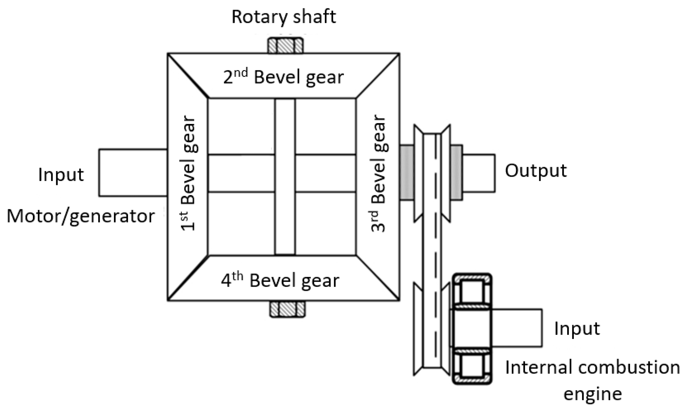
2.1.1. Inverse Differential Gear Power Splitter

The inverse differential gear power splitter used in this study was developed by our group and has been patented [21]. This mechanism has two inputs and one output. These two inputs can be operated independently or integrated with each other. Thus, adequate control of the ICE’s rotational speed and torque load allows operation at optimum fuel efficiency. The setup of the inverse differential gear power splitter in our HEM is illustrated in Figure 1.
When the vehicle system is running with low-power needs, the vehicle can be driven with the motor alone. After distribution by the mechanism, the power delivers twice the torque output, and the output axle’s rotational speed is half that of the motor rotational speed (w1). When the driving load requirement exceeds that provided by the motor power, the vehicle can be switched to ICE mode. The generator’s power output can be controlled according to driving load requirements to keep the ICE in the optimal operating range. The output axle’s rotational speed is one-half the difference of the ICE rotational speed (w3) and the generator rotational speed. When the vehicle is driving at high speed or with high load, the output power cannot meet the vehicle’s actual power needs because the ICE is set to operate in the optimal operating range. Thus, the motor power must be added to compensate for the ICE’s insufficient power output. The output axle’s rotational speed is one-half the sum of the ICE’s rotational speed and the motor’s rotational speed. The operation of the three modes is listed in Table 1.

2.1.2. Integrated Motor/Generator and Lithium Battery Power Module

In our HEM, a modified 3-kW DC brushless motor (Taigene Metal Industry Co., Ltd., Taipei, Taiwan) was used. The specifications (Table 2), T–N curve (Figure 2a) and motor efficiency curve (Figure 2b) of the original Taigene 3-kW DC brushless motor are shown. After modification, the controller had two functions: forward drive and forward/reverse power generation. In order to maximize space utilization and reduce transmission efficiency loss, the integrated motor/generator and inverse differential gear power splitter were directly connected. The lithium battery power module consists of 32 lithium ion batteries (LiFePO4, Lifecell Battery Fty., Guangzhou, Guangdong, China). Each cell had a rated specification of 3.3 V/10 Ah.
The capacity of the battery module was preset as 48 V/20 Ah. The weight of the module was 16.99 kg with a volume of 36.7 × 18.8 × 22 cm3. The charge and discharge current can reach the maximum of 100 A. The module was connected in parallel by two battery packs, each of which was connected in a series by 16 cells. The total voltage of the module after stringing was about 52.8 V. The battery pack had a working range of 36.8 to 58.4 V. Our energy management did not make the battery out of the operation range. In addition, the system was controlled by a battery management system (BMS). It can manage functions including state of charge (SOC) monitoring, low voltage protection, high voltage protection, and over current and over temperature protection. As reported by Sockeel et al. [22], equivalent fuel consumption and battery aging can be accounted by SOC estimation, which can be included in our future study.

2.1.3. Internal Combustion Engine with Continuously Variable Transmission

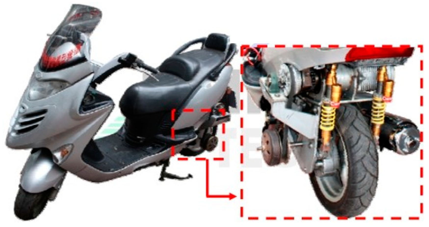
The HEM was modified from a commercial 150-cc ICE motorcycle (GRAND DINK 150, Kwang Yang Motor Co., Ltd., Kaohsiung, Taiwan) which is abbreviated as GRAND DINK in the following article. We removed the traditional pull-rope throttle mechanism to improve the motor rotation throttle and achieve the electronic throttle function. The performance of the engine did not change after modification (Table 3). Superior operating status of this modified engine was obtained according to the brake specific fuel consumption (BSFC) map published previously [23]. In addition, this modified engine was equipped with the CVT mechanism to offer a range of speed reduction ratios from 1.3 to 1.8.
Therefore, the power system of the HEM employed an 8.8 kW ICE and a 3-kW integrated motor/generator. In order to balance the torques between the engine and integrated motor/generator, a set of epicyclic gear train decelerators with a speed reduction ratio of 2.3 were designed and directly connected to the motor axle.

2.2. Power Mode Switching Control Strategy in the Hybrid Electric Motorcycle

Based on the energy management strategy, the HEM has three modes: motor drive mode, ICE drive/generator mode, and dual power drive mode, with different power requirements. The motor drive mode runs at low power, in which the motor alone is used to drive and provide power, which is converted into torque output in two-fold by the inverse differential gear power splitter. The ICE drive/generator mode is used when the driving load exceeds the motor power, in which the ICE is used to drive and optimum performance is maintained by adjusting the generator output according to the driving load. The dual power drive mode is used at high speed or heavy load driving, in which the motor power is added to compensate for the insufficient power output from the ICE, which ran at its best performance. The energy management strategy is depicted in Figure 3. Table 4 lists the abbreviations used in the figure. On the other hand, the brake kinetic energy recycling mode is specific for periods without power requirements. In this mode, the brake’s kinetic energy can be recycled to recharge the battery, thus increasing the driving distance.
The efficiency of ICEs is poor when the vehicle just starts and is at low-speed cruise. Thus, the proper control strategy was to use electricity for the motor drive mode under the speed of 25 km/h. Such a strategy avoids the low-efficiency range of ICEs, achieves the idle-stop objective, and reduces fuel consumption and exhaust emission. However, when the power requirement is higher than the maximum power output of the motor (6000 rpm) and the SOC of the battery is under the lowest limitation (250 mAh), the ICE takes over the power output. After the ICE acted, the increasing rotation speed of ICE gradually approaches stabilization at 6000 rpm, coinciding with the motor rotation speed decreasing.
As the rotation speed of the motor approaches 0 rpm, the motor may switch to the generator mode. The switch can adjust the torque loading so that the ICE can be maintained at the optimal operating range. The ICE drive/generator mode is required while the SOC is under the lowest limitation. The ICE provides power for driving, as well as when the motor runs as a generator and reverses excess kinetic energy to electrical power to batteries. In contrast, when the ICE cannot satisfy the driver’s power needs (11.76 N-m) and the SOC is higher than the lowest limitation, the motor can switch to drive, and the vehicle can enter to the dual power mode.
In an extremely high-power requirement, the maximum power output of ICE is insufficient. The powers of the motor and the ICE can be combined as the dual power mode. The use of the inverse differential gear power splitter can integrate the two powers to achieve dual power output. The motor and the ICE can be maintained in the maximum torque rotation speed range. However, the torque of the two power sources must be on the same level to achieve torque balance. Once the torques from two power sources largely differ, the dual power mode cannot efficiently integrate the power sources. Our practical test revealed that the ICE was maintained at 6000–7000 rpm as the maximum torque value approximately 13 N-m. When the motor was at 2000–6000 rpm, the maximum torque value was higher than 5.6 N-m. After the torque power passed through the epicyclic gear train decelerator, the motor’s torque was magnified to 2.3 times and the maximum torque value exceeded 12.9 N-m. The output powers of ICE and the motor operated in this range can be stably integrated.
While under no power requirement, the system will enter to the brake kinetic energy recycling mode. During brake kinetic energy recycling, electricity is produced. The vehicle’s kinetic energy is converted into electrical power and charged to the battery.

2.3. Experimental Equipment

The overall experimental processes were designed and monitored using LabVIEW (LabVIEW NXG, National Instruments Co., Austin, TX, US). The specifications for simulation are listed in Table 5. A chassis power gauge (CycleDyn, SuperFlow Dynamometers & Flowbenches, Sussex, WI, US) was built-in a 460 V 200 A 75 HP AC motor module roller testing platform. An automotive emission analyzer (MEXA-584L, HORIBA Ltd., Kyoto, Japan) was utilized for measuring the exhaust/pollution emissions, including CO, HC, and CO2. For motor power consumption, a current transducer (HAC 200-S, LEM International SA, Plan les Ouates, Switzerland) was used to measure current signals.

2.4. Test Standards and Specifications

This experiment generally followed the Taiwan E-scooter Standard (TES) [24] and Chinese National Standards (CNS) [25] motorcycle performance testing specifications. The test motorcycle was placed on the chassis power gauge experiment platform to test its acceleration performance and maximum speed. The TES-0A-03-01 regulation was followed for acceleration performance, while TES-0A-02-01 was followed for measuring maximum speed. In order to evaluate the energy consumption of the motorcycles in this study, the CNS 3105:D3029 regulation for Class A motorcycle was followed (Table 6). In this case, the ECE-40 city driving mode was used (Figure 4).

3. Results

The design of the HEM is shown in Figure 5. The following paragraphs will describe the experimental results of our HEM in the ECE-40 driving mode, its energy consumption, and exhaust/pollution emissions.

3.1. ECE-40 Driving Mode Experiment

As shown in Figure 6, the green, dashed line is the curve of the ECE-40 standard driving mode while the line with blue circles is the experimental condition. The error was controlled to within ±5 km/h and the average error was 0.462 km/h.
In the ECE-40 driving mode experiment, the vehicle speed curve in Figure 7 showed that when the speed of the HEM was slower than 25 km/h, all the power was provided by the motor. On the other hand, if the speed was greater than 25 km/h, the ICE took over the power output role. In this mode, after the ICE started, the rotational speed increased to 6000 rpm while the motor’s rotational speed decreased, which is shown in Figure 7. When the rotational speed of the motor was near 0, the system switched to generator mode. At this time, the ICE delivered some of the power to the generator. Then, the motorcycle speed was determined by the control generator’s torque load, which depended on the battery load and recharging current. Owing to physical space limitations, a clutch cannot be installed on the crankshaft output end of the ICE. Therefore, a small speed drop occurred during the rotating acceleration of the ICE and rotating deceleration of the motor, as shown during the 63th and 68th second in the speed curve in Figure 7.
In the third acceleration stage of the ECE-40 driving mode, the power of the ICE was added when the vehicle speed was greater than 25 km/h. However, the power requirement continued to increase during acceleration; thus, the dual power mode was used. After 155 s, the power requirement declined, the motor’s rotation decelerated, and the system switched to the ICE drive/generator mode. After 181 s, power was no longer needed and the vehicle glided forward by inertia. At this time, the system switched to the brake kinetic energy recycling mode. The current of the battery had a negative value and the voltage of the battery increased slightly.

3.2. Vehicle Energy Consumption and Exhaust/Pollution Emission Experiment

In this experiment, the average gasoline consumption and exhaust emissions of the original GRAND DINK and the HEM were compared using the settings of the ECE-40 driving mode. In the ECE-40 driving mode experiment, the actual mileage of the HEM was 1.02 km, which consumed 13.89 g of gasoline. However, the HEM was driven by the motor at low speeds; thus, electricity consumption must be included in the consideration of fuel consumption. In the ECE-40 driving mode experiment, the total electricity consumption was 16.22 Wh, which was converted into 58.392 kJ of energy. The experimental data are summarized in Table 7. The effective gasoline consumption of the HEM was calculated by Equation (1):
Energy   consumption   from   electrocity Energy   density   of   gasoline = 58.392   kJ 44.4   kJ / g = 1.315   g
If total gasoline consumption is equal to actual gasoline consumption plus effective gasoline consumption, we can get 15.205 g. Thus, the average fuel consumption of the HEM was calculated:
Average   fuel   consumption = Actual   mileage   driven Total   gasoline   consumption = 1.02   km 15.205   g = 50.11   km / L
On the other hand, the average fuel consumption of the GRAND DINK was calculated by Equation (3).
Actual   mileage   driven Total   gasoline   consumption = 0.994   km 25.23   g = 29.35   km / L
The fuel consumption improvement ratio was calculated by Equation (4). The average fuel consumption of HEM minus the average fuel consumption of GRAND DINK, and then divided by the average fuel consumption of HEM multiplied by 100%:
50.11 29.35 50.11 = 41.4 %
Under the cold-start setting, the HC and CO emissions from the HEM and GRAND DINK during the ECE-40 driving mode experiment are illustrated in Figure 8 and Figure 9, respectively. In both figures, the green curve represents the GRAND DINK while the blue curve represents our HEM. The HC and CO emissions from our HEM and GRAND DINK both increased by a similar amount during acceleration. Importantly, while the GRAND DINK had significant basal HC and CO emissions, our HEM had much lower basal HC and CO emissions. This is because our HEM was driven by the motor during low-speed driving, which significantly decreased the engine operation time. In this experimental setting, the engine operation time of our HEM accounted for only 40% of total ECE-40 testing time. As a result, the total HC and CO emission was 184,047 ppm and 643.28% for GRAND DINK, and 76,210 ppm and 298.8% for our HEM, respectively. The improvement ratio of exhaust emissions was calculated by Equation (5). All these data are listed in Table 8.
Emission   amount   of   GRAND   DINK Emission   amount   of   HEM Emission   amount   of   GRAND   DINK × 100

4. Discussion

In this section, the energy efficiency analysis and dynamic system response of the HEM are further discussed from the experimental results of the ECE-40 driving mode, energy consumption, and exhaust/pollution emission.

4.1. Energy Efficiency Analyses of the Hybrid Electric Motorcycle

In the ECE-40 driving mode experiment, the ICE of our HEM had an average power output of approximately 0.9 kW, while the rotational speed was maintained at approximately 6000 rpm, which corresponds to 11.76 N-m of torque load. Using the BSFC map, the corresponding BSFC fell within the range of 308–354 g/kW-h, with an average of 331 g/kW-h. Next, the brake thermal efficiency (BTE) of the ICE was calculated by Equation (6)
BTE ( % ) = BHP ( Q × m r ˙ ) / ( 3600 × 1000 ) × 100
where BHP denotes the brake power (kW), BTE denotes the brake thermal efficiency (%), m r ˙ denotes the mass of fuel consumed each hour (g/h), and Q denotes the thermal energy per unit of fuel (gasoline as 44.4 MJ/kg).
In our experiment, the average fuel efficiency was 331 g/kW-h and the average output power was approximately 0.9 kW. Then, BTE was calculated by Equations (7) and (8).
m r ˙ = average   fuel   efficiency × average   output   power = 331   g kW × h × 0.9   kW = 297.9   g / h
BTE ( % ) = 0.9 ( 44400 × 297.9 ) / ( 3600 × 1000 ) × 100 = 24.5 %
Figure 2b shows that the efficiency of the motor can be plotted according to its rotational speed. Based on this conversion, the average operation efficiency of the motor in our HEM during the ECE-40 experiment was 73.2%. In addition, the driving time of the motor was 72.8% of the total driving time, while that of the ICE was 40% (Figure 10). According to these data, the total energy expenditure efficiency was calculated as 55.93%.

4.2. The Response of the Motorcycle Power System

To investigate the power system response of our HEM, we conducted the 0–100 m acceleration performance experiment. According to the TES-0A-03-01 testing regulation for electric motorcycle acceleration performance, if the test vehicle’s power output control has two or more modes (e.g., maximum power mode and regular driving mode), the vehicle must be tested in its maximum power mode. Thus, this experiment was conducted in the dual power driving mode. As shown in Figure 11, the acceleration from 0 to 3.8 s was achieved with the motor power output. Because the motor had superior dynamic response at low rotational speed, the HEM had superior acceleration performance when starting. Power from the ICE was then added to conduct the experiment in the dual power mode. This acceleration experiment was completed in 9.6 s. In TES, 0–100 m acceleration should be completed within 12 s. The acceleration performance of our HEM successfully met the TES.
Figure 12 shows that the HEM accelerated in 1 min with full throttle after starting. In 43–45 s, the vehicle reached the maximum speed of 94.8 km/h. In TES, the maximum speed on a flat road should be greater than 45 km/h. The maximum speed of our HEM also met the TES.
The theoretical maximum vehicle speed of our HEM can be calculated by Equation (9). The specification of our tire was 120/70-12. Thus, the effective radius (r) of the tire was calculated as below.
r = ( 120 × 0.7 ) + ( 12 × 25.4 ) / 2 1000 = 0.2364   m
The rotational speed of power source N is the sum of the ICE’s rotational speed N e and the motor’s rotational speed N m . Under the driving condition with the maximum power requirement, the rotational speed of the ICE was upgraded to 8000 rpm (beyond its optimal operation range) and the rotational speed of the motor was maintained at 6000 rpm. A set of epicyclic gear train decelerators with a speed reduction ratio of 2.3 further decreased the motor rotational speed to approximately 2609 rpm. Thus, the power source’s rotational speed N became 10609 rpm, as shown in Equation (10).
N = N e + N m = 8000 + 6000 2.3 = 10608.7   rpm
The transmission’s total speed reduction ratio (i) is the product of the inverse differential gear power splitter speed reduction ratio 2, CVT speed reduction ratio 1.3, and the final transmission speed reduction ratio 3.5, expressed as Equation (11).
i = 2 × 1.3 × 3.5 = 9.1
Finally, the theoretical maximum vehicle speed was 103.89 km/h after calculation, which was higher than the measured maximum speed of 94.8 km/h. Thus, the transmission efficiency loss of our HEM was 8.75%, which was caused by the slip loss of the CVT transmission belt.

5. Conclusions

In this study, an inverse differential gear and power mode switching control were utilized to develop a HEM. A commercial motorcycle was used as the prototype. An inverse differential gear power splitter integrated and distributed power from the ICE while an integrated motor/generator was used to achieve single/dual power output. For the transmission system, a CVT was used to adjust the transmission speed reduction ratio, thus stabilizing the power output. According to this power mode switching control strategy, actual vehicle tests showed that three types of power modes were achieved. Moreover, the fuel consumption, exhaust/pollution emission, 0–100 m acceleration, and maximum vehicle speed all satisfied the TES. As a result, the following conclusions are drawn:
  • The HEM had three types of power mode switching: (a) motor drive mode; (b) ICE drive/generator mode; and (c) dual power drive mode.
  • The HEM had three advantages. Firstly, idle-stop can be achieved to reduce fuel consumption and exhaust/pollution emissions. The operation of the ICE can be maintained in a better range. Also, the driving endurance of this motorcycle can be extended by energy recycling during braking or deceleration. These advantages explain why this motorcycle had a 41.4% decrease in fuel consumption, and a 58.6% and 53.55% decrease in HC and CO emissions, respectively.
  • The 0–100 m acceleration time of this HEM was 2.4 s less than the TES. Under the dual power drive mode, its maximum speed reached 94.8 km/h, which was 2.1 times greater than the TES. Thus, both tests have met the TES.
  • Theoretical analysis conducted based on experimental data showed that the total energy usage efficiency of the HEM in the ECE-40 driving mode test was 55.93%. For the mechanical transmission efficiency, calculations with the theoretical maximum speed and tested maximum speed showed that the efficiency loss was approximately 8.75%, which was caused by the slip loss of the CVT transmission belt.

Author Contributions

Conceptualization, D.-J.S.; methodology, D.-J.S.; software, D.-J.S.; validation, P.-T.C., D.-J.S. and K.D.H.; formal analysis, D.-J.S.; investigation, D.-J.S.; resources, C.-J.Y.; data curation, D.-J.S.; writing—original draft preparation, P.-T.C. and C.-J.Y.; writing—review and editing, P.-T.C. and C.-J.Y.; visualization, D.-J.S.; supervision, C.-J.Y. and K.D.H.

Funding

P.-T.C. is thankful for the financial support from the Center of Atomic Initiative for New Materials, National Taiwan University, from the Featured Areas Research Center Program within the framework of the Higher Education Sprout Project by the Ministry of Education in Taiwan (108L9008).

Conflicts of Interest

The authors declare no conflict of interest.

References

  1. Environmental Protection Administration Taiwan. Vehicular Air Pollutant Emission Standards 2017. Available online: https://law.moj.gov.tw/ENG/LawClass/LawAll.aspx?pcode=O0020003 (accessed on 14 March 2019).
  2. Chen, P.-T.; Pai, P.-H.; Yang, C.-J.; Huang, K.D. Development of Transmission Systems for Parallel Hybrid Electric Vehicles. Appl. Sci. 2019, 9, 1538. [Google Scholar] [CrossRef]
  3. Huang, K.D.; Sangeetha, T.; Cheng, W.-F.; Lin, C.; Chen, P.-T. Computational Fluid Dynamics Approach for Performance Prediction in a Zinc–Air Fuel Cell. Energies 2018, 11, 2185. [Google Scholar] [CrossRef]
  4. Sangeetha, T.; Chen, P.-T.; Cheng, W.-F.; Yan, W.-M.; Huang, K.D. Optimization of the Electrolyte Parameters and Components in Zinc Particle Fuel Cells. Energies 2019, 12, 1090. [Google Scholar] [CrossRef]
  5. Piaggio MP3 125 Hybrid Ibrido Workshop Service. Available online: https://anyfreepdf.com/lib/piaggio-mp3-125-hybrid-ibrido-workshop-service.pdf?web=maxfield-preprod.marketing-electronique.fr (accessed on 14 March 2019).
  6. Annual Report 2009-Yamaha Motor Global. Available online: https://global.yamaha-motor.com/ir/annual/pdf/2009/2009annual-e.pdf (accessed on 14 March 2019).
  7. PGO Motive Power. Available online: http://www.pgo.com.tw/index.php (accessed on 14 March 2019).
  8. Hsu, Y.-Y.; Lu, S.-Y. Design and Implementation of a Hybrid Electric Motorcycle Management System. Appl. Energy 2010, 87, 3546–3551. [Google Scholar] [CrossRef]
  9. Morandin, M.; Ferrari, M.; Bolognani, S. Power-Train Design and Performance of a Hybrid Motorcycle Prototype. IEEE Trans. Ind. Appl. 2013, 51, 2216–2226. [Google Scholar] [CrossRef]
  10. Walker, P.D.; Roser, H.M. Energy consumption and cost analysis of hybrid electric powertrain configurations for two wheelers. Appl. Energy 2015, 146, 279–287. [Google Scholar] [CrossRef]
  11. Chung, C.-T.; Hung, Y.-H. Performance and energy management of a novel full hybrid electric powertrain system. Energy 2015, 89, 626–636. [Google Scholar] [CrossRef]
  12. Kebriaei, M.; Niasar, A.H.; Asaei, B. Hybrid Electric Vehicles: An Overview. In Proceedings of the 2015 International Conference on Connected Vehicles and Expo (ICCVE), Shenzhen, China, 19–23 October 2015; pp. 299–305. [Google Scholar]
  13. Hung, Y.-H.; Chang, S.-W.; Hsiao, W.-T.; Huang, S.-T.; Wang, L.-J.; Chung, C.-T. Mechanical Designs, Energy Management, and Performance Assessment of a Novel Hybrid Electric Scooter. In Proceedings of the IEEE International Conference on Advanced Materials for Science and Engineering (ICAMSE 2016), Tainan, Taiwan, 12–13 November 2016; pp. 88–91. [Google Scholar]
  14. Masih-Tehrani, M.; Dahmardeh, M. A Novel Power Distribution System Employing State of Available Power Estimation for a Hybrid Energy Storage System. IEEE Trans. Ind. Electron. 2018, 65, 6676–6685. [Google Scholar] [CrossRef]
  15. Nguyen, V.-T.; Hwang, P.; Huynh, T. Computational analysis on Hybrid Electric Motorcycle with front wheel electric motor using Lithium Ion battery. In Proceedings of the 2017 International Conference on System Science and Engineering (ICSSE), Ho Chi Minh City, Vietnam, 21–23 July 2017; pp. 355–359. [Google Scholar]
  16. Sanli, A.E.; Yilmaz, E.S.; Ozden, S.K.; Gordesel, M.; Gunlu, G. A Direct Borohydride-Peroxide Fuel Cell-LiPO Battery Hybrid Motorcycle Prototype e II. Int. J. Hydrogen Energy 2017, 43, 992–1005. [Google Scholar] [CrossRef]
  17. Farzaneh, A.; Farjah, E. Analysis of Road Curvature’s Effects on Electric Motorcycle Energy Consumption. Energy 2018, 151, 160–166. [Google Scholar] [CrossRef]
  18. Abu Hanifah, R.; Toha, S.F.; Hanif, N.H.H.M.; Kamisan, N.A.; Hanif, N.H.H.M. Electric Motorcycle Modeling for Speed Tracking and Range Travelled Estimation. IEEE Access 2019, 7, 26821–26829. [Google Scholar] [CrossRef]
  19. Chen, P.-T.; Yang, F.-H.; Sangeetha, T.; Gao, H.-M.; Huang, K.D. Moderate Energy for Charging Li-Ion Batteries Determined by First-Principles Calculations. Batter. Supercaps 2018, 1, 209–214. [Google Scholar] [CrossRef]
  20. Chen, P.-T.; Yang, F.-H.; Cao, Z.-T.; Jhang, J.-M.; Gao, H.-M.; Yang, M.-H.; Huang, K.D. Reviving Aged Lithium-Ion Batteries and Prolonging Their Cycle Life by Sinusoidal Waveform Charging Strategy. Batter. Supercaps 2019, accepted. [Google Scholar] [CrossRef]
  21. Huang, K.D.; Lin, G.G. Vehicle Parallel Power Integration Distribution Mechanism. China Patent I318938, 1 January 2010. [Google Scholar]
  22. Sockeel, N.; Shahverdi, M.; Mazzola, M. Impact of the State of Charge estimation on Model Predictive Control Performance in a Plug-in Hybrid Electric Vehicle Accounting for Equivalent Fuel Consumption and Battery Aging. In Proceedings of the Transportation Electrification Conference and Expo (ITEC), Detroit, MI, USA, 19–21 June 2019. [Google Scholar]
  23. Chang, C.H. Evaluation of Performance and Development of User Interface for the Parallel Hybrid Electric Heavy Motorcycle System. Master’s Thesis, Department of Vehicle Engineering, Dayeh University, Changhua, Taiwan, 2006. [Google Scholar]
  24. Taiwan E-Scooter Standard (TES). Ministry of Economic Affairs, R.O.C. Available online: https://www.lev.org.tw/default.asp (accessed on 14 March 2019).
  25. Chinese National Standards (CNS). CNS 3105:D3029, Method of Test Fuel Consumption for Motorcycle; Chinese National Standards: Taipei, Taiwan, 2001. [Google Scholar]
Figure 1. Inverse differential gear power splitter used in the proposed hybrid electric motorcycle (HEM).
Applsci 09 01787 g001
Figure 2. Motor rotational speed and (a) torque performance curve (b) efficiency curve of TAIGENE 3-kW DC brushless motor.
Applsci 09 01787 g002
Figure 3. Energy management strategy flow.
Applsci 09 01787 g003
Figure 4. ECE-40 city driving mode; ECE-40: automobile regulations defined by Economic Commission of Europe.
Applsci 09 01787 g004
Figure 5. Inverse differential gear type HEM.
Applsci 09 01787 g005
Figure 6. ECE-40 driving mode experiment.
Applsci 09 01787 g006
Figure 7. Experimental results of the ECE-40 driving mode.
Applsci 09 01787 g007
Figure 8. Hydrocarbon (HC) exhaust/pollution emission from our HEM (blue) and the GRAND DINK (green) after a cold start in the ECE-40 driving mode test.
Applsci 09 01787 g008
Figure 9. Carbon oxide (CO) exhaust/pollution emission from our HEM (blue) and the GRAND DINK (green) after a cold start in the ECE-40 driving mode test.
Applsci 09 01787 g009
Figure 10. The driving period of the motor (green) and the ICE (orange) used by our HEM in the ECE-40 driving experiment.
Applsci 09 01787 g010
Figure 11. The 0–100 m acceleration performance of our HEM.
Applsci 09 01787 g011
Figure 12. The maximum vehicle speed performance of our HEM.
Applsci 09 01787 g012
Table 1. Inverse differential gear power splitter rotation speed relationship; ICE: internal combustion engine.
Operation ModeMotor/Generator Rotational SpeedICE Rotational SpeedOutput Axle Rotational Speed
Mode 1w10w1/2
Mode 2−w1w3(w3 − w1)/2
Mode 3w1w3(w3 + w1)/2
Table 2. The specification of the TAIGENE 3-kW DC brushless motor.
MotorTAIGENE BLM-J48
Voltage48 V
Core poles (N)8 poles
Torque constant (K)0.74 N-m/A
Voltage constant0.0076 V/rpm
Maximum speed6000 rpm
Maximum torque6 N-m
Motor resistance (R)0.014 Ω
Power3000 W
Table 3. ICE specifications.
ItemSpecification
Displacement149.5 cc
Ignition typeCapacitor discharge ignition
Compression ratio10.6:1
Maximum output8.8 kW at 7500 rpm
Maximum torque/11.76 N-m at 6000 rpm
Cooling typeWater cooling
Table 4. Definition of abbreviations in the energy management; SOC: state of charge.
ItemDescription
PDVehicle demand total power
PeOutput power of ICE
Pe1The optimal operating zone
Pe2The 2nd optimal operating zone
PmOutput power of motor
Pm-maxMaximum output power of motor
SOCState of charge
SOCBBase value of SOC
SOCLPreset minimum residual capacity
SOCHPreset maximum residual capacity
VBBattery voltage
VGGenerator output voltage
VB0Initial battery voltage
ΔVVG − VB
XValue for power switch
AInput of starting value
Table 5. Specifications of experimental equipment.
SuperFlow CycleDyn Chassis Power GaugeSpecification
Power460 V, AC 200 A
Power gauge type75 hp AC motor type
Maximum tested vehicle speed320 km/h
Maximum measuring scope0–500 hp
Maximum axle load455 kg
Vehicle weight simulation scope23–568 kg
Torque measuring accuracy<0.2%
Speed measuring accuracy0.016 km/h
Distance measuring accuracy0.5 m
HORIBA MEXA-584L Exhaust Analyzer
Power100–240 V, AC 50/60 Hz
External size260 × 357 × 157 (mm3)
Weight4 kg
Gas measuredCO, HC, and CO2
Warm-up time5 min
Environmental conditions0–45 °C, relative humidity <90%
Communication interfaceRS-232
The LEM HAC 200-S Current Sensor
Power±15 V ±5%, DC ±18 mA
Weight70 g
Measuring range±600 A
Output voltage±4 V
Environmental conditions−10~80 °C
Accuracy±1%
Table 6. Time distribution for each segment of the Class A motorcycle driving mode.
SegmentTime (sec)Percentage (%)
Idling6020.8
Deceleration94.6
Acceleration4221.5
Set speed5729.2
Deceleration2713.9
Total195100
Table 7. Fuel consumption data of the HEM and GRAND DINK; HEM: our developed hybrid electric motorcycle; GRAND DINK: the ICE motorcycle manufactured by Kwang Yang Motor Co., Ltd.
GRAND DINKHEM
Actual driven mileage0.994 km1.02 km
Fuel consumption25.3 g15.205 g
Average fuel consumption29.35 km/L50.11 km/L
Table 8. Exhaust emission data of our HEM and the GRAND DINK.
GRAND DINKHEM
COtotal643.28%298.8%
HCtotal184,047 ppm76,210 ppm
CO emission improvement ratio-53.55%
HC emission improvement ratio-58.6%

