The Resistance of Welded Joints of Galvanized RHS Trusses with Different Vent Hole Geometries

 ,
,  ,
, 
Abstract
:Featured Application
Abstract
1. Introduction
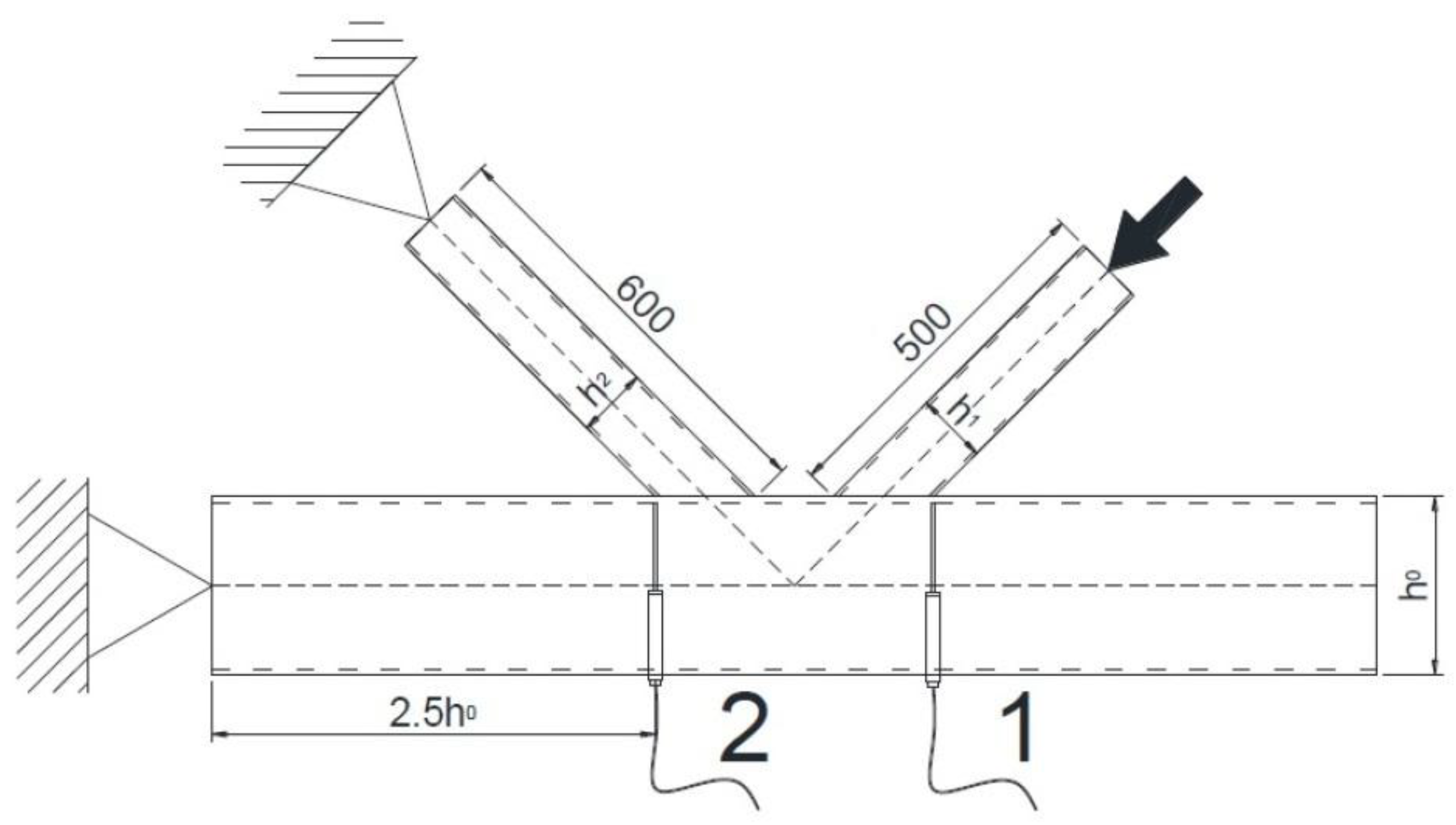
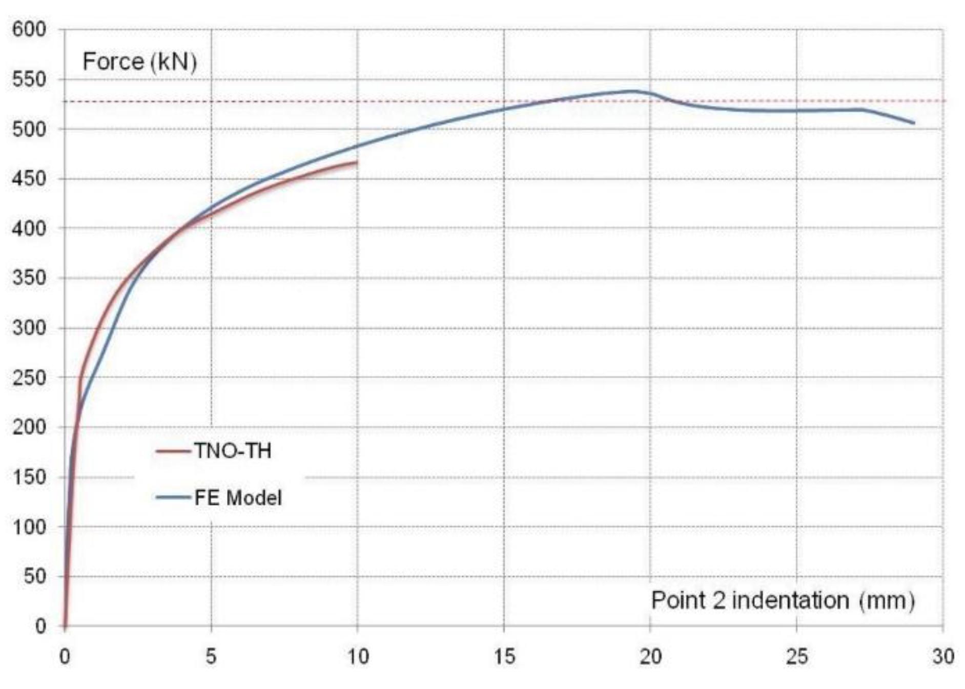
- The numerical model needed to be validated against experimental results. For this purpose, the main source of experimental values for the development of design equations for welded joints of RHS trusses (i.e., the Delft University test reports) was used. Six tests on K gap joints between RHS were selected, because their observed failure was related to the so-called “brace failure” of K welded joints between RHS, which involves both the effective width failure and the local buckling failure on the brace elements. This is because they are clearly the failure modes that are expected to be more influenced by the presence of holes in the brace.
- As is clearly stated in the bibliography, in most cases, weld geometry must be modeled in situations where the gaps between the braces are important. However, this was not really modeled in the previous work mentioned, which only considered an estimation of the thermal effects of the weld process. This lack of geometrical weld modeling is solved in this new paper, and the thermal effects mentioned were neglected, since neither the bibliography nor the previous work carried out by the authors [24] showed any appreciable influence of this factor.
- The general design of the experiment presented in the previous work was not specifically focused on failure modes that could be more greatly affected by the vent holes. Nevertheless, in the present paper, a parametric study has been designed by selecting joints that, according to the design equations, could represent “brace failure” or, in some cases, the “chord face failure”, which is very close to a “brace failure”.
- The brace lengths in the models of the previous work led to brace buckling in some cases, but not local buckling at the connection location. The brace lengths were reduced in the present work to ensure that the results really showed joint failures.
- Elliptical holes were not considered in this work, because they are impractical.
- Finally, in this new paper, not only K-joints, but also N-joints were considered.
2. Finite Element Modeling
3. Validation of Finite Element Modeling
4. Parametric Study of K- and N-joints Results and Discussion
5. Conclusions
- -
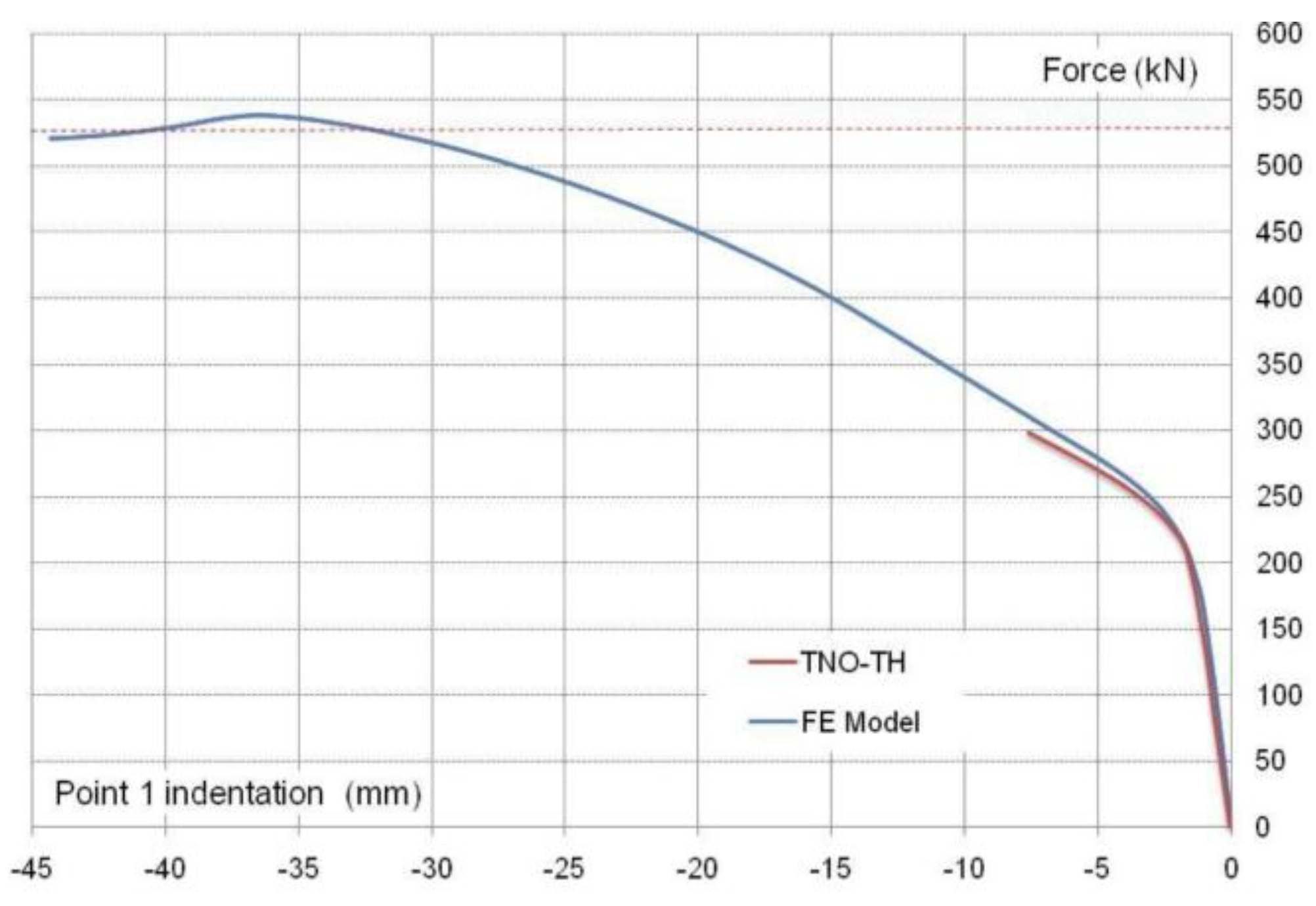
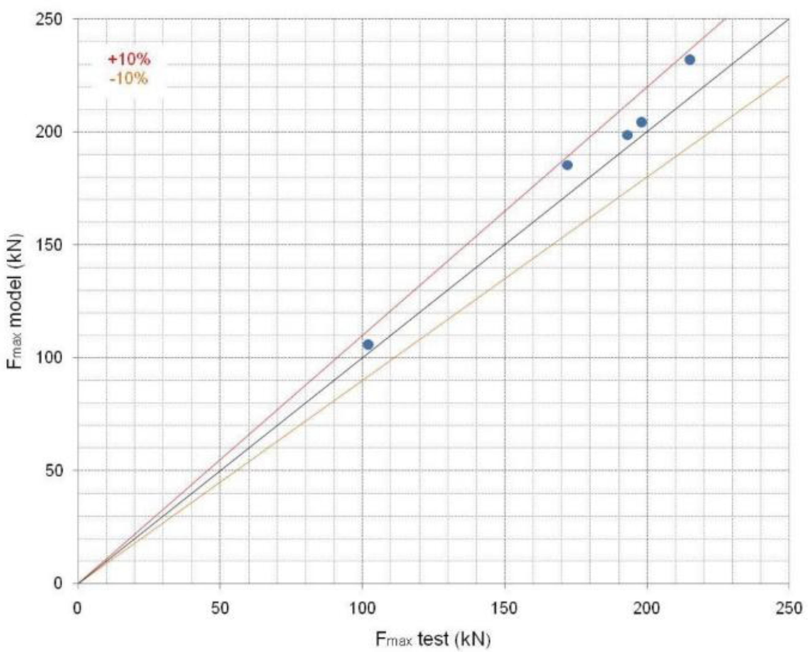
- The developed FE simulation accurately reproduced the actual behavior of the analyzed joints, showing good agreement with the experimental results when the welds were modeled. Therefore, this model, based on shell elements, is adequate for simulating the RHS K- and N-joints in lattice girders and for predicting the strength and stiffness when fracture in welds can be avoided.
- -
- There is a reasonable agreement with the Eurocode equations, confirming that FEA is a useful tool for obtaining appropriate results regarding joint behavior.
- -
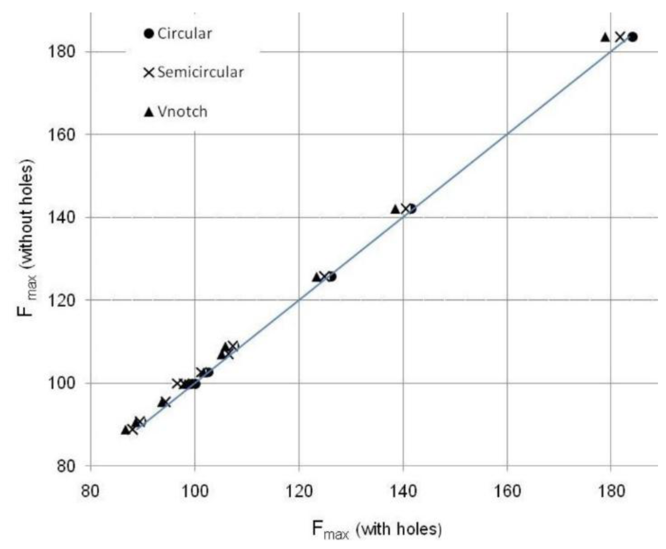
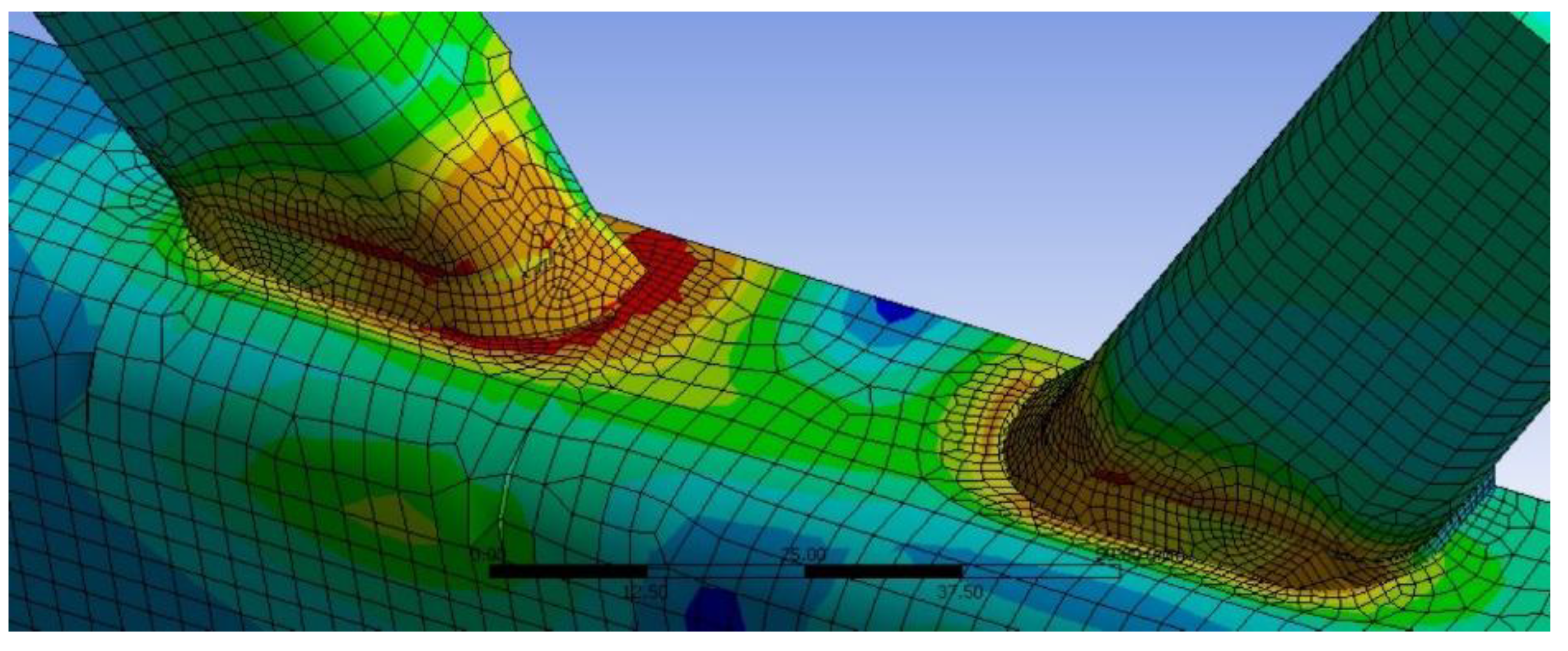
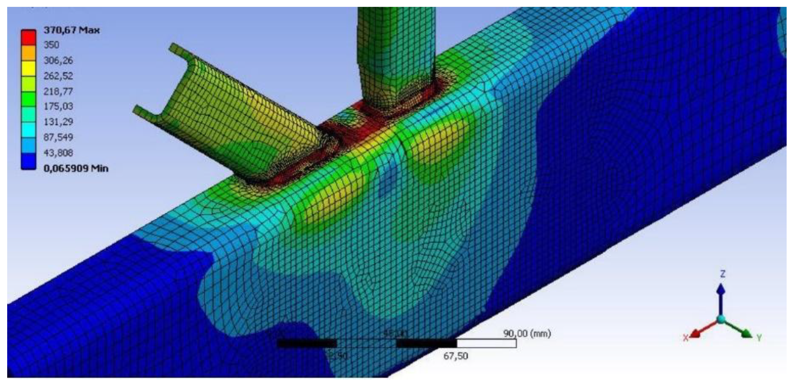
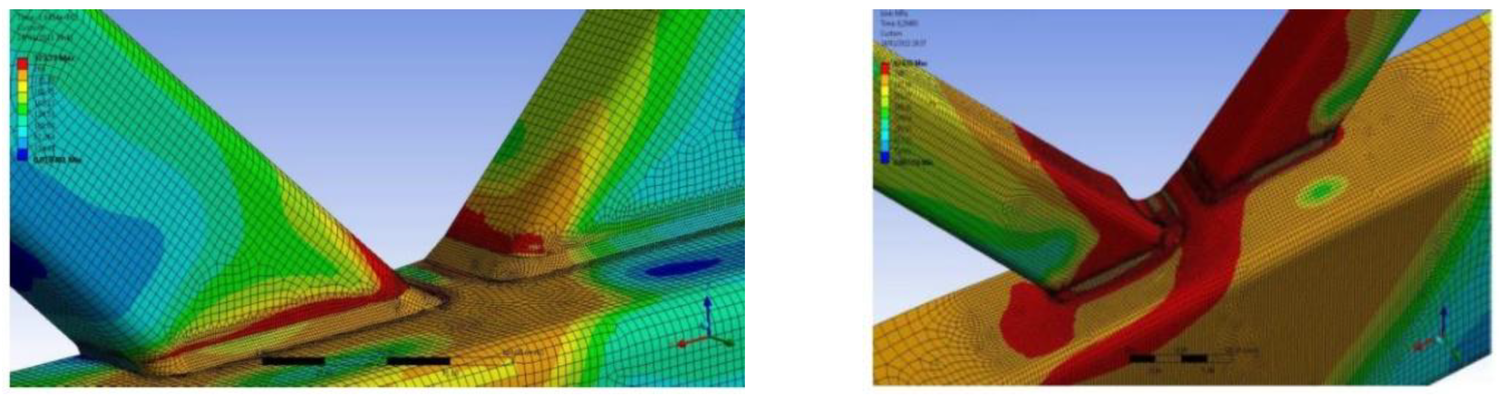
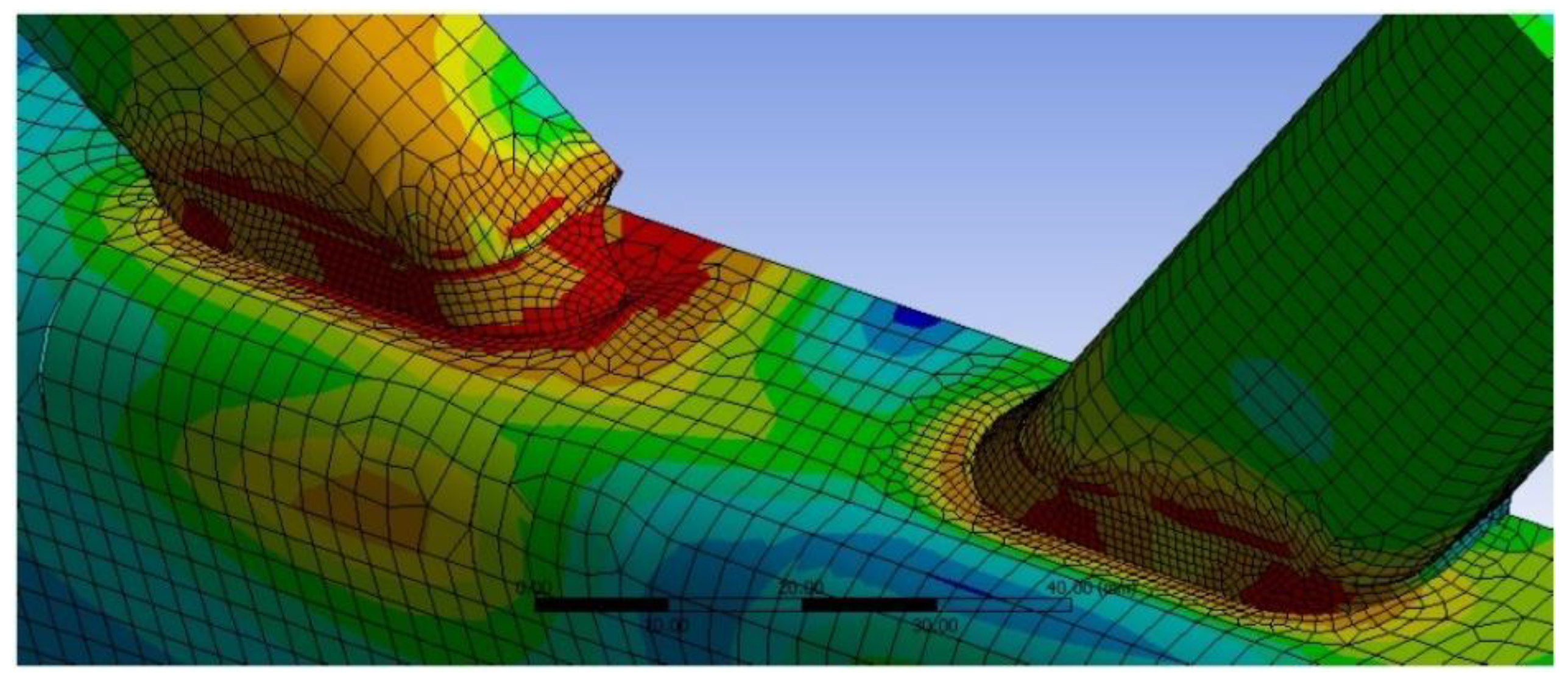
- In the numerical simulation, different combined failure modes were observed, but these were never dependent on the presence of a vent hole or on the shape of the vent hole.
- -
- The local buckling present in a brace failure occurs away from the vent holes and the welds; therefore, in these cases, the presence of holes has no influence on joint resistance.
- -
- If the thickness ratio between the brace and the chord results in chord plastification, the effect of the presence of a hole is also negligible with respect to joint resistance.
- -
- The presence of a ventilation hole for the hot-dip galvanizing process such as those considered in this study does not significantly affect the joint resistance.
- -
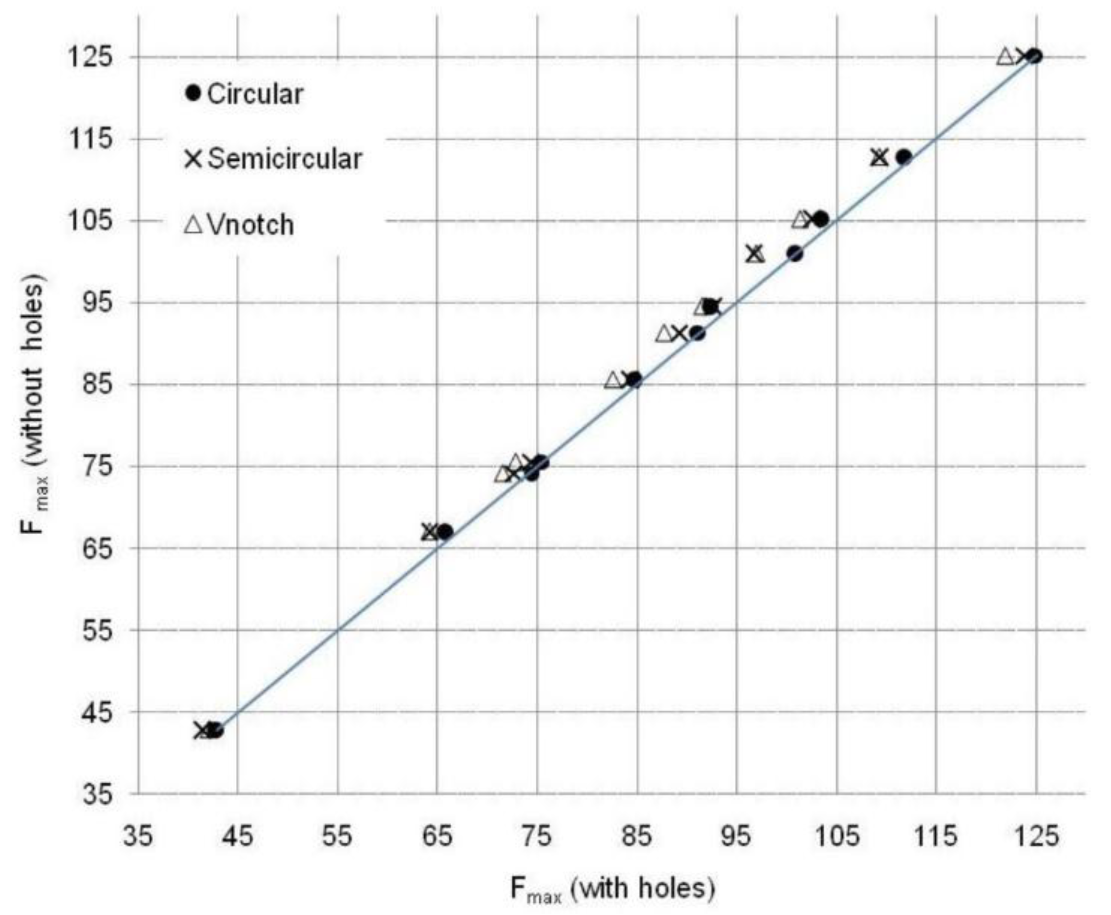
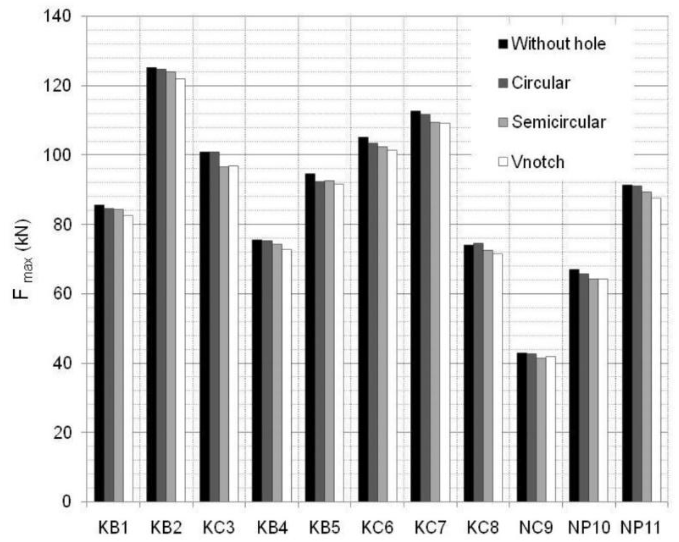
- Based on the small differences observed for joint resistance, it is possible to affirm that it does not matter what type of vent holes are used for the galvanization process. All the analyzed hole shapes presented fair performance in terms of the mechanical strength of the joint. Although the shapes that cut the brace-chord weld exerted slightly more influence over the resistance than holes at some distance, all of them could be proposed to be valid solutions for machining vent holes.
- -
- Taking into account the above-mentioned conclusions, we can offer some recommendations for engineers when designing galvanized lattice girders with RHS. They may choose any of the considered vent hole configurations, observing only the suggested filling areas. Therefore, certain preferences throughout the manufacturing process could be reasons for making a final decision.
Author Contributions
Funding
Acknowledgments
Conflicts of Interest
Nomenclature
| HDG | hot-dip galvanizing |
| HSS | hollow structural section |
| RHS | rectangular hollow section |
| SHS | square hollow section |
| b | width of the hollow section |
| h | depth of the hollow section |
| t | thickness of the hollow section |
| g | gap of the joint |
| β | ratio of widths (bi/b0) |
| γ | ratio (b0/(2t0)) |
| fu | ultimate strength |
| fy | yield strength |
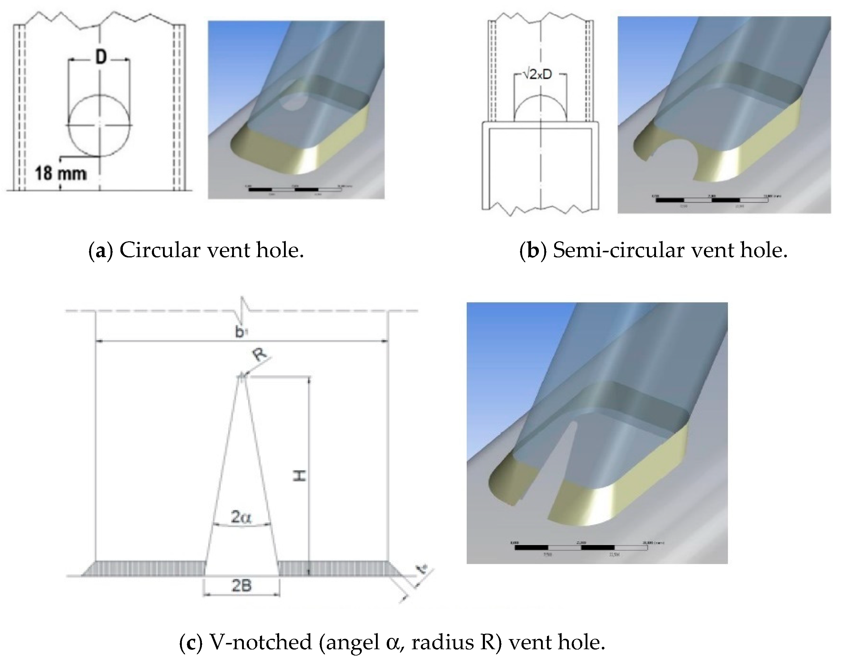
| D | circular vent hole diameter |
| H | height of V-notched vent hole |
| B | half opening of V-notched vent hole |
| R | radius of V-notched vent hole |
| α | half angle of V-notched vent hole |
| tw | weld throat |
| εact, | actual strain |
| εeng, | engineering strain |
| σeng, | engineering stress |
| σact, | actual stress |
| Subscripts | |
| i | denoting the brace |
| o | denoting the chord |
| act. | actual value |
| eng. | engineering value |
References
- Glinde, H. Galvanizing Explained. The Misunderstood Process; Hot Dip Galvanizing Magazine; Galvanizers Association: Birmingham, UK, 2013. [Google Scholar]
- American Galvanizers Association. Galvanize It! Online seminar: ‘Sustainable development & hot-dip galvanizing’. Available online: http://www.galvanizeit.org/sustainable-development-and-hot-dip-galvanizing (accessed on 1 February 2018).
- Cornish, R. General Galvanizing in North America-Association, key metrics and markets. In Proceedings of the Proceedings of 9th Asia Pacific General Galvanizing Conference, Singapore, 1–2 November 2018. [Google Scholar]
- CEN, EN-1993-1-8:2005, Eurocode 3: Design of Steel Structures. Part 1–8; European Committee for Standardization: Brussels, Belgium, 2005; ISBN 978-3-433-03216-9.
- AISC. Specification for Structural Steel Buildings; ANSI/AISC 360-10; American Institute of Steel Construction: Chicago, IL, USA, 2010. [Google Scholar]
- AWS D1.1/D1.1 M: Structural Welding Code-Steel, 22th ed.; American Welding Society: Miami, FL, USA, 2010.
- CEN, EN-10219-2:2006 Cold Formed Welded Structural Hollow Sections of Non-Alloy and Fine Grain Steels. Part 1: Technical Delivery Conditions; Part 2: Tolerances, Dimensions and Sectional Properties; European Committee for Standardization: Brussels, Belgium, 2006.
- CEN, EN-10210-2:2006 Hot Finished Structural Hollow Sections of Non-Alloy and Fine Grain Steels. Part 1: Technical Delivery Conditions; Part 2: Tolerances, Dimensions and Sectional Properties; European Committee for Standardization: Brussels, Belgium, 2006.
- Packer, J.A.; Wardenier, J.; Zhao, X.L.; Van der Vegte, G.J.; Kurobane, Y. Design Guide 3 for Rectangular Hollow Section (RHS) Joints under Predominantly Static Loading, 2nd ed.; LSS Verlag: Köln, Germany, 2009. [Google Scholar]
- Packer, J.A.; Henderson, J.E. Hollow Structural Section Connections and Trusses, A Design Guide; Canadian Institute of Steel Construction: Markham, ON, Canada, 1997. [Google Scholar]
- Dutta, D.; Wardenier, J.; Yeomans, N.; Sakae, K.; Bucak, Ö.; Packer, J.A. Design Guide 7: For Fabrication, Assembly and Erection of Hollow Section Structures; TÜV-Verlag: Cologne, Germany, 1998. [Google Scholar]
- IIW, 2009. Static Design Procedure for Welded Hollow Section Joints—Recommendations, 3rd ed.; Commission XV, IIW Doc. XV-1329-09, IIW Annual Assembly; International Institute of Welding: Singapore, 2009. [Google Scholar]
- Wardenier, J.; Packer, J.A.; Zhao, X.L.; Van der Vegte, G.J. Hollow Sections in Structural Applications, 2nd ed.; Bouwen Met Staal: Rotterdam, The Netherlands, 2010. [Google Scholar]
- Wardenier, J. Hollow Section Joints; Delft University Press: Delft, The Netherlands, 1982. [Google Scholar]
- Puthli, R.; Packer, J.A. Structural design using cold-formed hollow sections. Steel Constr. 2013, 6, 150–157. [Google Scholar] [CrossRef]
- Ritakallio, P.O. Cold-formed high-strength tubes for structural applications. Steel Constr. 2012, 5, 158–167. [Google Scholar] [CrossRef]
- Cook, M. European General Galvanizers Association. Galvanizing in the European Union. In Proceedings of the Congresso Brasileiro de Galvanizaçao ‘GalvaBrasil Conference’, Sao Paulo, Brazil, 22–23 October 2013. [Google Scholar]
- Zedet, A. European General Galvanizers Association. Challenges and Prospects for General Galvanizing in Europe. In Proceedings of the 9th Asia Pacific General Galvanizing Conference, Singapore, 8–11 September 2013. [Google Scholar]
- Langill, T.J. Mechanical Properties of Hot-Dip Galvanized Steel. In Proceedings of the American Society of Civil Engineers Congress, Structures, Austin, TX, USA, 24–27 June 2009. [Google Scholar]
- Coni, N.; Gipiela, M.L.; D’Oliveira, A.S.C.M.; Marcondes, P.V.P. Study of the Mechanical Properties of the Hot Dip Galvanized Steel and Galvalume. J. Braz. Soc. Mech. Sci. Eng. 2009, 31, 319–326. [Google Scholar] [CrossRef]
- Feldmann, M.; Pinger, T.; Schäfer, D.; Pope, R.; Smith, W.; Sedlacek, G. Hot-Dip-Zinc-Coating of Prefabricated Structural Steel Components; JRC Scientific and Technical Reports; European Commission: Brussels, Belgium, 2010. [Google Scholar]
- Sun, M.; Packer, J.A. Hot-dip galvanizing of cold-formed steel hollow sections: A state-of-the-art review. Front. Struct. Civ. Eng. 2019, 13, 49–65. [Google Scholar] [CrossRef]
- Berto, F.; Mutignani, F.; Pitarello, L. Effect of hot-dip galvanization on the fatigue behaviour of structural steel. In Proceedings of the 21st European Conference on Fracture, Procedia Structural Integrity, Catania, Italy, 20–24 June 2016. [Google Scholar]
- Lozano, M.; Serrano, M.A.; López-Colina, C.; Gayarre, F.L.; Suárez, J. The Influence of the Heat-Affected Zone Mechanical Properties on the Behaviour of the Welding in Transverse Plate-to-Tube Joints. Materials 2018, 11, 266. [Google Scholar] [CrossRef] [PubMed]
- Landa, P.; Iglesias, G. Cidect Project 14B. Monograph on Hot-Dip Galvanized Tubular Structures: Design Recommendations for Holes Due to Galvanizing Process. Available online: http://www.cidect.org/en/Research_Projects/ (accessed on 17 August 2018).
- Serrano, M.A.; López-Colina, C.; Iglesias, G. Cidect project 5BX. Static Strength of RHS K-Joints in Which Brace Members May be Affected by Vent Holes for Truss Hot-Dip Galvanizing, Final Report. Available online: http://www.cidect.org/en/Research_Projects/ (accessed on 17 August 2018).
- Serrano-López, M.A.; López-Colina, C.; del Coz-Díaz, J.J.; Gayarre, F.L. Static behavior of compressed braces in RHS K-joints of hot-dip galvanized trusses. J. Constr. Steel Res. 2013, 89, 307–316. [Google Scholar] [CrossRef]
- del Coz, D.; Serrano-López, M.A.; López-Colina Pérez, C.; Álvarez Rabanal, F.P. Effect of the vent hole geometry and welding on the static strength of galvanized RHS K-joints by FEM and DOE. Eng. Struct. 2012, 41, 218–233. [Google Scholar] [CrossRef]
- Lee, M.M.K. Strength, stress and fracture analyses of offshore tubular joints using finite elements. J. Constr. Steel Res. 1999, 51, 265–286. [Google Scholar] [CrossRef]
- Lee, M.M.K.; Dexter, E.; Kirkwood, M. Strength of moment-loaded tubular T/Y-joints in offshore platforms. Struct. Eng. 1995, 73, 239–246. [Google Scholar]
- Lalani, M. Post-yield and post-peak behaviour of tubular joints in offshore structures. In Proceedings of the 5th international Symposium on Tubular Structures, Nottingham, UK, 25–27 August 1993; pp. 446–454. [Google Scholar]
- Van der Vegte, G.J.; De Konig, C.M.H.; Puthli, R.S.; Wardenier, J. Numerical simulations of experiments on multiplanar tubular steel X-joints. Int. J. Offshore Polar Eng. 1991, 1(3). Document ID: ISOPE-91-01-3-200. [Google Scholar]
- Lee, M.M.K.; Wilmshurst, S.R. Numerical modelling of CHS joints with multiplanar double-K configuration. J. Constr. Steel Res. 1995, 32, 281–301. [Google Scholar] [CrossRef]
- Suo, Y.; Yang, W.; Chen, P. Study on Hysteresis Model of Welding Material in Unstiffened Welded Joints of Steel Tubular Truss Structure. Appl. Sci. 2018, 8, 1701. [Google Scholar] [CrossRef]
- López-Colina, C.; Serrano-López, M.A.; López-Gayarre, F.; Suárez, F.J. Resistance of the component ‘lateral faces of RHS’ at high temperature. Eng. Struct. 2010, 32, 1133–1139. [Google Scholar] [CrossRef]
- López-Colina, C.; Serrano-López, M.A.; López-Gayarre, F.; del Coz Díaz, J.J. Stiffness of the component ‘lateral faces of RHS’ at high temperature. J. Constr. Steel Res. 2011, 67, 1835–1842. [Google Scholar] [CrossRef]
- López-Colina, C.; Serrano, M.A.; Gayarre, F.L.; González, J. The component ‘lateral faces of RHS’ under compression at ambient and high temperature. Int. J. Steel Struct. 2014, 14, 13–22. [Google Scholar] [CrossRef]
- Serrano-López, M.A.; López-Colina, C.; González, J.; López-Gayarre, F. A Simplified FE Simulation of Welded I Beam-to-RHS Column Joints. Int. J. Steel Struct. 2016, 16, 1095–1105. [Google Scholar] [CrossRef]
- Van der Vegte, G.J.; Wardenier, J.; Puthli, R.S. FE analysis for welded hollow-section joints and bolted joints. Struct. Build 2010, 163, 427–437. [Google Scholar] [CrossRef]
- Wardenier, J.; De Koning, C.H.M. Rig Comparison Tests for Welded Joints; Cidect Project 5S-76-33, TNO; The University of Delft: Delft, The Netherlands, 1976. [Google Scholar]
- Wardenier, J.; Stark, J.W.B. The Static Strength of Welded Lattice Girder Joints in Structural Hollow Sections, Revised Final Report; Cidect Project 5Q/78/4, TNO; The University of Delft: Delft, The Netherlands, 1978. [Google Scholar]
- Yang, W.; Lin, J.; Gao, N.; Yan, R. Experimental Study on the Static Behavior of Reinforced Warren Circular Hollow Section (CHS) Tubular Trusses. Appl. Sci. 2018, 8, 2237. [Google Scholar] [CrossRef]
- Outinen, J.; Kaitila, O.; Mäkeläinen, P. Finite Element Modeling of Cold-Formed Steel Members at High Temperature; Helsinki University of Technology Laboratory of Steel Structures Publications: Helsinki, Finland, 2002. [Google Scholar]
- López-Colina, C.; Serrano, M.A.; Lozano, M.; Gayarre, F.L.; Suárez, J. Simplified Models for the Material Characterization of Cold-Formed RHS. Materials 2017, 10, 1043. [Google Scholar] [CrossRef] [PubMed]
- Lu, L.H.; De Winkel, G.D.; Yu, Y.; Wardenier, J. Deformation limit for the ultimate strength of hollow section joints. In Proceedings of the 6th ISTS, Tubular Structures VI, Melbourne, Australia, 14–16 December 1994. [Google Scholar]
- Serrano-López, M.A.; López-Colina, C.; Lozano, A.; Iglesias, G.; González, J. Influence of the angle in the strength of RHS K-joints in galvanized lattice girders. In Proceedings of the 14th ISTS, Tubular Structures XIV, London, UK, 12–14 September 2012; pp. 113–120. [Google Scholar]


| Test No | Gap (g/b0) | Joint Members | fy [N/mm2] | fu [N/mm2] | Tangent Modulus [N/mm2] |
|---|---|---|---|---|---|
| 1 | 0.10 | Chord: 258 × 258 × 8.4 Comp. Brace: 99.4 × 99 × 6.0 Tension Brace: 103 × 99 × 5.2 | 289 337 317 | 409 402 405 | 1110 802 932 |
| 2 | 0.43 | Chord: 100 × 100 × 3.8 Braces: 40 × 40 × 4.0 | 261 279 | 363 383 | 963 996 |
| 3 | 0.15 | Chord: 100 × 100 × 4.1 Braces: 60 × 60 × 4.2 | 462 443 | 512 587 | 1291 1813 |
| 4 | 0.15 | Chord: 99.8 × 99.8 × 4.3 Braces: 59.7 × 59.7 × 4.4 | 333 376 | 373 411 | 907 958 |
| 5 | 0.10 | Chord: 102 × 102 × 3.9 Braces: 64 × 64 × 3.3 | 363 369 | 520 511 | 1440 1350 |
| 6 | 0.10 | Chord: 102 × 102 × 4.2 Braces: 64 × 64 × 4.0 | 321 349 | 501 401 | 1550 729 |
| Joint | 2 | 3 | 4 | 5 | 6 |
|---|---|---|---|---|---|
| Test [kN] | 102 | 215 | 172 | 198 | 193 |
| Model [kN] | 105.9 | 232.1 | 185.3 | 204.3 | 198.6 |
| Deviation % | 3.8 | 7.9 | 7.7 | 3.2 | 2.9 |
| Joint | Chord RHS (b0 × h0 × t0) | Braces SHS (b1 × t1) | β (b1/b0) | γ (b0/2t0) | Gap [mm] | (g/b0) | Angle [°] |
|---|---|---|---|---|---|---|---|
| KB1 | 60 × 80 × 5 | 30 × 3 | 0.5 | 6 | 37.6 | 0.62 | 45 |
| KB2 | 60 × 80 × 5 | 40 × 3 | 0.66 | 6 | 23.4 | 0.39 | 45 |
| KC3 | 60 × 80 × 4 | 40 × 3 | 0.66 | 7.5 | 23.4 | 0.39 | 45 |
| KB4 | 60 × 80 × 5 | 30 × 3 | 0.5 | 6 | 19.4 | 0.32 | 55 |
| KB5 | 80 × 100 × 5 | 40 × 3 | 0.5 | 8 | 43.4 | 0.54 | 45 |
| KC6 | 80 × 100 × 5 | 40 × 4 | 0.5 | 8 | 43.4 | 0.54 | 45 |
| KC7 | 80 × 100 × 5 | 40 × 5 | 0.5 | 8 | 43.4 | 0.54 | 45 |
| KC8 | 60 × 110 × 5 | 30 × 3 | 0.5 | 6 | 28.8 | 0.48 | 60 |
| NC9 | 60 × 110 × 4 | 30 × 3 | 0.5 | 7.5 | 18.8 | 0.31 | 45–90 |
| NP10 | 60 × 110 × 5 | 30 × 3 | 0.5 | 6 | 18.8 | 0.31 | 45–90 |
| NP11 | 60 × 110 × 6 | 30 × 3 | 0.5 | 5 | 18.8 | 0.31 | 45–90 |
| Joint | Chord | Braces | Circular | Semi-Circular | V-Notch | |
|---|---|---|---|---|---|---|
| (b0 × h0 × t0) | (b1 × t1) | D [mm] | D [mm] | B [mm] | H [mm] | |
| KB1 | 60 × 80 × 5 | 30 × 3 | 8.5 | 12.0 | 3.3 | 12.8 |
| KB2 | 60 × 80 × 5 | 40 × 3 | 12.0 | 17.0 | 4.5 | 20.0 |
| KC3 | 60 × 80 × 4 | 40 × 3 | 8.5 | 12.0 | 3.3 | 12.8 |
| KB4 | 60 × 80 × 5 | 30 × 3 | 8.5 | 12.0 | 3.3 | 12.8 |
| KB5 | 80 × 100 × 5 | 40 × 3 | 12.0 | 17.0 | 4.5 | 20.0 |
| KC6 | 80 × 100 × 5 | 40 × 4 | 11.3 | 16.0 | 4.3 | 18.5 |
| KC7 | 80 × 100 × 5 | 40 × 5 | 10.6 | 15.0 | 4.0 | 17.1 |
| KC8 | 60 × 110 × 5 | 30 × 3 | 8.5 | 12.0 | 3.3 | 12.8 |
| NC9 | 60 × 110 × 4 | 30 × 3 | 8.5 | 12.0 | 3.3 | 12.8 |
| NP10 | 60 × 110 × 5 | 30 × 3 | 8.5 | 12.0 | 3.3 | 12.8 |
| NP11 | 60 × 110 × 6 | 30 × 3 | 8.5 | 12.0 | 3.3 | 12.8 |
| Joint |  | 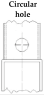 |  |  | Type of Failure | |||||
|---|---|---|---|---|---|---|---|---|---|---|
| KB1 | 85.6 | 88.8 | 84.7 | 87.8 | 84.3 | 88.1 | 82.5 | 86.8 | BF | |
| KB2 | 125.1 | 125.7 | 124.8 | 126.2 | 123.9 | 124.9 | 121.9 | 123.5 | BF | |
| KC3 | 100.9 | 108.9 | 100.8 | 107.6 | 96.7 | 107.3 | 96.9 | 106.0 | CF | |
| KB4 | 75.5 | 90.6 | 75.3 | 89.8 | 74.4 | 89.5 | 72.8 | 88.7 | BF | |
| KB5 | 94.5 | 107.0 | 92.3 | 105.9 | 92.6 | 106.5 | 91.5 | 105.2 | BF | |
| KC6 | 105.2 | 142.0 | 103.4 | 141.7 | 102.5 | 140.6 | 101.3 | 138.6 | CF | |
| KC7 | 112.7 | 183.5 | 111.7 | 184.1 | 109.3 | 181.7 | 109.2 | 178.8 | CF | |
| KC8 | 74.1 | 95.5 | 74.4 | 94.4 | 72.6 | 94.4 | 71.5 | 93.8 | CF | |
| NC9 | 42.8 | 99.9 | 42.7 | 99.5 | 41.4 | 96.7 | 42.0 | 98.2 | CF | |
| NP10 | 67.0 | 99.8 | 65.7 | 100.1 | 64.2 | 98.0 | 64.1 | 98.8 | PS | |
| NP11 | 91.2 | 102.6 | 91.1 | 102.7 | 87.2 | 101.3 | 87.7 | 101.7 | PS | |
| Type of vent hole | ||||||
|---|---|---|---|---|---|---|
| Circular | Semi-circular | V-notched | ||||
| 3%b0 | Max. load | 3%b0 | Max. load | 3%b0 | Max. load | |
| Mean of deviation [%] | −0.78 | −0.45 | −2.25 | −1.30 | −3.43 | −1.91 |
| Maximum deviation [%] | −2.34 | −1.2 | −4.23 | −3.23 | −4.31 | −2.69 |
© 2019 by the authors. Licensee MDPI, Basel, Switzerland. This article is an open access article distributed under the terms and conditions of the Creative Commons Attribution (CC BY) license (http://creativecommons.org/licenses/by/4.0/).
Share and Cite
Serrano, M.A.; López-Colina, C.; Gayarre, F.L.; Wilkinson, T.; Suárez, J. The Resistance of Welded Joints of Galvanized RHS Trusses with Different Vent Hole Geometries. Appl. Sci. 2019, 9, 1553. https://doi.org/10.3390/app9081553
Serrano MA, López-Colina C, Gayarre FL, Wilkinson T, Suárez J. The Resistance of Welded Joints of Galvanized RHS Trusses with Different Vent Hole Geometries. Applied Sciences. 2019; 9(8):1553. https://doi.org/10.3390/app9081553
Chicago/Turabian StyleSerrano, Miguel A., Carlos López-Colina, Fernando L. Gayarre, Tim Wilkinson, and Jesús Suárez. 2019. "The Resistance of Welded Joints of Galvanized RHS Trusses with Different Vent Hole Geometries" Applied Sciences 9, no. 8: 1553. https://doi.org/10.3390/app9081553
APA StyleSerrano, M. A., López-Colina, C., Gayarre, F. L., Wilkinson, T., & Suárez, J. (2019). The Resistance of Welded Joints of Galvanized RHS Trusses with Different Vent Hole Geometries. Applied Sciences, 9(8), 1553. https://doi.org/10.3390/app9081553