Article

The Exoskeleton Balance Assistance Control Strategy Based on Single Step Balance Assessment

1
State Key Laboratory of Robotics and System, Harbin Institute of Technology (HIT), Harbin 150001, China
2
Shenzhen Academy of Aerospace Technology, Shenzhen 518057, China
3
Department of Advanced Robotics, Istituto Italiano di Tecnologia, Via Morego 30, 16163 Genova, Italy
*
Authors to whom correspondence should be addressed.
Appl. Sci. 2019, 9(5), 884; https://doi.org/10.3390/app9050884
Submission received: 25 January 2019 / Revised: 19 February 2019 / Accepted: 26 February 2019 / Published: 1 March 2019
(This article belongs to the Special Issue Human Friendly Robotics)

Abstract

:
A novel balance assistance control strategy of a hip exoskeleton robot was proposed in this paper. The organic fusion of the human balance assessment and the exoskeleton balance assistance control strategy are the assurance of balance recovery. However, currently there are few human balance assessment methods that are suitable for detecting balance loss during standing and walking, and very little research has focused on exoskeleton balance recovery control. In this paper, a single step balance assessment method was proposed first, and then based on this method an "assist-as-needed" balance assistance control strategy was established. Finally, the exoskeleton balance assistance control experiment was carried out. The experiment results verified the effectiveness of the single balance assessment method and the active balance assistance control strategy.

1. Introduction

Falls are one of the main causes of disability and death of elderly people. The balance ability declines with age and the chance of falls is greatly increased [1]. Traditional walking aids, such as canes or crutches, play an important role in the life of elderly people. Although canes and crutches can prevent falls to some degree, they are unable to offer active assist to the user. Essentially, canes and crutches can only enlarge the stability region of walking, but the key for balance recovery still relies on the cognitive and physical status of the user. Hence, as the muscle strength and reaction speed of elderly people decline with age [2], it is still a big challenge for elderly people using canes and crutches to regain balance when they suffer from an unexpected perturbation. In fact, elderly people can still generate a strategy for balance recovery, but, unfortunately, their limbs are not strong enough and cannot be moved fast and to prevent falls [3]. Therefore, a new kind of walking aid that can provide active assist for human limbs is required.
Exoskeleton technology is a promising solution for active balance assistance. For the last two decades, exoskeletons have been widely studied and have been successfully applied in load carrying [4,5], rehabilitation of paralyzed patients [6,7], and walking assistance [8]. Recently some exoskeleton research has shown the potential of active balance assistance [1,9,10]. Giovacchini F et al design a light-weight active orthosis for hip movement assistance [11]. They test the performance of the device on a healthy subject. The results showed that the subject could walk with the device without being hindered and while he received a smooth assistive flexion-extension torque profile on both hip articulations. This research shows the potential of the exoskeleton in balance assistance for humans.
Currently, the man–machine interaction performance is one of the key points for the application of exoskeletons. For the user who still has autonomous walking ability, the exoskeleton should follow the motion intention of the user, and "assist-as-need" have turned out to be a more effective method for balance assistance [12]. "Assist-as-need" means, for balance assistance purposes, an exoskeleton provides assistance only when the upcoming balance loss is detected. Therefore, a real-time balance assessment method is needed to evaluate the degree of balance and detect the moment of balance loss. When balance loss is detected, the exoskeleton will provide appropriate assistance power according to the degree of balance and the current motion state of the user. Hence, organic fusion of the human balance assessment method and the exoskeleton balance recovery control are the assurance of balance recovery.
Many studies have focused on fall detection and have some achievements in the detection method based on visual detection and wearable sensors [13]. However, fall detection is different from balance loss detection, the detection purpose and detection time are different from each other. Fall detection aims at judging whether the human is falling down and when it happens a warning signal is sent out for rescue. Conversely, balance loss detection aims at judging whether a human has a trend of falls and when a trend is detected a signal will be sent out to the assistance devices to help the user prevent falls. Some balance loss detection methods based on zero moment point (ZMP) [14], capture point (CP) [15], and adaptive oscillators [16] were proposed. There are some limitations in these studies. ZMP method is not suitable for walking on the uneven ground. CP method is a powerful tool to assess balance degree during standing, but is not enough to assess balance degree during dynamic walking. Adaptive oscillators are only suitable for periodic gait. Current balance assessment methods ignore the position and velocity of the swing foot. Because the swing foot is the future support foot, the position and velocity of the swing foot are important for balance recovery.
Nowadays, most research on exoskeleton control focuses on walking assistance rather than balance assistance. In recent years, there are more and more studies focused on how to assist the user when they lose balance. Current balance assistance control strategies can be classified into three categories including adaptive variable stiffness control [17,18], joint trajectory tracking control [19,20], and joint torque control [1,21]. Joint trajectory tracking control is more suitable for gait rehabilitation rather than balance assistance, because the planned trajectory may conflict with human intention and increase the risk of falls. Current adaptive variable stiffness is only used for balance recovery during standing. Current joint torque control is an open-loop control that only provides assistance torque with a certain time when users lose balance, but the amplitude and action time of assist torque still need to be optimized.
The main contributions of this paper are proposing a real-time balance assessment method that is suitable for both standing and walking, and then establishing an active balance assist control strategy that is based on the "assist-as-needed" principle that exoskeletons only provide assist power when balance loss is detected. The assist torque profile is calculated according to the degree of balance and fuzzy logical control (FLC).
This paper is organized as follows: Section 2 proposes the real-time balance assessment method. Section 3 proposes the active balance assist control strategy. Section 4 makes a detailed analysis of the balance control experiments. Section 5 concludes the paper and suggests the future work.

2. Single Step Balance Assessment Method

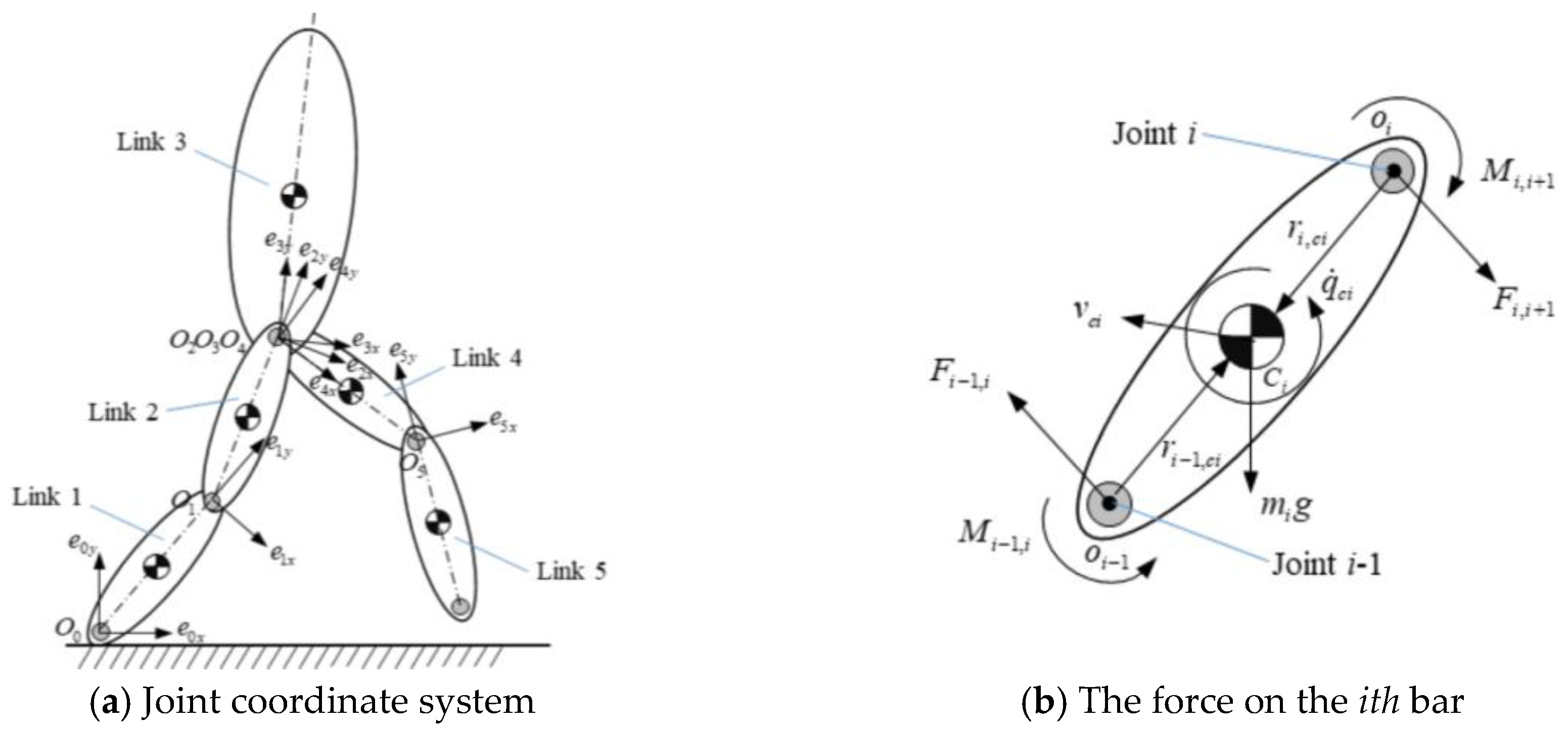
2.1. The Concept of Single Step Balance

In this paper, single step balance is defined as a state in which a human is able to regain balance in one step. It is important for humans, especially for elderly and disabled people, to regain balance within a minimum number of steps when suffering from an unexpected disturbance. To quantitatively evaluate whether a human is in a single step balance state, the CP concept [14] is utilized in this paper.
x C P = x + x ˙ l / g
where x C P is the position of CP, l is the distance between the center of mass (CoM) of the human and ankle, g is gravitational acceleration. On the basis of the CP concept, as shown in Figure 1, a single step balance state is defined as a state that when the swing foot is touching the ground and the CP is within the base of support (BoS). Conversely, if CP is outside of the BoS when the swing foot touches down, the human is in a single step unbalance state.
Based on this definition of single step balance and (1), it is obvious that the degree of single step balance is determined by the state of CoM ( [ x , x ˙ ] ). To investigate the relationship between a single step balance state and the velocity of CoM, 30 groups of “walk-stop” experiments for every 5 healthy young male adults (Mean age: 23.5 (1.3), mean weight: 58.7 (5.1) kg, mean trunk length: 0.432 (0.025) m, mean leg length: 0.815 (0.05) m, mean length between ankle and toe: 0.168 (0.06) m) were carried out. All subjects gave their informed consent before participating in the experiment. The experiment was approved by the Harbin Institute of Technology ethical committee. The kinematics data of the human walking are measured by Raptor-4 Digital Realtime System of Motion Analysis corp. 12 Raptor-4 digital cameras send the trails of markers on the human body to the Cortex software for data acquisition at 120 Hz. A 22-markers Helen-Hayes model was adopted in this experiment. During the “walk-stop” experiment, all subjects were required to walk at a given speed and tried to stop in one step when hearing the unexpected stopping command. If the subject can stop walking in only one step, the subject is considered as in the single step balance state, otherwise the subject is in the single step unbalance state. The results of “walk-stop” experiment are shown in Table 1.
The experiment results in Table 1 show that the success rates of stopping walking in one step at low and medium walking speed are 100% and 99%, respectively. However, the success rate drops to 2.7% when walking speed is high. Therefore, the human is able to keep single step balance at low and medium walking speed, and is almost in a single step unbalance state at a high walking speed.
To investigate the relationship between the swing foot and CP, another 10 groups of experiments were carried out. Each subject walked at three different speeds (low, medium, and high) and suffered from an unexpected forward disturbance during walking. Figure 2 shows the results of one subject (Age: 24, weight: 55 kg, leg length: 0.802 m). As shown in Figure 2, the time of the swing foot touching down before disturbance is tA, and the time of the swing foot touching down after disturbance is tB. The distance between CP and the ankle of the swing foot is noted as dSC, and the average value of dSC in tA and tB are shown in Table 1. The average distance between the toe and ankle is lf = 0.168 m, and the distance between dSC and lf determines whether the human is in single step balance. The degree of balance can be calculated by the distance between dSC and lf. If dSC > lf, the human is in a single step unbalance state, and conversely if dSClf, the human is in a single step balance state. Comparing dSC in Table 1 with lf, it is obvious that dSC (tA) is smaller than lf at low and medium walking speed and larger than lf at high walking speed. This result suggests that, at low and medium walking speed, the swing foot can catch up with CP when touching down, but at high walking speed, the swing foot is unable to catch up with CP when touching down. As shown in Table 1, dSC (tB) is always larger than lf no matter when a human walks at low, medium, or high speed. That means the swing foot is unable to catch up with CP when a human suffers from a disturbance.
From the above experiment results, we conclude that a human is in a single step balance state if the swing foot can catch up with CP when the swing foot is touching down, and if the swing foot is unable to catch up with CP when it is touching down, a human is in a single step unbalance state which means the human will lose balance. The degree of single step balance can be calculated by the distance between dSC and lf. Therefore, the key to judging whether a human will lose balance is to judge whether the swing foot can catch up with CP before or when the swing foot is touching down. Hence, the future position of the swing foot and CP need to be predicted first.

2.2. Method for Single Step Balance Assessment

To predict the position of the swing foot, an inverted pendulum model with a finite sized foot [22] and an ankle torque model are utilized in this paper. The inverted pendulum model with a finite sized foot is given by (2), and the ankle torque model is given by (3).
x ¨ = g l ( x x a n k l e ) τ a n k l e m l
where x is the position of CoM, x ¨ is the acceleration of CoM, x a n k l e is the ankle position of the support foot, τ a n k l e is the ankle torque of the support foot, m is the total mass of the human body and l is the leg length.
τ a n k l e = { τ 1 sin π x x a n k l e if   x x a n k l e 0 τ 2 sin π 2 L 2 ( x x a n k l e ) if   x x a n k l e > 0
where τ 1 and τ 2 are the peak torque of flexor and extensor, respectively. L 2 is the average stride length of quasi-period walking.
Previous research [23] has proposed the relationship between ankle torque and gait cycle during quasi-period walking. As shown in Figure 3a, the relationship between the position of CoM and ankle torque can be calculated according to the velocity of CoM. To establish the torque model, the ankle torque profile shown in Figure 3a can be described by the sine curve function given by (3), and the fitting error is below 10% which is precise enough to predict the ankle torque of the support foot during quasi-periodic walking.
According to model (2) and (3), the state of CoM ([x, x ˙ ]) can be predicted. In order to verify the feasibility of prediction, the predicted state of CoM are compared with the experimental data obtained under the same experiment setup. The prediction results and experiment data are shown in Figure 4.
In Figure 4, it is obvious that the predicted positions of CoM are close to the experimental value (Mean error: 0.03(0.02) m), and the maximum error between predicted velocity and real velocity of CoM is within 10%. Hence, the model (2) and (3) can be used to predict the state of CoM and the position of CP can be predicted simultaneously.
The prediction of the swing foot position is based on the law of the swing foot. Previous research has shown that the swing foot accelerates at the beginning of the swing phase and decelerates at the end of the swing phase [24]. The measured acceleration of the swing foot is shown in Figure 5a, from which it can be seen that the fluctuation of the swing foot acceleration and deceleration are small. Hence within the allowable error, the motion of the swing foot can be considered as a uniformly accelerated motion and a uniformly decelerated motion. The equivalent acceleration of the swing foot is shown in Figure 5b, and based on this equivalent acceleration and the remaining time for the swing foot chasing CP, the swing foot position can be predicted. The equivalent acceleration aa and ad can be obtained from the statistic data of human walking.
Due to biomechanical constraints and personal walking habits, the time for the swing foot chasing CP is limited. As shown in Figure 6, the angle between the support leg and the vertical line when the swing foot is touching down is noted as θ f or θ b , here θ f is defined as the forward angle and θ b is defined as the backward angle. The time of reaching θ f or θ b are denoted as t f and t b , respectively. According to (2), t f and t b can be calculated. The time the swing foot catches up with CP before touching down is denoted as t g , and x ( t f ) x ( t g ) or x ( t g ) x ( t b ) is denoted as the degree of single balance. If the swing foot is unable to catch up with CP before or when touching down, the degree of single balance M is denoted as x s w i n g ( t f ) x C P ( t f ) or x C P ( t b ) x s w i n g ( t b ) , here x s w i n g ( t f ) and x s w i n g ( t b ) are the position of the swing foot at the time of t f and t b , respectively. M can be given by (4), where t θ is t f and t b .
M = { sgn ( x ˙ ) ( x ( t θ ) x ( t g ) ) single step balance sgn ( x ˙ ) ( x s w i n g ( t θ ) x C P ( t θ ) ) single step unbalance

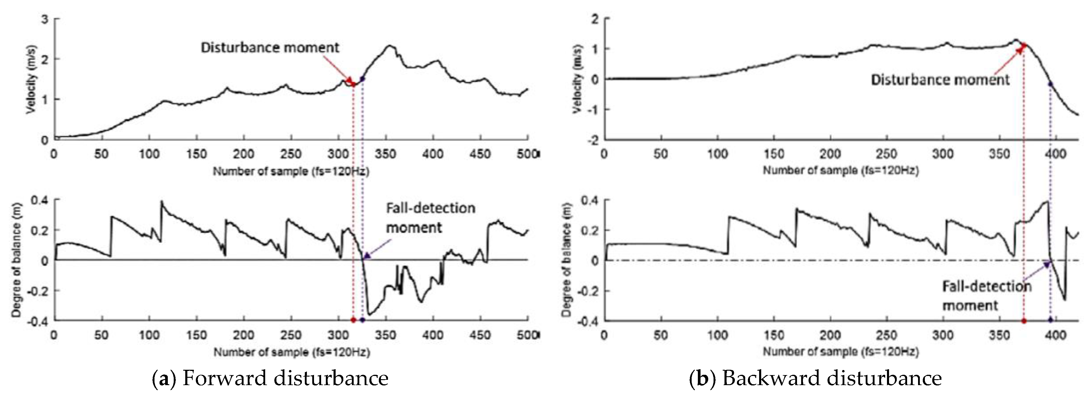
2.3. Single Step Balance Assesment Experiment

To verify whether the proposed single step balance assessment method can rapidly detect the balance loss when a human suffers from disturbance during walking, the forward disturbed walking and backward disturbed walking experiments are carried out. The kinematics data of human walking are measured by Raptor-4 Digital Realtime System of Motion Analysis corp. 12 Raptor-4 digital cameras send the trails of markers on the human body to the Cortex software for data acquisition at 120 Hz. A 22-markers Helen-Hayes model was adopted in this experiment. The results between subjects showed good consistency. Thus, one of the experiment results of forward disturbed walking and backward disturbed walking is shown in Figure 7a,b, respectively.
It can be seen from Figure 7a that the degree of single step balance is always positive before disturbance happens, and this means a human is in a single step balance state before disturbance applied. The degree of single step balance declines sharply and becomes negative after 50 ms of disturbance. Hence, the proposed single step balance assessment method successfully and quickly detects the trend of balance loss. In this experiment, the time required to detect the balance loss is about 50 ms.
Similarly, as shown in Figure 7b, the degree of single step balance becomes negative after about 150 ms of disturbance. Compared with the forward disturbance experiment, it is obvious that the time required to detect the balance loss is significantly increased. The reason for this phenomenon is that the human is still in a single step balance state for a period of time after the disturbance, and the human remains in a single step unbalance state until the disturbance acts for a long enough time to change the velocity direction of CoM. Hence, the proposed single balance assessment method is also suitable for evaluating the degree of single step balance when a human suffers from a backward disturbance.

3. Exoskeleton Balance Assistance Control Strategy

The exoskeleton balance assistance control strategy based on single step balance assessment is shown in Figure 8. The control framework mainly consists of three parts: human motion state estimation, human single step balance assessment, and active balance assistance control. Based on the human kinematics and the sensor data from the inertial measurement unit (IMU) and foot pressure insoles, the state of CoM ( [ x ( t ) , x ˙ ( t ) ] ) and the state of the swing foot ( [ x s w i n g ( t ) , x ˙ s w i n g ( t ) ] ) are estimated. Grounding in the state of CoM and the swing foot, the single step balance assessment method evaluates the single step balance degree of the current posture of a human and detects incipient falls. Finally, the fuzzy inference system is used to establish the relationship between the single step balance degree M and the assistant coefficient ( α G , α C , α I ) , and then the assistant torques are calculated based on the human dynamics model and the assistant coefficient.

3.1. Assistant Torque

To generate the assistant torque, the human hip joint torque is calculated first. Based on the Newton–Euler method and the joint coordinate system shown in Figure 9a, the swing leg hip joint torque can be given by (5). The hip joint torque is consist of gravity term ( τ 4 G ), Coriolis term ( τ 4 C ) and inertial term ( τ 4 I ).
{ τ 4 = τ 4 I + τ 4 C + τ 4 G τ 4 I = I 4 w ˙ 4 + I 5 w ˙ 5 τ 4 C = m 4 r 3 , c 4 × v ˙ 4 + m 5 ( r 3 , c 4 + r 4 , c 4 r 4 , c 5 ) × v ˙ 5 τ 4 G = m 4 r 3 , c 4 × g + m 5 ( r 3 , c 4 + r 4 , c 4 r 4 , c 5 ) × g
To generate the assistant torque, the human hip joint torque is calculated first. Based on the Newton–Eule
T e x o = α G τ G + α C τ G + α I τ I
where I 4 and I 5 are the moment of inertia relative to the CoM of the swing leg thigh and shank, respectively. m 4 and m 5 are the mass of the swing leg thigh and shank, respectively. w ˙ 4 and w ˙ 5 are the angular velocity of the swing leg thigh and shank, respectively. v ˙ 4 and v ˙ 5 are the CoM acceleration of the swing leg thigh and shank, respectively. r 3 , c 4 is the radius vector pointing from joint 3 to the center of bar 4, and the definition of r 4 , c 4 and r 4 , c 5 are similar to r 3 , c 4 . Because the mass of the exoskeleton is distributed especially onto the trunk, the mass of the exoskeleton has been added to the mass of trunk.
Previous research has shown that an exoskeleton can achieve a good performance of assistance when the gravity term, Coriolis term, and inertial term of hip joint torque are compensated by the exoskeleton independently [25]. Hence, in this paper, the assistant hip joint torque ( T e x o ) generated by the exoskeleton compensates the gravity term, Coriolis term, and inertial term simultaneously. The assistant coefficients for gravity term, Coriolis term, and inertial term are denoted as α G , α C , and α I . The relationship between the assistant coefficient and the degree of single step balance is established by the fuzzy inference system.

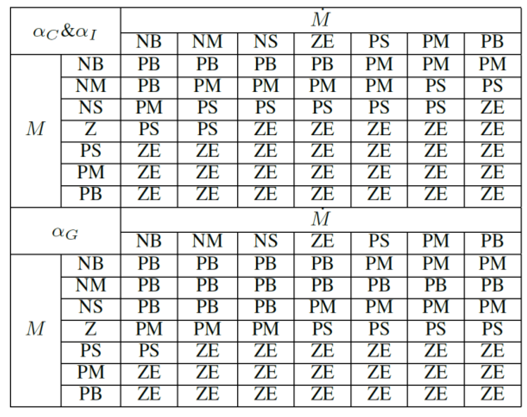
3.2. Assistant Coefficient Generated by FLC

FLC is a common way to establish a nonlinear relationship. In this paper, the relationship between the assistant coefficient and the degree of single step balance is established by a two-dimensional FLC. The inputs of two-dimensional FLC are the degree of single step balance (M) and its rate ( M ˙ ) as shown in Figure 10, and the outputs of it are the assistant coefficient ( α G , α C and α I ) as shown in Figure 11.
Input fuzzy partition with seven terms: NB, negative big; NM, negative medium; NS, negative small; Z, zero; PS, positive small; PM, positive medium; and PB, positive big. Output fuzzy partition with four terms: ZE, zero; PS, positive small; PM, positive medium; and PB, positive big. The universe of discourse of M and M ˙ are [−0.6 m, 0.6 m] and [−6 m/s, 6 m/s], respectively. Previous research suggested that in order to ensure the stability of a man–machine system the maximum assistant coefficient for the inertial term is 0.47 [25]; hence the universe of discourse of α I is chosen as [0, 0.3]. To ensure the comfort the universe of discourse of α G and α C are set as [0, 0.6].
The fuzzy rules of FLC are established as follow. If M > 0, the assistant coefficient equals to zero, because the human is in the single step balance state. If M ≤ 0, the assistant coefficient should be generated by the FLC. Because the properties of gravity term, Coriolis term, and inertial term are different from each other, the fuzzy rules for each term should be different. The inertial force and Coriolis force will increase with the walking speed, hence M ˙ has a greater effect on the Coriolis term and inertial term. The gravity term is only influenced by the posture of the human body; hence M has a greater effect on gravity term. Based on the above analysis, the fuzzy rules of α G , α C , and α I are given by Figure 12.

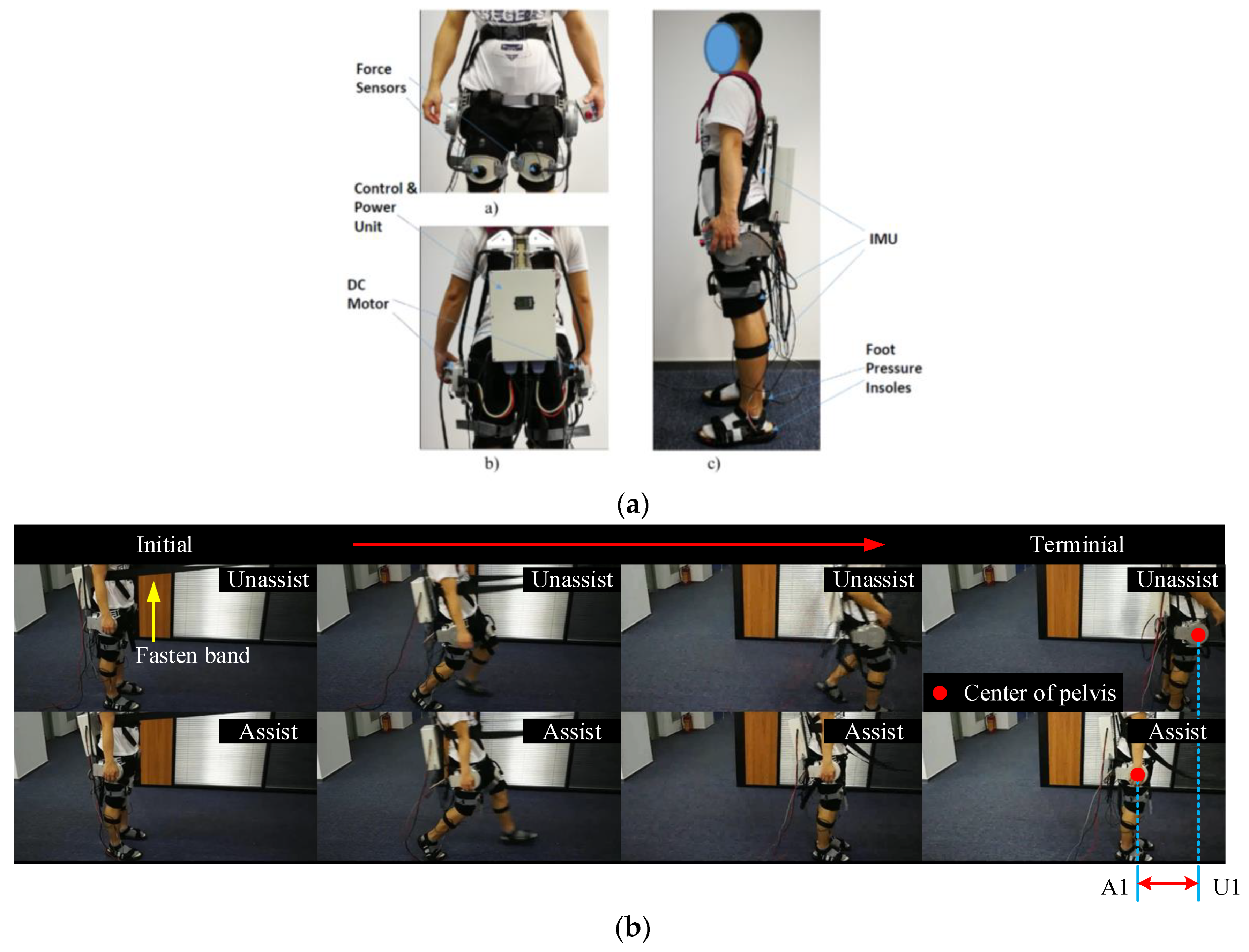
4. Exoskeleton Balance Assistance Control Experiment

The hip assist exoskeleton (HAE) developed by our team is shown in Figure 13a. HAE has two motor-driven joints that rotate in flexion/extension. The exoskeleton actuator system contains a 24 V brushless DC motor and a planetary gearbox with 8:1 reduction rate. The rated torque of the exoskeleton actuator system is 40Nm. The total mass of HAE is about 10.8 kg. HAE includes two force sensor to detect the interaction force between the exoskeleton and human thigh, five IMUs that are worn by the user are used for human posture detection and CoM state estimation, and two pressure insoles are used for ground contact detection.
The experiment included forward/backward pulling by a fasten band, Figure 13b is the experiment environment of forward pulling. Figure 13c is the experiment environment of backward pulling.
To verify the effectiveness of the proposed balance assistance control strategy, forward and backward disturbance experiments are carried out. Three subjects wearing HAE and performing four experiments including standing forward pull, standing backward pull, walking forward pull, and walking backward pull. The disturbance force pulse was generated by a pneumatic system and the maximum disturbing force was set to be 120 N and the duration time of disturbance force pulse was set to be 0.5 s. In these experiments, the exoskeleton is working in two control modes: active balance assist mode (ASS) and transparent mode (TRA). All subjects gave their informed consent before participating in the study. The results between subjects have shown great consistency. The experiment was approved by the Harbin Institute of Technology ethical committee.

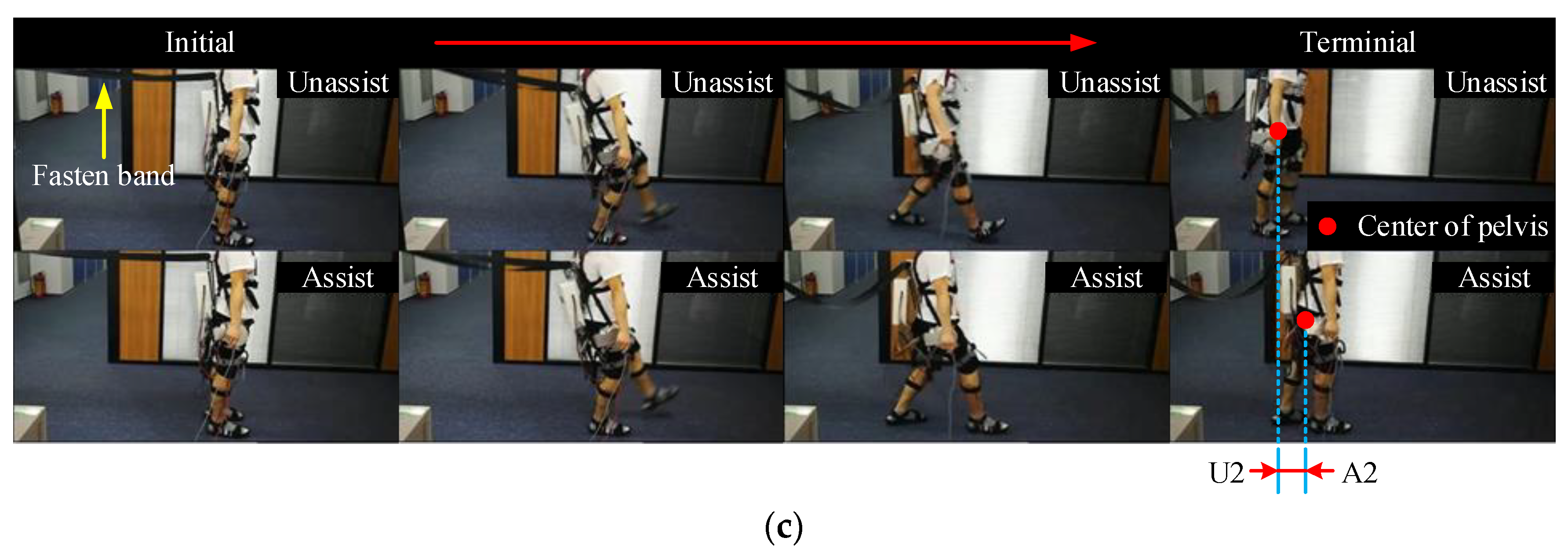
4.1. Analysis of the Degree of Single Balance

As shown in Figure 14, the degree of single step balance declines sharply when a human suffers from a disturbance. The balance loss is successfully detected by the exoskeleton, the mean detection time of forward and backward balance loss are 90 ms and 190 ms, respectively. Because the time from stable walking to falling is about 500~700 ms [1], humans still have enough time to regain balance after the balance loss is detected. Furthermore, it is obvious that when the exoskeleton works in ASS mode the degree of single step balance can increase faster, and that means with the assistance of an exoskeleton a human can regain single step balance earlier.

4.2. Analysis of the Hip Joint Angle

Humans tend to lose forward balance when they suffer from a forward disturbance force. As shown in Figure 15a,c, the hip joint is moving faster in ASS mode than in TRA mode, and the time to reach the maximum position is reduced about 0.1~0.15 s. This phenomenon indicates that the speed of the human limb becomes faster when an exoskeleton actively assists the human to regain balance. The same phenomenon can be observed when a human suffers from a backward disturbing force. As shown in Figure 15b,d, the human hip angle is decreased faster in ASS mode than in TRA mode, and that means the swing foot is moving backward at a higher speed. Hence, the swing foot can catch up with CP earlier. These results show that the active balance assist controller proposed in this paper is able to increase the speed of the swing foot and promote balance recovery.

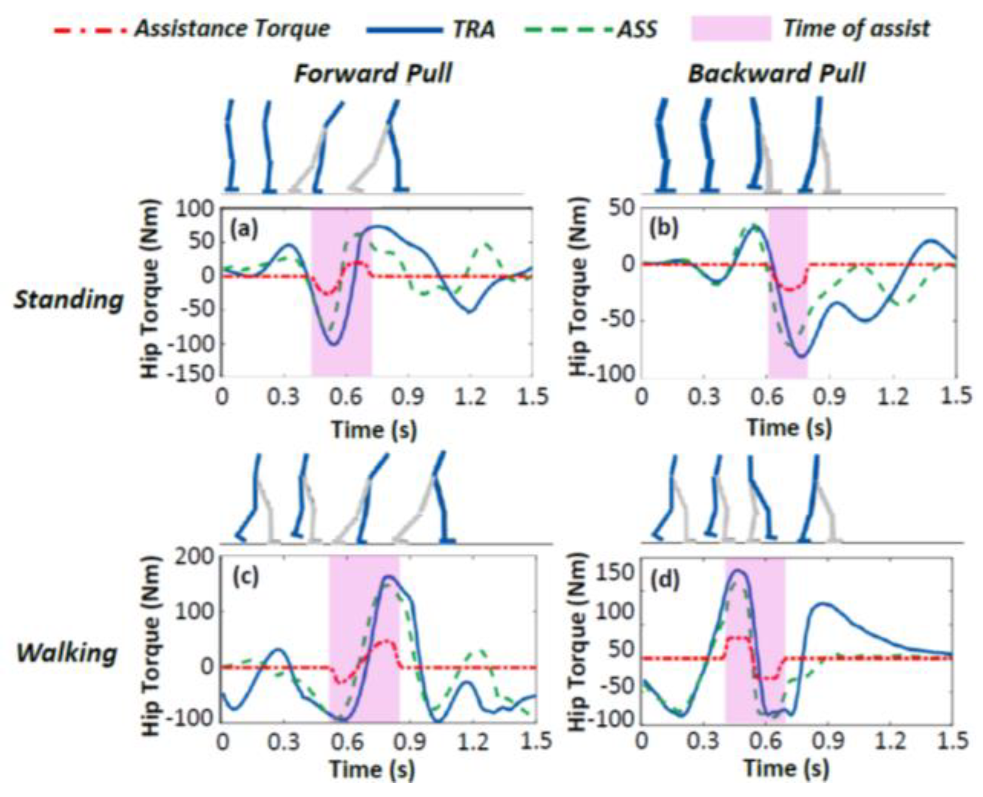
4.3. Analysis of the Hip Joint Torque

As shown in Figure 16, the direction of assistance torque coincides with the direction of hip joint torque, that means the assistance torque generated by the exoskeleton complies with the human intention. Comparing the hip joint torque when the exoskeleton works in ASS and TRA mode, we found that the maximum hip joint torque is significantly reduced about 15~20 Nm. For this reason, humans can move their legs at a higher speed with the assistance of an exoskeleton, thereby improving the ability to regain balance.

5. Conclusions

A novel active balance assistance control strategy based on single step balance assessment is proposed in this paper. The human forward and backward disturbance experiments show that the balance loss can be detected quickly, and the single step balance degree can be mapped to the assistance torque by FLC and human dynamics model. The assistance torque generated by the exoskeleton coincides with the direction of human hip joint torque, and, therefore, with the assistance of an exoskeleton, humans can move their legs faster. Faster leg movements help humans respond more quickly when they are about to fall and to regain single step balance earlier.
As a proof of concept, this paper shows the potential for a hip exoskeleton to help a human regain single step balance after forward or backward disturbance. However, future research is still facing challenges. The single step balance assessment method needs to be optimized to further reduce the detection time of balance loss. And to further verify the effectiveness of the proposed balance assistance controller, experiments on elderly people or amputees are needed in future work.

Author Contributions

W.S. and S.Q. conceived the method and wrote the paper; F.Z. and W.G. helped to modify it; S.Q. performed the experiments and analyzed the data; F.C., F.Z. and X.W. contributed theoretical justification and reference materials. All authors have read and approved the final manuscript.

Funding

This research was funded by the National Natural Science Foundation of China (No.61473015, JCYJ20160425150757025, No. U1713222, and No.61773139), and Shenzhen Peacock Plan (KQTD2016112515134654).

Conflicts of Interest

The authors declare no conflict of interest.

References

  1. Monaco, V.; Tropea, P.; Aprigliano, F.; Martelli, D.; Parri, A.; Cortese, M.; Molino-Lova, R.; Vitiello, N.; Micera, S. An ecologically-controlled exoskeleton can improve balance recovery after slippage. Sci. Rep. 2017, 7, 46721. [Google Scholar] [CrossRef] [PubMed]
  2. Pavol, M.J.; Owings, T.M.; Foley, K.T.; Grabiner, M.D. Influence of Lower Extremity Strength of Healthy Older Adults on the Outcome of an Induced Trip. J. Am. Geriatr. Soc. 2002, 50, 256–262. [Google Scholar] [CrossRef] [PubMed] [Green Version]
  3. Agrawal, Y.; Carey, J.P.; Della Santina, C.C.; Schubert, M.C.; Minor, L.B. Diabetes, vestibular dysfunction, and falls: Analyses from the National Health and Nutrition Examination Survey. Otol. Neurotol. Off. Publ. Am. Otol. Soc. Am. Neurotol. Soc. Eur. Acad. Otol. Neurotol. 2010, 31, 1445–1450. [Google Scholar] [CrossRef] [PubMed]
  4. Suzuki, K.; Mito, G.; Kawamoto, H.; Hasegawa, Y.; Sankai, Y. Intention-based walking support for paraplegia patients with Robot Suit HAL. Adv. Robot. 2007, 21, 1441–1469. [Google Scholar]
  5. Kazerooni, H.; Steger, R.; Huang, L. Hybrid Control of the Berkeley Lower Extremity Exoskeleton (BLEEX). IEEE/ASME Trans. Mechatron. 2006, 11, 128–138. [Google Scholar] [CrossRef]
  6. Raab, K.; Krakow, K.; Tripp, F.; Jung, M. Effects of training with the ReWalk exoskeleton on quality of life in incomplete spinal cord injury: A single case study. Spinal Cord 2016, 2, 15025. [Google Scholar] [CrossRef] [PubMed]
  7. Buesing, C.; Fisch, G.; O’Donnell, M.; Shahidi, I.; Thomas, L.; Mummidisetty, C.K.; Williams, K.J.; Takahashi, H.; Rymer, W.Z.; Jayaraman, A. Effects of a wearable exoskeleton stride management assist system (SMA?) on spatiotemporal gait characteristics in individuals after stroke: A randomized controlled trial. J. Neuroeng. Rehabil. 2015, 12, 69. [Google Scholar] [CrossRef] [PubMed]
  8. Parri, A.; Yan, T.; Giovacchini, F.; Cortese, M.; Muscolo, M.; Fantozzi, M.; Lova, R.M.; Vitiello, N. A Portable Active Pelvis Orthosis for Ambulatory Movement Assistance. In Proceedings of the Wearable Robotics: Challenges and Trends; Springer International Publishing: Cham, Switzerland, 2017. [Google Scholar]
  9. Wang, S.; Wang, L.; Meijneke, C.; Van Asseldonk, E.; Hoellinger, T.; Cheron, G.; Ivanenko, Y.; La Scaleia, V.; Sylos-Labini, F.; Molinari, M.; et al. Design and control of the MINDWALKER exoskeleton. IEEE Trans. Neural Syst. Rehabil. Eng. 2015, 23, 277–286. [Google Scholar] [CrossRef] [PubMed]
  10. Zhang, T.; Tran, M.; Huang, H. Design and Experimental Verification of Hip Exoskeleton with Balance Capacities for Walking Assistance. IEEE/ASME Trans. Mechatron. 2018, 23, 274–285. [Google Scholar] [CrossRef]
  11. Giovacchini, F.; Vannetti, F.; Fantozzi, M.; Cempini, M.; Cortese, M.; Parri, A.; Yan, T.; Lefeber, D.; Vitiello, N. A light-weight active orthosis for hip movement assistance. Robot. Auton. Syst. 2015, 73, 123–134. [Google Scholar] [CrossRef]
  12. Li, D.; Vallery, H. Gyroscopic assistance for human balance. In Proceedings of the 2012 12th IEEE International Workshop on Advanced Motion Control (AMC), Sarajevo, Bosnia-Herzegovina, 25–27 March 2012; pp. 1–6. [Google Scholar]
  13. El-Bendary, N.; Tan, Q.; Pivot, F.C.; Lam, A. Fall detection and prevention for the elderly: A review of trends and challenges. Int. J. Smart Sens. Intell. Syst. 2013, 6, 1230–1266. [Google Scholar] [CrossRef]
  14. Aphiratsakun, N.; Parnichkun, M. Balancing Control of AIT Leg Exoskeleton Using ZMP based FLC. Int. J. Adv. Robot. Syst. 2010, 6, 319–328. [Google Scholar] [CrossRef]
  15. Pratt, J.; Carff, J.; Drakunov, S.; Goswami, A. Capture Point: A Step toward Humanoid Push Recovery. In Proceedings of the 2006 6th IEEE-RAS International Conference on Humanoid Robots, Genova, Italy, 4–6 December 2006; pp. 200–207. [Google Scholar]
  16. Tropea, P.; Vitiello, N.; Martelli, D.; Aprigliano, F.; Micera, S.; Monaco, V. Detecting Slipping-Like Perturbations by Using Adaptive Oscillators. Ann. Biomed. Eng. 2014, 43, 1–11. [Google Scholar] [CrossRef] [PubMed]
  17. Rajasekaran, V.; Aranda, J.; Casals, A.; Pons, J.L. An adaptive control strategy for postural stability using a wearable robot. Robot. Auton. Syst. 2015, 73, 16–23. [Google Scholar] [CrossRef] [Green Version]
  18. Ugurlu, B.; Doppmann, C.; Hamaya, M.; Forni, P.; Teramae, T.; Noda, T.; Morimoto, J. Variable Ankle Stiffness Improves Balance Control: Experiments on a Bipedal Exoskeleton. IEEE/ASME Trans. Mechatron. 2016, 21, 79–87. [Google Scholar] [CrossRef]
  19. Huynh, V.; Bidard, C.; Chevallereau, C. Balance Control for an Active Leg Exoske-leton based on Human Balance Strategies. In International Workshop on Medical & Service Robots; Springer: Cham, Switzerland, 2016; pp. 197–211. [Google Scholar]
  20. Sergey, J.; Sergei, S.; Andrey, Y. Comparative analysis of global optimization-based controller tuning methods for an exoskeleton performing push recovery. In Proceedings of the 2016 20th International Conference on System Theory, Control and Computing (ICSTCC), Sinaia, Romania, 13–15 October 2016; pp. 107–112. [Google Scholar]
  21. Song, K.T.; Chien, Y.L. Development of an assistive torque generation system for a lower limb exoskeleton. In Proceedings of the 2016 International Conference on System Science and Engineering (ICSSE), Puli, Taiwan, 7–9 July 2016; pp. 1–4. [Google Scholar]
  22. Hof, A.L.; Gazendam, M.G.J.; Sinke, W.E. The condition for dynamic stability. J. Biomech. 2005, 38, 1–8. [Google Scholar] [CrossRef] [PubMed]
  23. Krishnaswamy, P.; Brown, E.N.; Herr, H.M. Human leg model predicts ankle muscle-tendon morphology, state, roles and energetics in walking. PLoS Comput. Biol. 2011, 7, e1001107. [Google Scholar] [CrossRef] [PubMed]
  24. Lee, W.H.; Mansour, J.M. Linear approximations for swing leg motion during gait. J. Biomech. Eng. 1984, 106, 137. [Google Scholar] [CrossRef] [PubMed]
  25. Aguirre-Ollinger, G.; Colgate, J.E.; Peshkin, M.A.; Goswami, A. Design of an active one-degree-of-freedom lower-limb exoskeleton with inertia compensation. Int. J. Robot. Res. 2011, 30, 486–499. [Google Scholar] [CrossRef]
Figure 1. Single step balance and unbalance state.
Applsci 09 00884 g001
Figure 2. Relationship of CP and the swing foot in different walking speed.
Applsci 09 00884 g002
Figure 3. The relationship between the position of the center of mass (CoM) and ankle torque.
Applsci 09 00884 g003
Figure 4. The predicted and real state of CoM.
Applsci 09 00884 g004
Figure 5. Acceleration of the swing foot during quasi-period gait.
Applsci 09 00884 g005
Figure 6. The angle between the support leg and the vertical direction.
Applsci 09 00884 g006
Figure 7. The degree of single step balance during forward walking.
Applsci 09 00884 g007
Figure 8. The balance assistance control framework.
Applsci 09 00884 g008
Figure 9. The five-bar human dynamic model.
Applsci 09 00884 g009
Figure 10. Membership functions of fuzzy logical control (FLC)-Input: (a) Language variable architecture of M; (b) Language variable architecture of M ˙ .
Applsci 09 00884 g010
Figure 11. Membership functions of FLC-Output: (a) Language variable architecture of α I ; (b) Language variable architecture of α G and α C .
Applsci 09 00884 g011
Figure 12. Fuzzy rules of assistant coefficients.
Applsci 09 00884 g012
Figure 13. Hip assist exoskeleton (HAE) for gait and balance assistance: (a) The sensors and actuators of the exoskeleton; (b) The experiment environment of forward pulling; (c) The experiment environment of backward pulling.
Applsci 09 00884 g013aApplsci 09 00884 g013b
Figure 14. The degree of single step balance: (a) Forward pull while standing; (b) Backward pull while standing; (c) Forward pull while walking; (d) Backward pull while walking.
Applsci 09 00884 g014
Figure 15. The hip joint angle: (a) Forward pull while standing; (b) Backward pull while standing; (c) Forward pull while walking; (d) Backward pull while walking.
Applsci 09 00884 g015
Figure 16. The hip joint torque: (a) Forward pull while standing; (b) Backward pull while standing; (c) Forward pull while walking; (d) Backward pull while walking.
Applsci 09 00884 g016
Table 1. The results of “walk-stop” experiment.
Walking SpeedAverage Groups d S C ( m )
SuccessFail d S C ( t A ) d S C ( t B )
Low (0.8 m/s)3000.1150.307
Medium (1.3 m/s)29.70.30.1240.401
High (1.8 m/s)0.829.20.2930.538

