Article

Phase Offset Tracking for Free Space Digital Coherent Optical Communication System

1
Key Laboratory of Optical Engineering, Chinese Academy of Sciences, Chengdu 610209, China
2
School of Information and Communication Engineering, University of Electronic Science and Technology of China, Chengdu 610054, China
3
Institute of Optics and Electronics, Chinese Academy of Sciences, Chengdu 610209, China
4
University of Chinese Academy of Sciences, Beijing 100049, China
*
Author to whom correspondence should be addressed.
Appl. Sci. 2019, 9(5), 836; https://doi.org/10.3390/app9050836
Submission received: 10 January 2019 / Revised: 16 February 2019 / Accepted: 22 February 2019 / Published: 26 February 2019
(This article belongs to the Special Issue Light Communication: Latest Advances and Prospects)

Abstract

:
The coherent receiving method can improve the sensitivity of an optical signal receiver for free space optical communication system effectively. To implement coherent receiving, the phase offset between the local laser in the receiver and the received optical signal through the atmosphere needs to be measured and estimated. The commonly used algorithm is the Viterbi-Viterbi phase offset estimation method (VVPE) and this method always produces great errors especially with low SNR (signal to noise ratio). To improve the estimation performance, we present a new method combing the VVPE with the Kalman filter (VVPE-KF) to estimate the phase offset. This method can lower the estimation error by no less than 60%, when the SNR is low. To verify the performance of this new method, the constant parameter channel and atmosphere turbulence channel are employed to evaluate the algorithm. The impact of the atmosphere turbulence intensity on the tracking error is discussed.

1. Introduction

In an optical wireless communication system, the received optical signal is always weak as a result of the geometric loss, atmospheric absorption, and misalignment loss. In addition, the inhomogeneities in pressure and temperature changes in the atmosphere causes turbulence resulting in the variations in refractive index. Thus, the optical signal arriving at the receiver fluctuates [1,2,3,4]. To improve the performance of the receiver, the coherent detection in the receiver can be employed. With the coherent detection method, the weak received signal is amplified after mixing with the local laser, by which the reliability of the receiver is enhanced [5,6,7,8]. In order to implement the coherent receiving, the phase offset and the frequency between the signal and the local laser need to be measured and estimated.
An obvious means to estimate the phase offset is to employ the optical phase lock loop (OPLL) [9,10]. However, the OPLL raises the cost and cannot compensate for the channel impairment adaptively. With the recent advances of high-speed analog-to-digital converter and high-performance digital signal processor, the receiver using digital signal processing (DSP) algorithm can implement the coherent receiving, eliminating the need for OPLL [11,12,13,14,15]. The Viterbi-Viterbi phase estimation (VVPE) algorithm is the most commonly used method to measure the phase offset, and it has been demonstrated to be effective for coherent receiver within a certain range of SNR [16,17]. Once the SNR is lower than this range, the performance of VVPE will be degraded severely by the noise and may not meet the system requirement. In this paper, a new algorithm combining VVPE with the Kalman filter is presented for satellite-to-ground downlink. With both constant parameter channel and atmosphere turbulence channel, this new method can reduce phase offset estimation error greatly with low SNR. When the SNR is under 10 dB, comparing the traditional VVPE, the error is lowered more than 60% by this new method. In addition, the performance of this new algorithm is less affected by the atmosphere turbulence than the traditional algorithm.

2. System Model

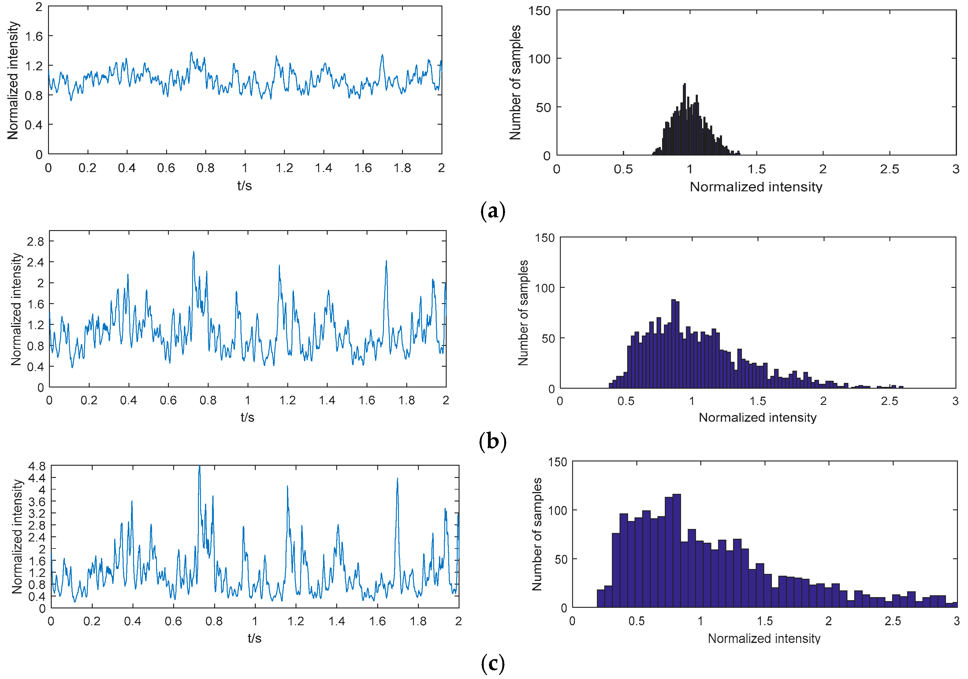
2.1. Atmosphere Channel Model
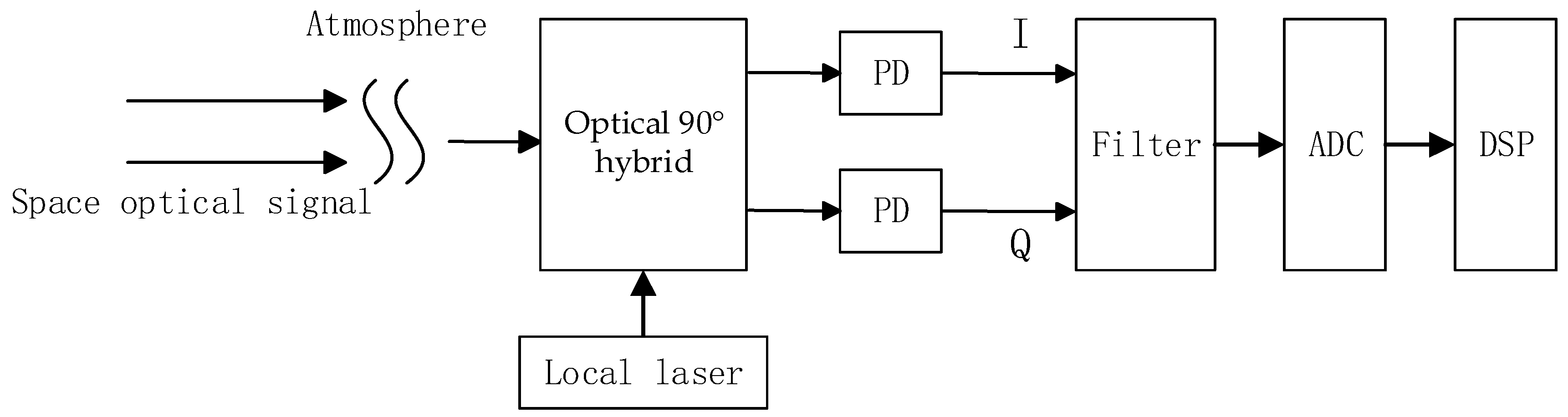
The optical signal through the atmosphere turbulence channel suffers from random fluctuations as a result of the distorted refractive index caused by time-varying temperatures and pressures. The probability density function (PDF) of the normalized optical irradiance I can be described by the log-normal model as [18]:
f ( I ) = 1 2 π σ l 2 1 I exp [ ( ln I + σ l 2 2 ) 2 2 σ l 2 ] ;   I 0
The key parameter σ l 2 of this PDF is the Rytov variance and for satellite-to-ground downlink it can be obtained as [19]:
σ l 2 = 2.25 k 7 / 6 sec 11 / 6 ( ζ ) h 0 H C n 2 ( h ) ( h h 0 ) 5 / 6 d h
Here, k = 2 π / λ is the wavenumber and λ is the optical wavelength. ζ is the satellite zenith angle and h is the altitude of the satellite. h 0 is the ground station altitude. The Hufnagel-Valley (H-V) model is employed to describe the refractive-index structure parameter C n 2 ( h ) as:
C n 2 ( h ) = 0.00594 ( w 27 ) 2 ( 10 5 h ) 10 exp ( h 1000 ) + 2.7 × 10 16 exp ( h 1500 ) + A exp ( h 100 )
where w and A are the rms windspeed and the nominal value of C n 2 ( 0 ) . With the atmosphere turbulence getting stronger, σ l 2 increases. The PDF in (1) can be measured by another parameter named the scintillation index σ I 2 , which is defined as [20]
σ I 2 = E ( I 2 ) E 2 ( I ) = exp ( σ l 2 ) 1
We define a group of samples X obeying the normalized log-normal distribution described as Equation (1), written as X ~ L N ( 1 , σ l 2 ) where 1 and σ l 2 are the mean value and Rytov variance of the samples respectively. Another group of samples Y is defined as Y = ln ( X ) . Y obeys the zero-mean normal distribution with variance σ 2 and it is written as Y ~ N ( 0 , σ 2 ) . Changing the variance of Y into σ 2 , we obtain Y ~ N ( 0 , σ 2 ) . Then, calculating the logarithm of Y , a new group of samples X obeying log-normal distribution with new Rytov variance σ l 2 is constructed and it can be written as X ~ L N ( 1 , σ l 2 ) . Using this method, we obtain multiple groups of channel gain data with different Rytov variances and scintillation indexes based on a group of experience data. The data are shown in chapter 4 and used to verify the performance of the phase offset estimation algorithm.

2.2. Receiver Model

The schematic of the coherent receiver based on DSP is shown in Figure 1. The modulated space optical signal through the atmosphere mixes with the local laser in the optical 90° hybrid. The output of the hybrid is divided into the in-phase path and the quadrature path and then the two paths of the signal are converted into an electronic signal by the photodetector. After analog filtering, the signal is converted into a digital signal by the ADC (analog-to digital converter). The QPSK (quadrature phase shift keying) modulation is used for the space optical signal in this paper.
Assuming the frequency offset is estimated and compensated ideally by the DSP unit, the sequence with phase offset in the k time slot can be described as:
r k = A k s k + n k = A k e j ( a k + θ k ) + n k
where
s k = e j ( a k + θ k )
A k is the channel gain proportional to the optical intensity influenced by the atmosphere turbulence and n k is the addictive Gaussian white noise [5]. a k { π 4 , 3 π 4 , 5 π 4 , 7 π 4 } is the QPSK modulation information, and θ k is the phase offset between the space optical signal and the local laser needing to be estimated.
The phase offset θ k is decided by the linewidth of the transmitting laser and the local laser of the receiver. A Wiener process can describe the phase offset as [21]:
θ k = i = 1 k f i
where f i is zero-mean Gaussian random variable with independent identical distribution. The variance of f i is
σ f 2 = 2 π Δ f R s
Δ f and R s are the laser linewidth and symbol rate.

3. Phase Offset Estimation Algorithm

3.1. Viterbi-Viterbi Phase Offset Estimation Algorithm

According to Equation (6), raising to the fourth power, we can obtain:
s k 4 = e j 4 ( a k + θ k ) = e j 4 a k e j 4 θ k = e j 4 θ k
because e j 4 a k = 1 . Then, the phase offset can be obtained as:
θ k = 1 4 a r g ( s k 4 )
The above phase offset calculating method described by Equations (9) and (10) is called the Viterbi-Viterbi phase offset estimation (VVPE) algorithm.
In reality, each symbol at the receiver includes the channel gain and the addictive noise as is expressed in (5). Given that the channel gain is 1, the received symbol with noise is:
r k = s k + n k = e j ( a k + θ k ) + n k
and raising the symbol to the fourth power, the result is:
r k 4 = [ e j ( a k + θ k ) + n k ] 4 = e j 4 ( a k + θ k ) + 4 e j 3 ( a k + θ k ) n k + o ( n k )
In the small angle approximation, the angle of r k 4 is [8]:
a r g ( r k 4 ) = 4 θ k + δ ( θ k ) n k + o ( n k )
where δ ( θ k ) is a variable related to phase offset. The VVPE error is of the order of δ ( θ k ) n k 4 . To suppress the effect of the noise on the phase offset estimation error, a commonly used method is to average the estimation values over a sequence of symbols. The more accurate estimation result can be calculated by [16,17]:
θ k = 1 4 a r g ( i = 1 N r i 4 )
This method processes the symbol sequence in blocks and the block length N influences the estimation error. Owning to this method is similar as a mean filter, we define it as VVPE-MF. Two block length values N = 6 and N = 12 are employed in this paper.

3.2. The Phase Offset Estimation Method Combining Viterbi-Viterbi Algorithm with Kalman Filter
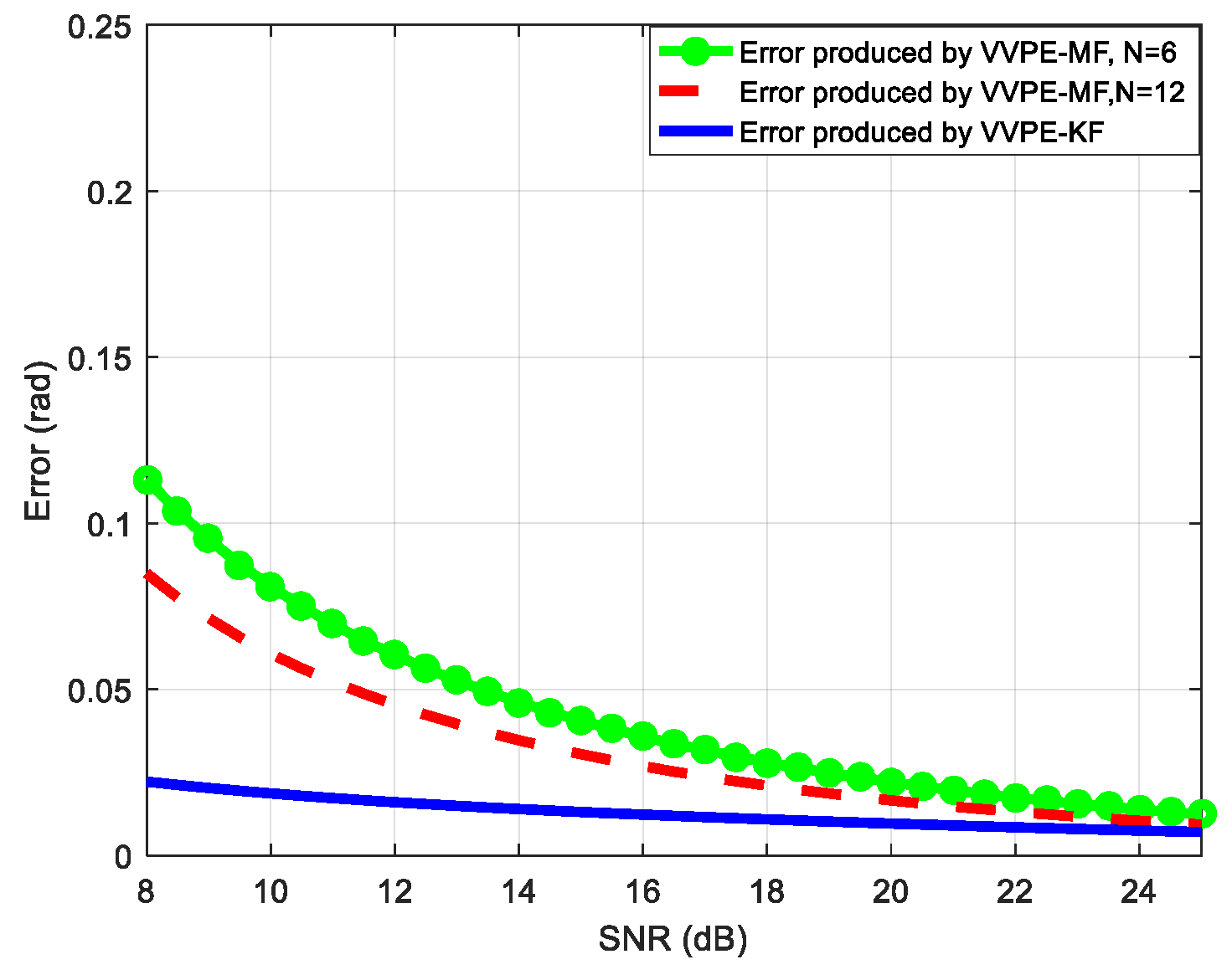
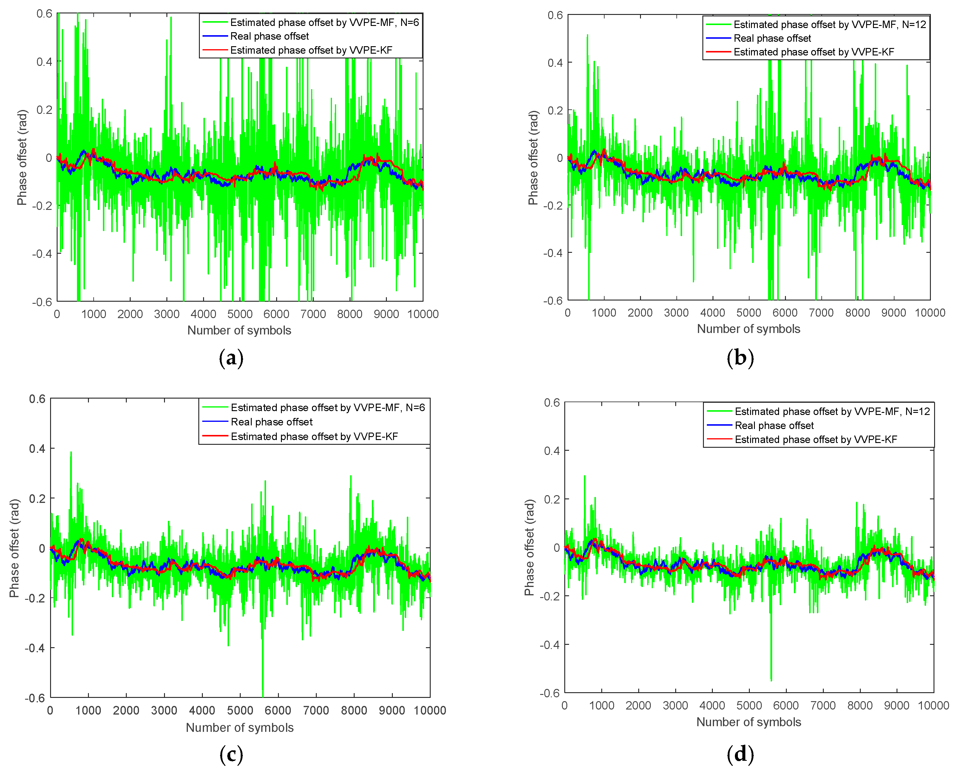
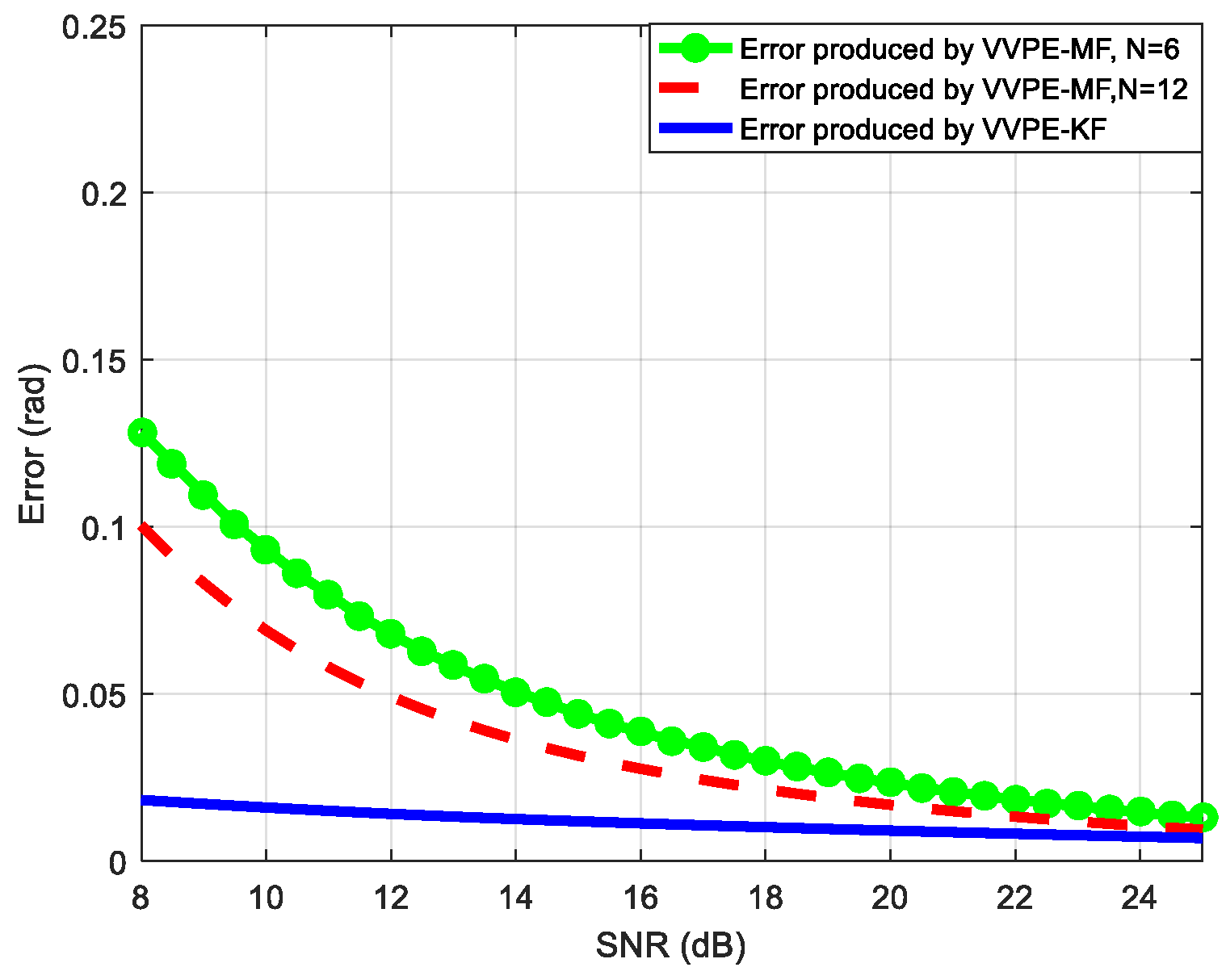
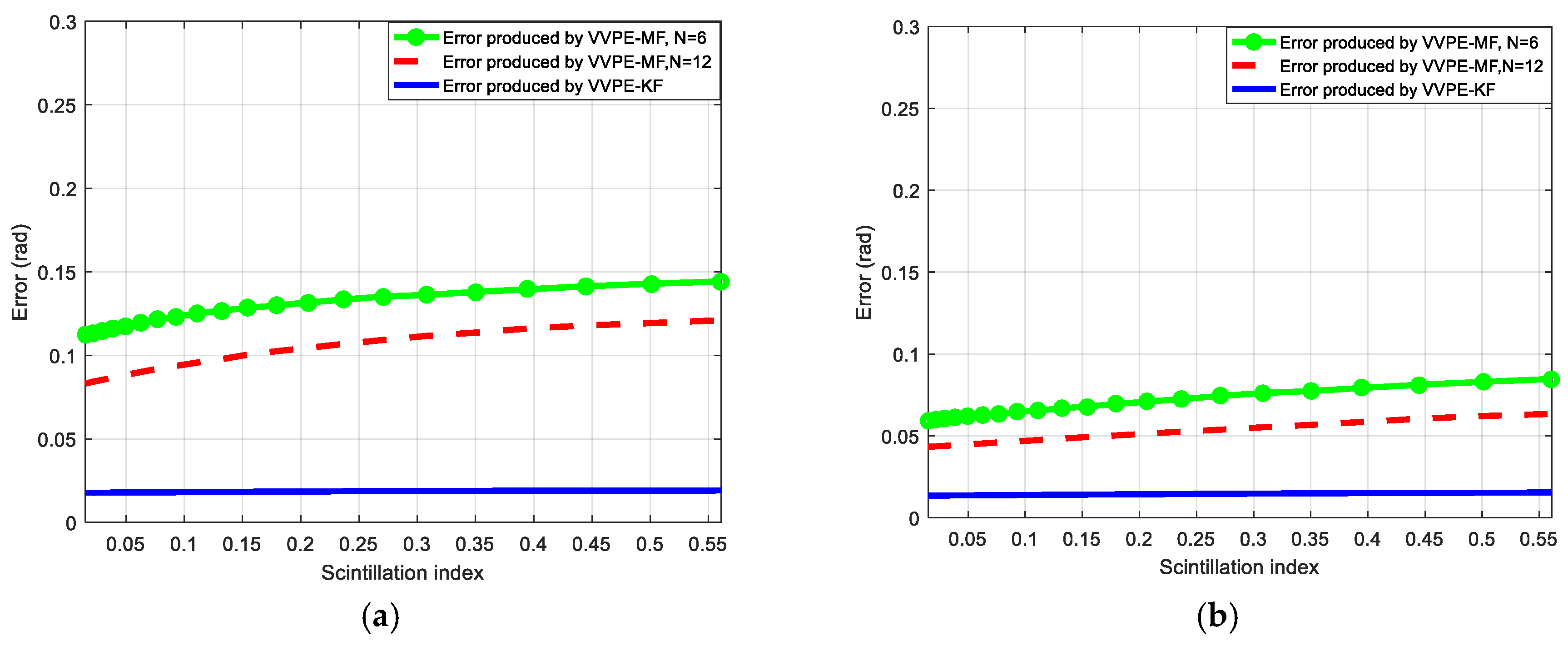
To reduce the estimation error, a new algorithm combining VVPE with the Kalman filter (VVPE-KF) is presented in this paper. The Kalman Filter is considered as an optimal filter, by which the measurement values and prediction values are fused together. To estimate the phase offset, a one-order Kalman filter is employed.
The input of the Kalman filter x i = r k 4 = ( A k s k + n k ) 4 is the fourth power of real received symbol r k including the channel gain and noise. The output of the Kalman filter x o = [ A k 4 s k 4 ] is the estimation of [ A k s k ] 4 , which is the value of the signal symbol A ( k ) s k after being raised to the fourth power. Then calculating the angle of [ A k 4 s k 4 ] , the estimated phase offset θ k can be obtained.
The measurement equation of this Kalman filter is:
z k = H s k 4 + v k
z k is the measurement value and H is the measurement matrix set to be 1 in this one-order Kalman filter. v k is the measurement noise with its variance R . According to the Winner process described in Equation (7), the phase offset in k 1 time slot and k time slot can be considered to be equal approximately, thus the state prediction equation is expressed as:
s k 4 = Φ k / k 1 s k 1 4 + w k 1
Φ k / k 1 is the state transition matrix and it is set to be 1. w k 1 is the prediction noise whose variance is Q . Based on the fusion principle of Kalman filter, the output of the filter is:
r k 4 = r k 1 4 + K f ( z k r k 1 4 )
The Kalman gain K f in one-order Kalman filter can be obtained by:
K f = P ( k / k 1 ) P ( k / k 1 ) + R
where P ( k / k 1 ) is the covariance of the prediction error and it can be calculated as:
P ( k / k 1 ) = P ( k 1 ) + Q
P ( k 1 ) is the covariance of current error in k 1 time plot. The covariance of the estimation error in the k time plot is renewed as:
P ( k ) = ( 1 K f ) P ( k / k 1 )
A total iteration is finished by (16)–(20). The schematic of the VVPE-KF used to estimate the phase offset for QPSK modulation is shown as Figure 2. By the delay device in the figure, the estimation of the previous time slot is stored temporarily. Then the prediction of the last time slot and the current measurement are forged together.

4. Number Results

In this section, we present the simulation experience results of the VVPE-KF and the VVPE-MF is used as a reference. We consider the variance of the measurement noise R and the variance of prediction noise Q of the Kalman filter as the variance of n k in Equation (5) and the variance of f i described as Equation (7) approximately, respectively. The variance σ f 2 in Equation (8) is assumed as 3.14 × 10 6 . The parameters of the Kalman estimator P ( k / k 1 ) , P ( k ) and K f are all initialized to be 0.1 and the estimator can get convergence within 30 iterations. The SNR in this paper is defined as the average ratio of the received symbol power to the noise variance.
Figure 3 illustrates the effectiveness in tracking the phase offset by VVPE-MF (N = 6), VVPE-MF (N = 12) and VVPE-KF with various SNR (10 and 15 dB). The atmosphere turbulence is ignored, and the channel gain is assumed as a constant. The tracking curves of VVPE-KF can approximate the real phase offset closely and the VVPE-MF curves fluctuated severely.
To evaluate the performance of the estimation method further, we demonstrate the estimation error of VVPE-KF and VVPE-MF against SNR in Figure 4. This error is defined as:
E r r o r = 1 L k = 1 L | θ k θ k |
which is the absolute value of the mean difference between the estimated phase offset θ k and the real phase offset θ k . L is set to be 10 4 . It is observed that the VVPE-KF has definite advantage over VVPE-MF especially with low SNR. For example, when the SNR is 10, the error produced by VVPE-KF is one third of VVPE-MF (N = 12) error and one fourth of VVPE-MF (N = 6) error.
In coherent space optical signal receiver, the received modulated optical signal through the atmosphere is affected by the atmosphere turbulence. To evaluate the performance of VVPE-KF with the atmosphere turbulence, we employ a group of experience data collected by the ground station of the quantum communication satellite located in Xinjiang of China. Figure 5a shows a group of normalized channel gain (optical irradiance) values and its histogram. Processing this group of data using the method described in Section 2.1, we can obtain the data shown in Figure 5b,c. With the scintillation index increasing, more information symbols with low SNR appears and the more precise phase offset estimation method is demanded for.
Figure 6 presents the curves of the tracking phase offset by VVPE-KF and VVPE-MF with atmosphere turbulence. The same as Figure 3, the real phase offset is simulated by Equation (7). The received signal containing channel gain and noise described as Equation (5) is used to simulate the performance of the phase offset estimation methods. The fluctuated optical irradiance in Figure 5b is used as channel gain A k .
Compared with the performance without turbulence shown in Figure 3, the error of the VVPE-MF is greater within the local range as a result of the fluctuated optical intensity and the performance of VVPE-KF keeps better obviously.
To present the performance improvement of VVPE-KF quantitatively, Figure 7 demonstrates the estimation errors of the two methods. Comparing with Figure 4, the error of VVPE-MF is greater than Figure 4. Because of the atmosphere turbulence, there are channel gain samples moving towards zero and more low SNR symbols appearing. The greater estimation errors of VVPE-MF are caused by these low SNR symbols. However, the obvious advantage of VVPE-KF is kept.
The intensity probability density of the received optical signal depends on the scintillation index. With the scintillation index increasing, there are more samples of channel gain near to zero. In Figure 8, the impact of various scintillation indexes on the estimation error is demonstrated and two SNR values (SNR = 8 dB, SNR = 12 dB) are employed. With the turbulence increasing, the errors of the offset estimation algorithm increase too. The performance of VVPE-KF is more stable and the estimation accuracy of VVPE-MF is more sensitive to atmosphere intensity.
According to the number results, the performance of the VVPE-KF is better than the VVPE-MF, which results from the Kalman filter theory. Comparing with the information symbols rate, the phase offset changes much more slowly. Several adjacent phase offset values can be considered as the same approximately, thus, the prediction equation can be obtained precisely. The measurement values containing noise are forged with the prediction values with the least square error criterion by Kalman filter, by which the VVPE-KF can be considered to an optimized signal processing method.

5. Conclusions and Future Work

In this paper, a new phase offset estimation method combining the Viterbi-Viterbi algorithm with the Kalman filter is presented. The number results demonstrate that this method can improve the performance of tracking the phase offset between the local laser in the receiver and the received space optical signal through the atmosphere effectively. This new method can produce less error obviously, especially with a low SNR, whenever the channel gain is constant and time-varying. In addition, this VVPE-KF algorithm has better robustness to atmosphere intensity and SNR. In engineering, the coherent optical receiver with a larger aperture can depress the optical irradiance scintillation effectively and support the high SNR. However, large aperture produces high cost and severe wave front aberration, which can degrade the communication performance inevitably. Another method to improve the communication performance is using the coherent receiver with multiple small apertures, in which the SNR is low, and the optical irradiance fluctuates seriously. The VVPE-KF can estimate the phase offset precisely for this multiple-aperture receiver, which is a research hotspot. For coherent diversity receiving, the frequency offset and channel gain are important information, thus the next work is to design an appropriate algorithm to estimate the frequency offset between the local laser and the received signal and the fluctuated channel gain caused by the atmosphere turbulence.

Author Contributions

Conceptualization, H.L. and Y.H.; methodology, H.L. and Y.H.; software, H.L. and Q.W.; validation, H.L. and D.H.; formal analysis, D.H.; investigation, D.H.; resources, H.L. and Q.W.; data curation, Q.L.; writing—original draft preparation, H.L.; writing—review and editing, H.L. and Z.P.; visualization, H.L.; supervision, Y.H.; project administration, Q.W.; funding acquisition, Y.H. and Z.P.

Funding

This research was funded by National Natural Science Foundation of China, grant number: 61571096.

Conflicts of Interest

The authors declare no conflict of interest.

References

  1. Kaushal, H.; Kaddoum, G. Optical communication in space: Challenges and mitigation techniques. IEEE Commun. Surv. Tutor. 2017, 19, 57–96. [Google Scholar] [CrossRef]
  2. Niu, M.; Cheng, J.; Holzman, J.F. Error rate analysis of M-Ary coherent free-space optical communication systems with k-distributed turbulence. IEEE Trans. Commun. 2011, 59, 664–668. [Google Scholar] [CrossRef]
  3. Li, M.; Hong, Y.; Zeng, C.; Song, Y.; Zhang, X. Investigation on the UAV-to-satellite optical communication systems. IEEE J. Sel. Areas Commun. 2018, 36, 2128–2138. [Google Scholar] [CrossRef]
  4. Khalighi, M.A.; Uysal, M. Survey on free space optical communication: A communication theory perspective. IEEE Commun. Surv. Tutor. 2014, 16, 2231–2258. [Google Scholar] [CrossRef]
  5. Niu, M.; Song, X.; Cheng, J.; Holzman, J.F. Performance analysis of coherent wireless optical communications with atmospheric turbulence. Opt. Express 2012, 20, 6515–6521. [Google Scholar] [CrossRef] [PubMed]
  6. Niu, M.; Cheng, J.; Holzman, J.F. MIMO architecture for coherent optical wireless communication: System design and performance. J. Opt. Commun. Netw. 2013, 5, 411–420. [Google Scholar] [CrossRef]
  7. Ipp, E. Coherent detection in optical fiber systems. Opt. Express 2008, 16, 753–791. [Google Scholar] [CrossRef]
  8. Li, G. Recent advances in coherent optical communication. Adv. Opt. Photonics 2009, 1, 279–307. [Google Scholar] [CrossRef]
  9. Yang, L.; Shoufeng, T.; Shuai, C. Design of a delayed XOR phase detector for an optical phase-locked loop toward high-speed coherent laser communication. Appl. Optics 2018, 57, 3770–3780. [Google Scholar]
  10. Shamsul, A.; Arda, S.; Mingzhi, L.; Rodwell, M.J.; Coldren, L.A. Heterodyne locking of a fully integrated optical phase-locked loop with on-chip modulators. Opt. Lett. 2017, 42, 3745–3748. [Google Scholar]
  11. Faruk, M.S.; Louchet, H.; Erkılınç, M.S.; Savory, S.J. DSP algorithms for recovering single-carrier Alamouti coded signals for PON applications. Opt. Express 2016, 24, 24083–24091. [Google Scholar] [CrossRef] [PubMed]
  12. Schaefer, S.; Gregory, M.; Rosenkranz, W. Coherent receiver design based on digital signal processing in optical high-speed intersatellite links with M-phase-shift keying. Opt. Eng. 2016, 55, 111614. [Google Scholar] [CrossRef]
  13. Kazovsky, L.G.; Kalogerakis, G.; Shaw, W.T. Homodyne phase-shift-keying systems: Past challenges and future opportunities. J. Light. Technol. 2006, 24, 4876–4884. [Google Scholar] [CrossRef]
  14. Robinson, B.S.; Schieler, C.M.; Geisler, D.J.; Stevens, M.L.; Hamilton, S.A.; Yarnall, T.M. Multi-aperture digital coherent combining for free-space optical communication receivers. Opt. Express 2016, 24, 12661–12671. [Google Scholar]
  15. Hoffmann, S.; Peveling, R.; Pfau, T.; Adamczyk, O.; Eickhoff, R.; Reinhold, N. Multiplier-free real-time phase tracking for coherent QPSK receivers. IEEE Photonics Technol. Lett. 2009, 21, 137–139. [Google Scholar] [CrossRef]
  16. Zafra, S.O.; Pang, X.; Jacobsen, G.; Popov, S.; Sergeyev, S. Phase noise tolerance study in coherent optical circular QAM transmissions with Viterbi-Viterbi carrier phase estimation. Opt. Express 2014, 22, 30579–30585. [Google Scholar] [CrossRef] [PubMed]
  17. Fatadin, I.; Ives, D.; Savory, S.J. Differential carrier phase recovery for QPSK optical coherent systems with integrated tunable lasers. Opt. Express 2013, 21, 10166–10171. [Google Scholar] [CrossRef] [PubMed]
  18. Katsis, A.; Nistazakis, H.E.; Tombras, G.S. Bayesian and frequentist estimation of the performance of free space optical channels under weak turbulence conditions. J. Franklin Inst. 2009, 346, 315–327. [Google Scholar] [CrossRef]
  19. Andrews, L.C.; Phillips, R.L. Laser Beam Propagation through Random Media, 2nd ed.; SPIE Press: Washington, DC, USA, 2005; pp. 481–496. [Google Scholar]
  20. Ghassemlooy, Z.; Popoola, W.; Rajbhandari, S. Optical Wireless Communications: System and Channel Modelling with MATLAB; CRC Press: New York, NY, USA, 2012; pp. 133–135. [Google Scholar]
  21. Wang, Y.; Serpedin, E.; Ciblat, P. Optimal blind nonlinear least-squares carrier phase and frequency offset estimation for general QAM modulations. IEEE Trans. Wirel. Commun. 2003, 2, 1040–1054. [Google Scholar] [CrossRef]
Figure 1. The schematic of coherent receiver based on DSP (digital signal processing).
Applsci 09 00836 g001
Figure 2. Schematic of the method combining Viterbi-Viterbi phase offset estimation algorithm with the Kalman filter (VVPE-KF).
Applsci 09 00836 g002
Figure 3. The performance of tracking the phase offset by VVPE-KF and VVPE-MF (Viterbi-Viterbi phase offset estimation algorithm with the mean filter) without atmosphere turbulence. The SNR values of (a), (b), (c) and (d) are 10, 10, 15, 15 dB respectively.
Applsci 09 00836 g003
Figure 4. The error produced by VVPE-KF and VVPE-MF without atmosphere turbulence.
Applsci 09 00836 g004
Figure 5. The normalized optical intensity (channel gain) curves and histogram. The scintillation indexes of (a), (b), and (c) are 0.015, 0.154, and 0.561, respectively.
Applsci 09 00836 g005
Figure 6. The performance of tracking the phase offset by VVPE-KF and VVPE-MF with atmosphere turbulence. The SNR vales of (a), (b), (c), and (d) are 10, 10, 15, and 15 dB, respectively.
Applsci 09 00836 g006
Figure 7. The error produced by VVPE-KF and VVPE-MF with atmosphere turbulence.
Applsci 09 00836 g007
Figure 8. The impact of various scintillation indexes on the estimation error of VVPE-KF and VVPE-MF. The SNR values of (a) and (b) are 8 and 12 dB respectively.
Applsci 09 00836 g008

