Effect of Carbon Nanotubes on Chloride Penetration in Cement Mortars

 ,
,  ,
, 
Abstract
:1. Introduction
2. Experimental Procedures
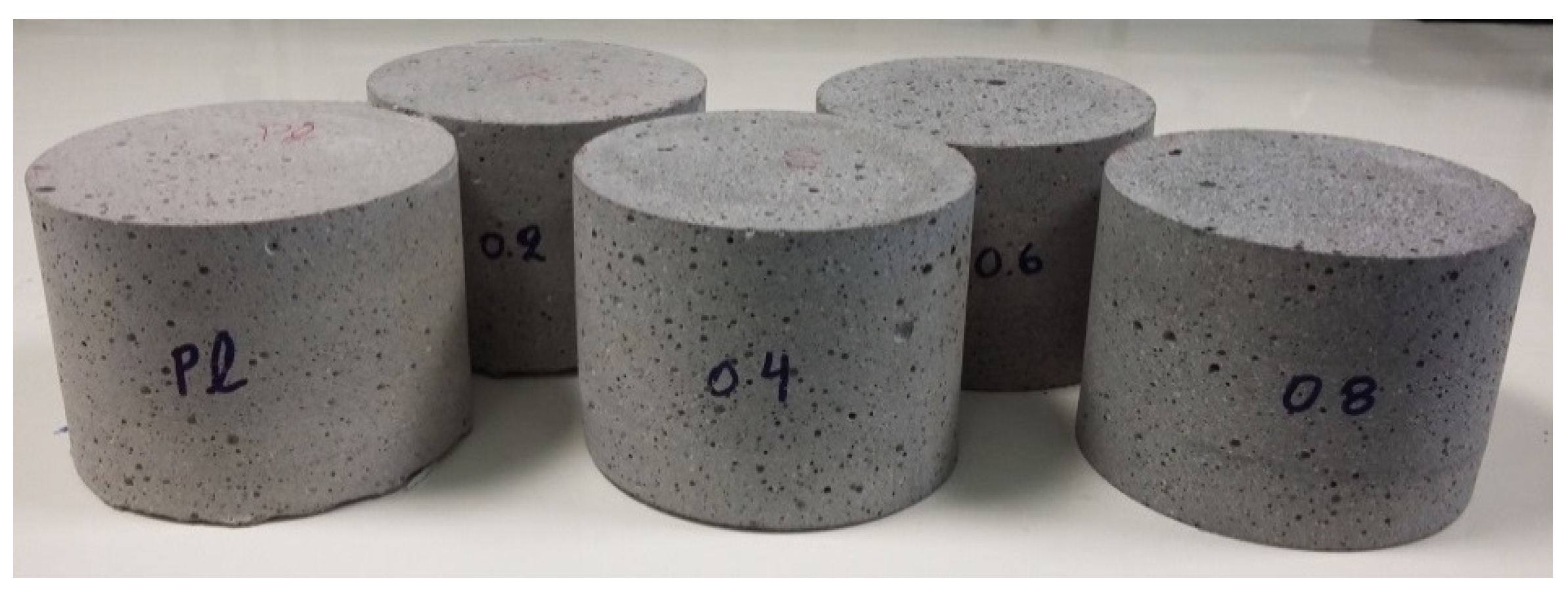
2.1. Materials and Specimens
2.2. Properties in Fresh Conditions
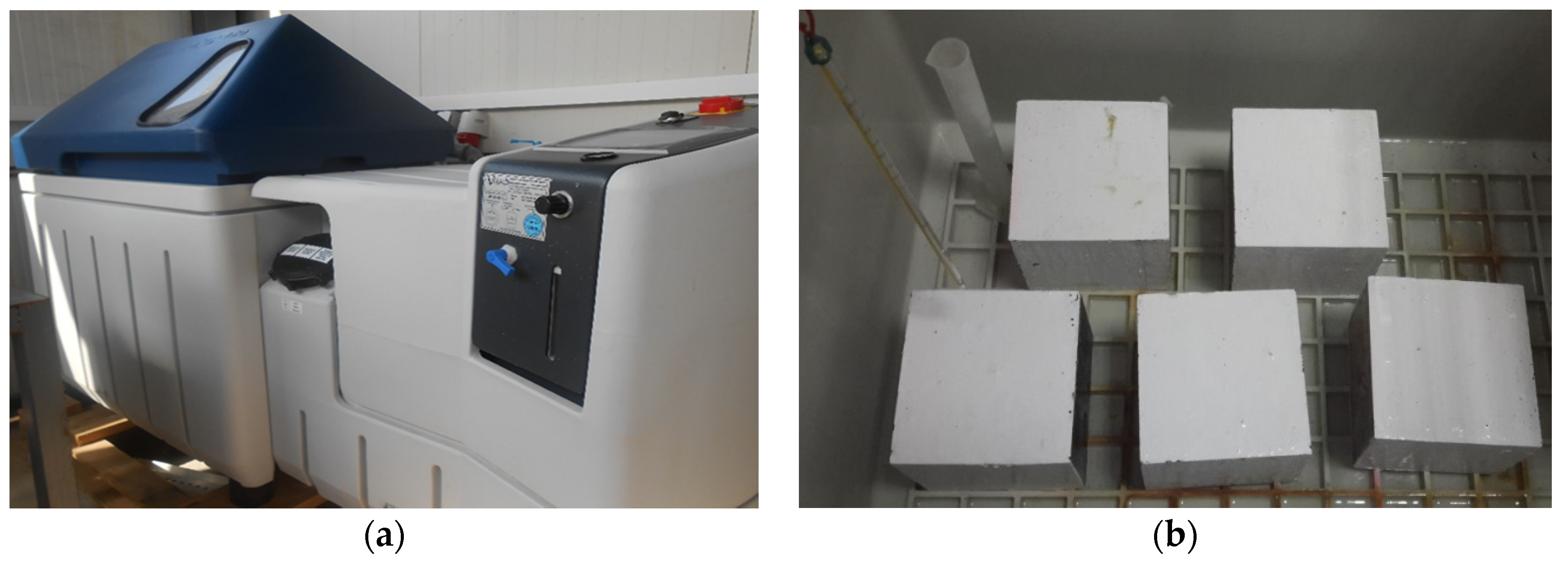
2.3. Chloride Penetration
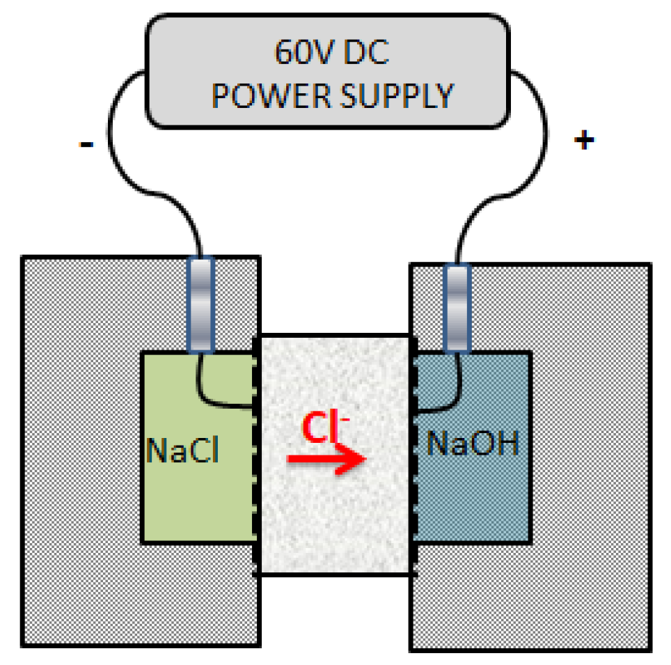
2.3.1. RCPT Method
2.3.2. RCT Method
2.4. Porosimetry
2.5. Electrical Conductivity Measurements
2.6. Mechanical Performance
3. Results and Discussion
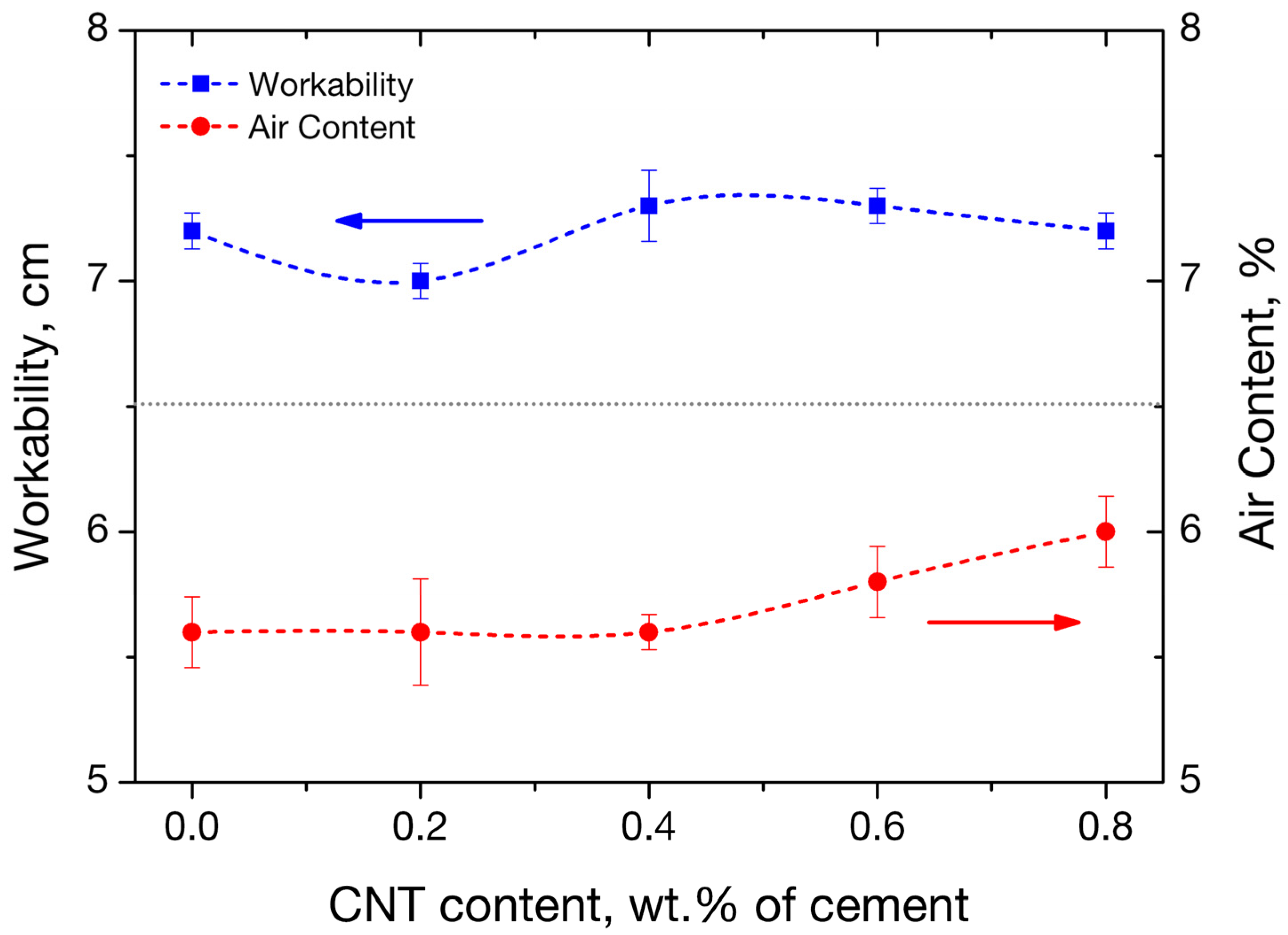
3.1. Workability and Air Content of Fresh Mortars
3.2. Chloride Profile of the CNTs Nano-Modified Mortars
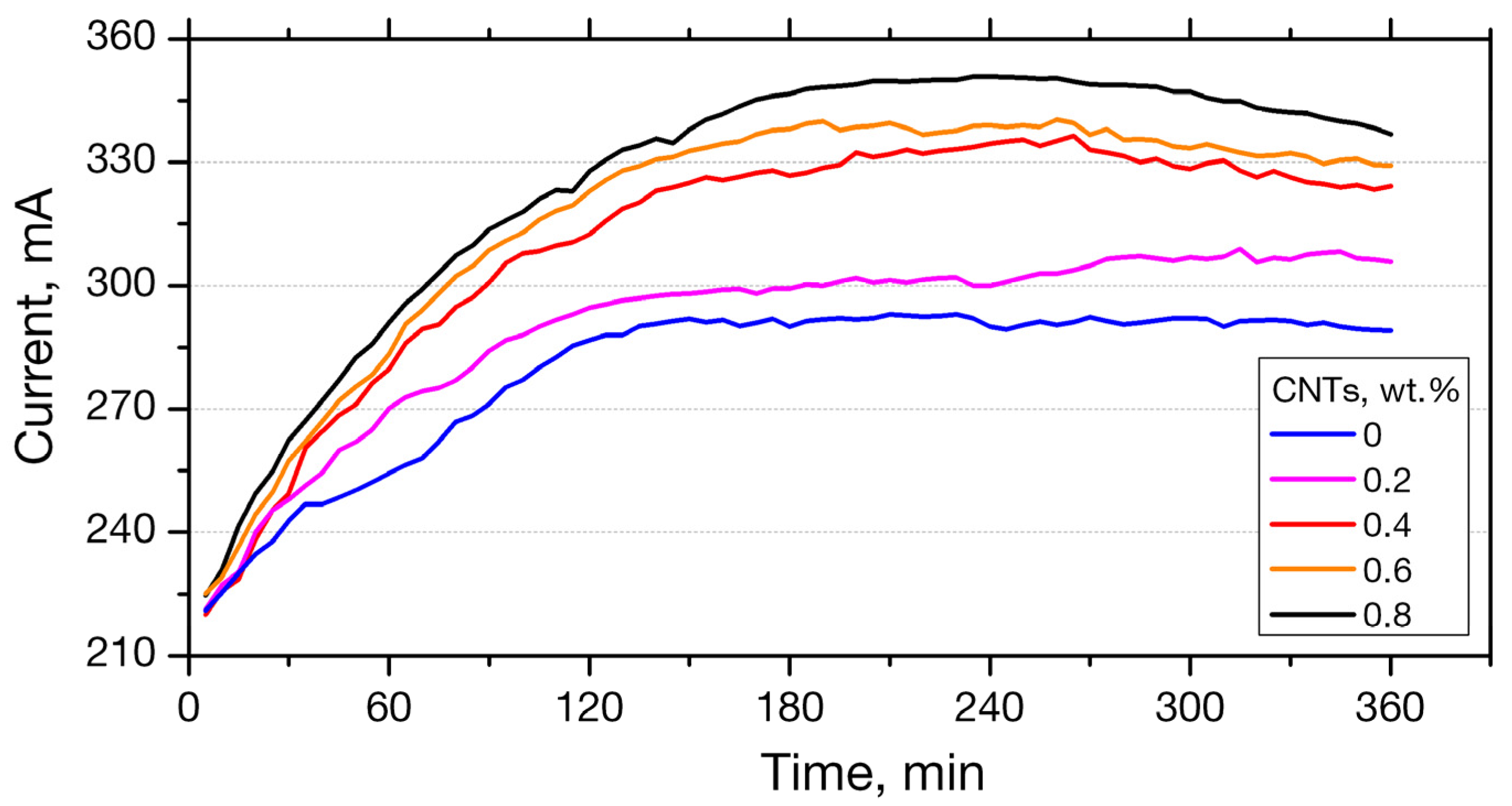
3.2.1. RCPT Method
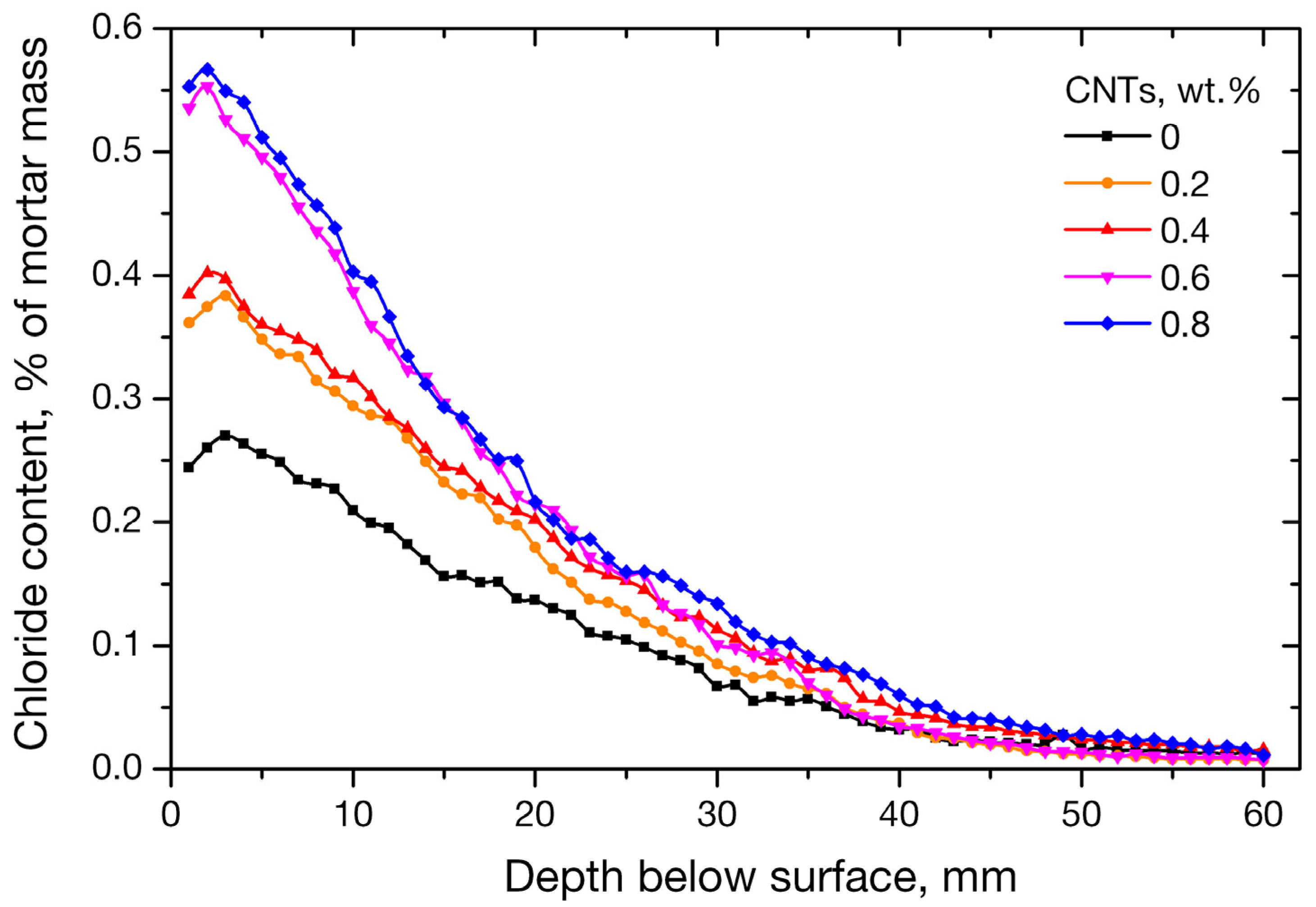
3.2.2. RCT Method
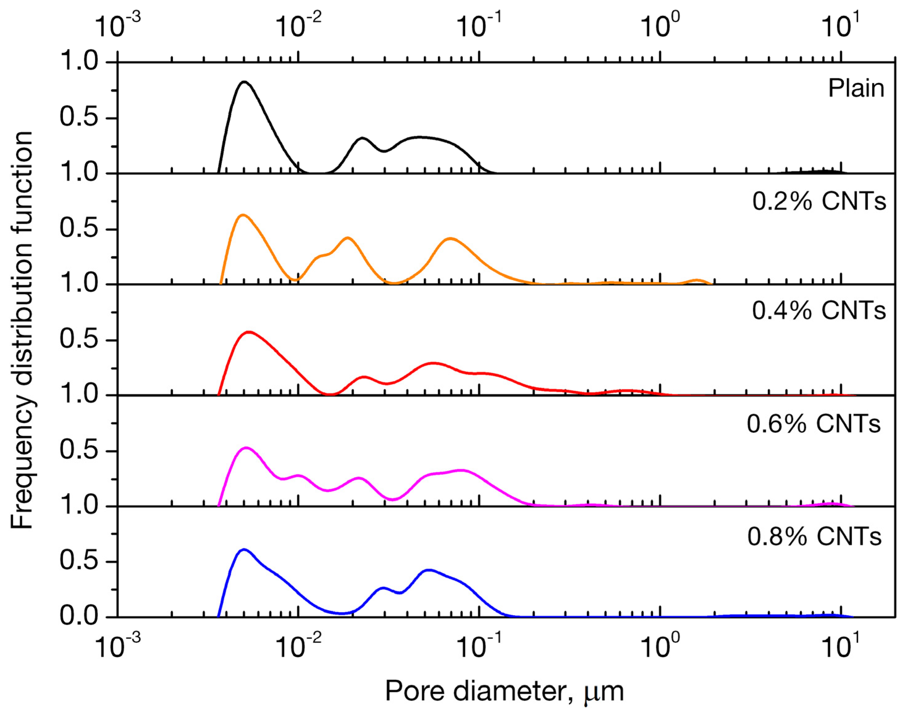
3.3. Porosity
3.4. Electrical Properties of Nano-Modified Mortars
3.5. Mechanical Performance of Nano-Modified Mortars
4. Conclusions
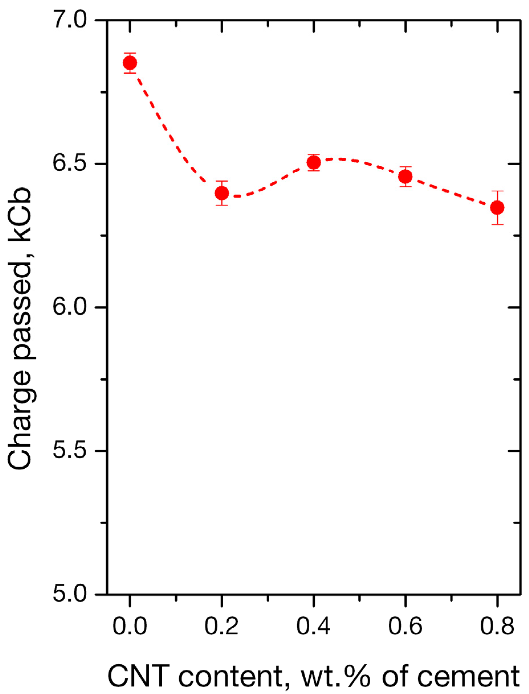
- Using the rapid chloride permeability test method (RCPT) for plain and nano-reinforced mortars, all mortars were observed to exhibit high ion permeability. It must not be neglected that the RCPT-measurable permeability reflects not only chloride ions, but the total of ions contained to the mixture.
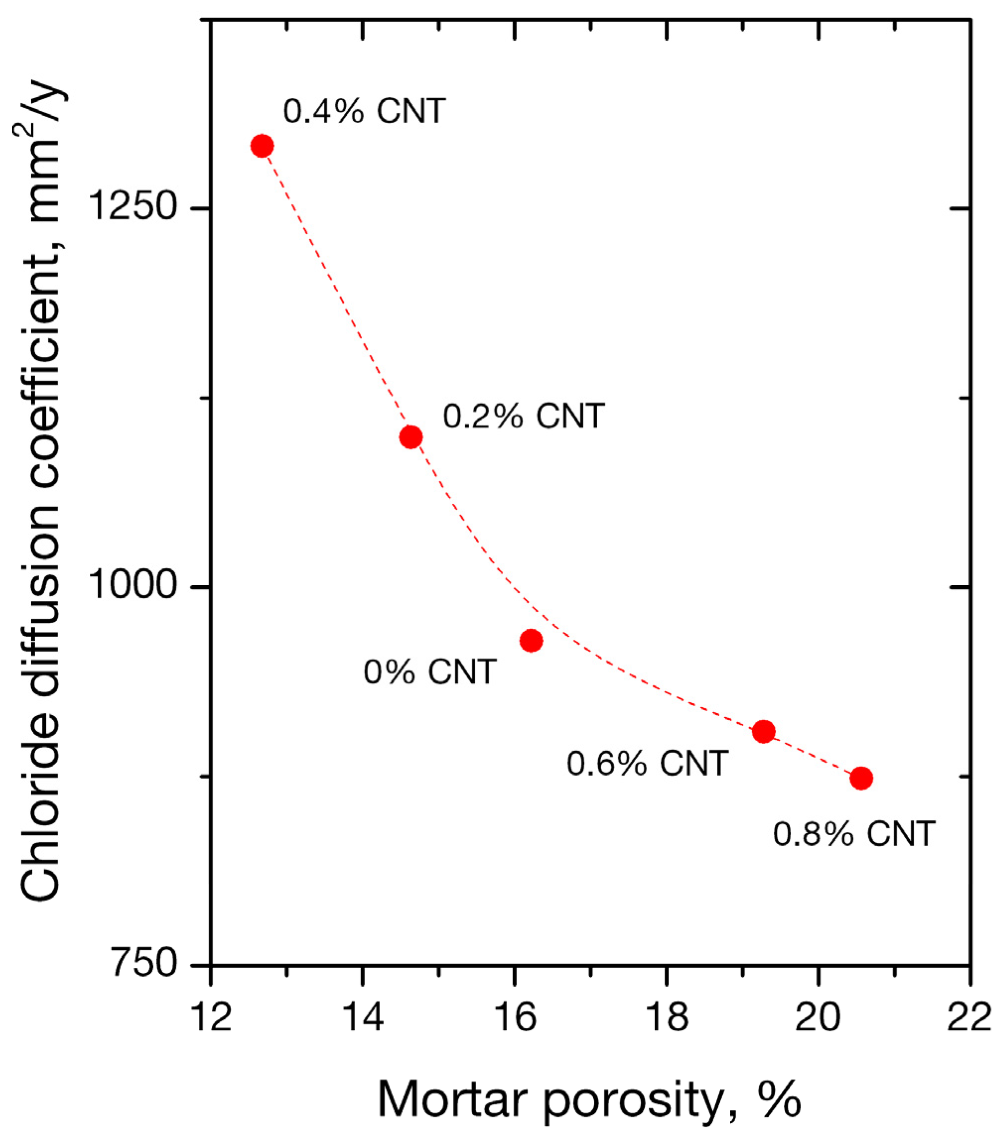
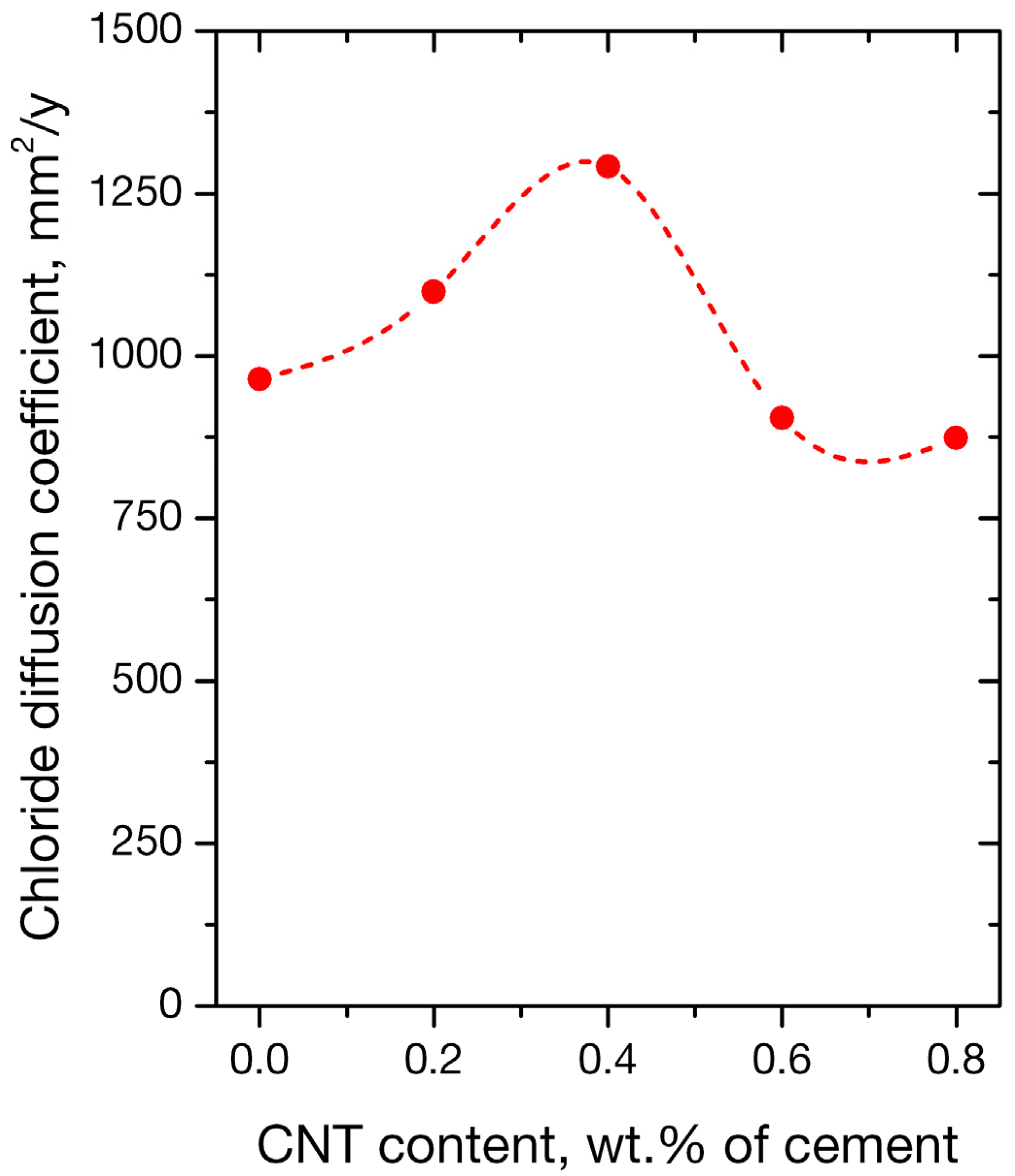
- Nano-inclusions were found to affect the permeability of the mortars since the absorbed ion chlorides increased with nanotube concentration. Diffusion coefficient (Da) did not follow the same trend; it increased up to 0.4 wt. % of nanofiller content and decreased for higher contents of 0.6% and 0.8%. Porosimetry findings are compatible with the observed behavior.
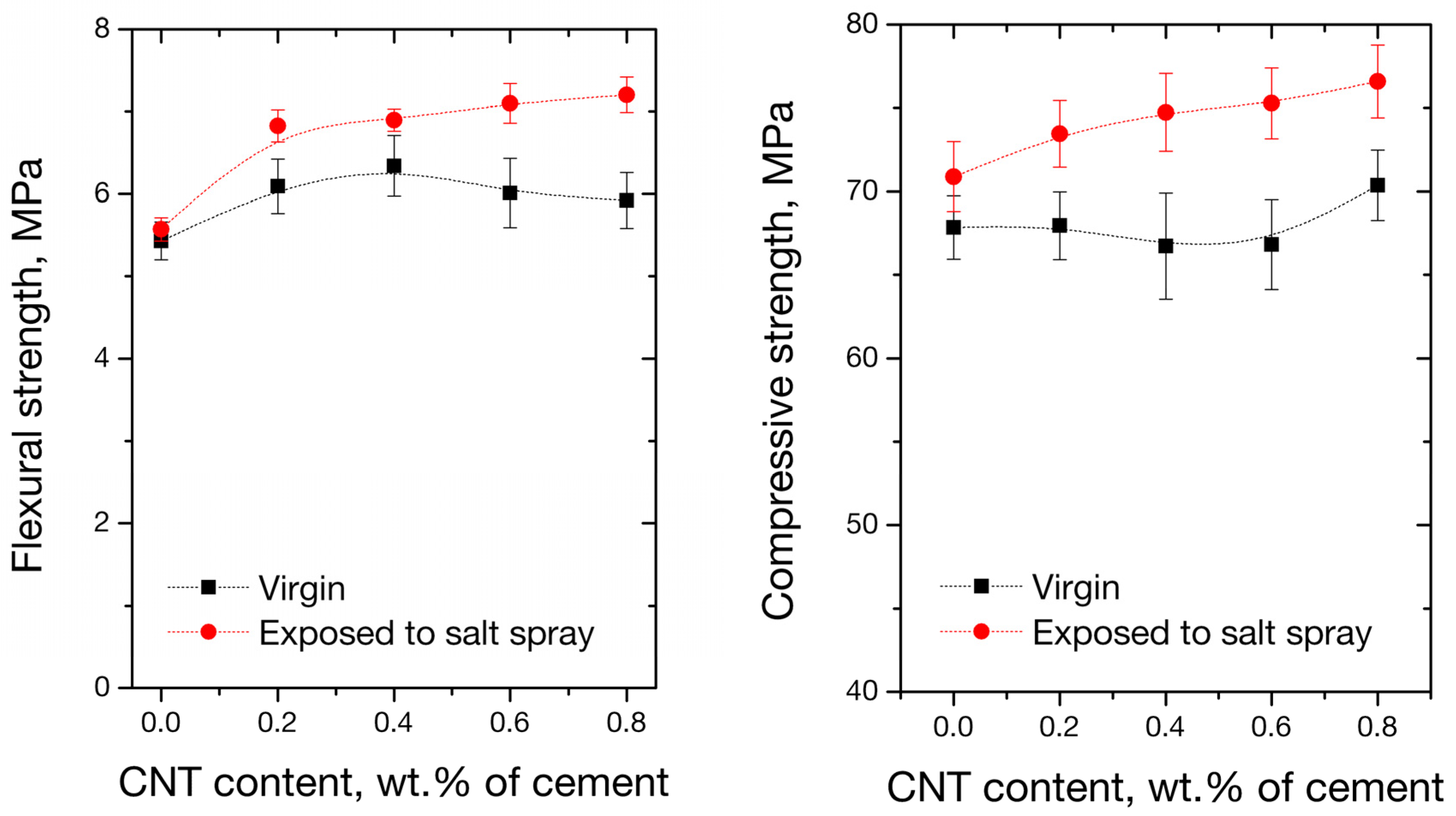
- The flexural and compressive properties of mortars exposed to salt spray fog present improved values compared to the virgin specimens. The observed improvement was rationalized upon sodium chloride filling the pores, which resulted in a decrease in apparent porosity and an increase in material strength.
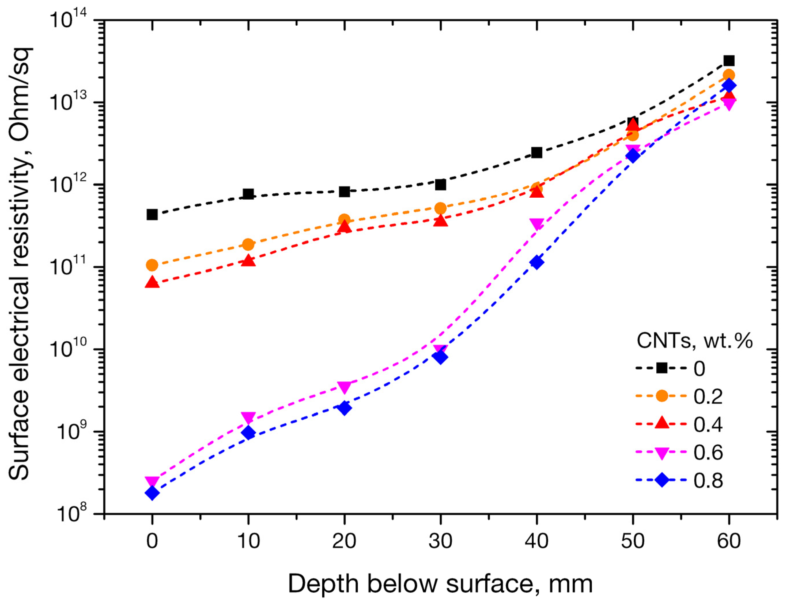
- Electrical resistivity, measured incrementally every 10 mm below the surface of the specimen, presented notable variations as a result of the specimens’ subjection to NaCl solution. For mortars with 0, 0.2, and 0.4 wt. % CNTs, resistivity increased up to two orders of magnitude with interrogation depth. On the other hand, mortars with percolated conductive nanofiller networks at CNT concentrations of 0.6 and 0.8 wt. % CNTs, exhibited increases in electrical resistivity up to five orders of magnitude with respect to the surface value.
Author Contributions
Funding
Conflicts of Interest
References
- Sanchez, F.; Sobolev, K. Nanotechnology in concrete—A review. Constr. Build. Mater. 2010, 24, 2060–2071. [Google Scholar] [CrossRef]
- Dalla, P.T.; Dassios, K.G.; Tragazikis, I.K.; Exarchos, D.A.; Matikas, T.E. Carbon nanotubes and nanofibers as strain and damage sensors for smart cement. Mater. Today Commun. 2016, 8, 196–204. [Google Scholar] [CrossRef]
- Tragazikis, I.; Dalla, P.; Exarchos, D.; Dassios, K.; Matikas, T. Nondestructive evaluation of the mechanical behavior of cement based nanocomposites under bending. Proc. SPIE 2015, 9436, 94360F. [Google Scholar]
- Kawashima, S.; Seo, J.-W.T.; Corr, D.; Hersam, M.C.; Shah, S.P. Dispersion of CaCO3 nanoparticles by sonication and surfactant treatment for application in fly ash–cement systems. Mater. Struct. 2014, 47, 1011–1023. [Google Scholar] [CrossRef]
- Hou, P.; Qian, J.; Cheng, X.; Shah, S.P. Effects of the pozzolanic reactivity of nanoSiO2 on cement-based materials. Cem. Concr. Compos. 2015, 55, 250–258. [Google Scholar] [CrossRef]
- Jin, M.; Jiang, L.; Lu, M.; Bai, S. Monitoring chloride ion penetration in concrete structure based on the conductivity of graphene/cement composite. Constr. Build. Mater. 2017, 136, 394–404. [Google Scholar] [CrossRef]
- Tragazikis, I.K.; Dassios, K.G.; Dalla, P.T.; Exarchos, D.A.; Matikas, T.E. Acoustic emission investigation of the effect of graphene on the fracture behavior of cement mortars. Eng. Fract. Mech. 2018, in press. [Google Scholar] [CrossRef]
- Tragazikis, I.K.; Dassios, K.G.; Exarchos, D.A.; Dalla, P.T.; Matikas, T.E. Acoustic emission investigation of the mechanical performance of carbon nanotube-modified cement-based mortars. Constr. Build. Mater. 2016, 122, 518–524. [Google Scholar] [CrossRef]
- Dheeraj Swamy, B.L.P.; Raghavan, V.; Srinivas, K.; Narasinga Rao, K.; Lakshmanan, M.; Jayanarayanan, K.; Mini, K.M. Influence of silica based carbon nano tube composites in concrete. Adv. Compos. Lett. 2017, 26, 12–17. [Google Scholar]
- Du, H.; Gao, H.J.; Pang, S.D. Improvement in concrete resistance against water and chloride ingress by adding graphene nanoplatelet. Cem. Concr. Res. 2016, 83, 114–123. [Google Scholar] [CrossRef]
- Darmawan, M.S.; Bayuaji, R.; Husin, N.A.; Anugraha, R.B. Case Study of Remaining Service Life Assessment of a Cooling Water Intake Concrete Structure in Indonesia. Adv. Civ. Eng. 2014, 2014, 16. [Google Scholar] [CrossRef]
- Hodhod, O.A.; Ahmed, H.I. Modeling the service life of slag concrete exposed to chlorides. Ain Shams Eng. J. 2014, 5, 49–54. [Google Scholar] [CrossRef] [Green Version]
- Neville, A. Chloride attack of reinforced concrete: An overview. Mater. Struct. 1995, 28, 63. [Google Scholar] [CrossRef]
- Zhu, J.; Zhang, Y.; Zhao, D. Durability Assessment of an RC Railway Bridge Pier under a Chloride-Induced Corrosion Environment. In Proceedings of the Fifth International Conference on Transportation Engineering, Dalian, China, 26–27 September 2015. [Google Scholar]
- Zeng, L.; Song, R. Controlling chloride ions diffusion in concrete. Sci. Rep. 2013, 3, 3359. [Google Scholar] [CrossRef]
- Song, Z.; Jiang, L.; Liu, J.; Liu, J. Influence of cation type on diffusion behavior of chloride ions in concrete. Constr. Build. Mater. 2015, 99, 150–158. [Google Scholar] [CrossRef]
- Otieno, M.; Beushausen, H.; Alexander, M. Chloride-induced corrosion of steel in cracked concrete – Part I: Experimental studies under accelerated and natural marine environments. Cem. Concr. Res. 2016, 79, 373–385. [Google Scholar] [CrossRef]
- Stanish, K.D.; Hooton, R.D.; Thomas, M.D. Testing the Chloride Penetration Resistance of Concrete: A Literature Review; FHWA Contract DTFH61; Department of Civil Engineering, University of Toronto: Toronto, ON, Canada, 1997. [Google Scholar]
- Liang, M.T.; Wang, K.L.; Liang, C.H. Service life prediction of reinforced concrete structures. Cem. Concr. Res. 1999, 29, 1411–1418. [Google Scholar] [CrossRef]
- Liang, M.T.; Hong, C.L.; Liang, C.H. Service life prediction of existing reinforced concrete structures under carbonation-induced corrosion. J. Chin. Inst. Civ. Hydraul. Eng. 1999, 11, 485–492. [Google Scholar]
- Morinaga, S. Prediction of Service Lives of Reinforced Concrete Buildings Based on Rate of Corrosion of Reinforcing Steel; Report No. 23; Shimizu Corp: Tokyo, Japan, 1988; pp. 82–89. [Google Scholar]
- Jamali, A.; Angst, U.; Adey, B.; Elsener, B. Modeling of corrosion-induced concrete cover cracking: A critical analysis. Constr. Build. Mater. 2013, 42, 225–237. [Google Scholar] [CrossRef]
- Ranjith, A.; Rao, K.B.; Manjunath, K. Evaluating the effect of corrosion on service life prediction of RC structures—A parametric study. Int. J. Sustain. Built Environ. 2016, 5, 587–603. [Google Scholar] [CrossRef]
- Roa-Rodriguez, G.; Aperador, W.; Delgado, A. Calculation of Chloride Penetration Profile in Concrete Structures. Int. J. Electrochem. Sci. 2013, 8, 5022–5035. [Google Scholar]
- Kim, H.K.; Jang, J.G.; Choi, Y.C.; Lee, H.K. Improved chloride resistance of high-strength concrete amended with coal bottom ash for internal curing. Constr. Build. Mater. 2014, 71, 334–343. [Google Scholar] [CrossRef]
- Liang, M.T.; Huang, R.; Feng, S.A.; Yeh, C.J. Service life prediction of pier for the existing reinforced concrete bridges in chloride-laden environment. J. Mar. Sci. Technol. 2009, 17, 312–319. [Google Scholar]
- Gergely, J.; Bledsoe, J.E.; Tempest, B.Q.; Szabo, I.F. Concrete Diffusion Coefficients and Existing Chloride Exposure in North Carolina; Project No. HWY-2004-12; Department of Civil Engineering, University of North Carolina at Charlotte: Charlotte, NC, USA, 2006. [Google Scholar]
- Altaf Ahmad, A.K. Chloride ion migration/diffusion through concrete and test methods. Int. J. Adv. Sci. Tech. Res. 2013, 6, 151–180. [Google Scholar]
- Angst, U.; Elsener, B.; Larsen, C.K.; Vennesland, Ø. Critical chloride content in reinforced concrete—A review. Cem. Concr. Res. 2009, 39, 1122–1138. [Google Scholar] [CrossRef]
- Paul, A.; Laurila, T.; Vuorinen, V.; Divinski, S.V. Fick’s Laws of Diffusion. In Thermodynamics, Diffusion and the Kirkendall Effect in Solids; Springer International Publishing: Cham, Switzerland, 2014; pp. 115–139. [Google Scholar]
- Bertolini, L.; Elsener, B.; Pedeferri, P.; Polder, R. Corrosion of Steel in Concrete: Prevention, Diagnosis, Repair; Wiley-VCH: Weinheim, Germany, 2004. [Google Scholar]
- Shi, X.; Yang, Z.; Liu, Y.; Cross, D. Strength and corrosion properties of Portland cement mortar and concrete with mineral admixtures. Constr. Build. Mater. 2011, 25, 3245–3256. [Google Scholar] [CrossRef]
- Kosior-Kazberuk, M.; Jezierski, W. Evaluation of concrete resistance to chloride ions penetration by means of electric resistivity monitoring. J. Civ. Eng. Manag. 2005, 11, 109–114. [Google Scholar] [CrossRef]
- Liu, J.; Wang, X.; Qiu, Q.; Ou, G.; Xing, F. Understanding the effect of curing age on the chloride resistance of fly ash blended concrete by rapid chloride migration test. Mater. Chem. Phys. 2017, 196, 315–323. [Google Scholar] [CrossRef]
- Dodds, W.; Christodoulou, C.; Goodier, C.; Austin, S.; Dunne, D. Durability performance of sustainable structural concrete: Effect of coarse crushed concrete aggregate on rapid chloride migration and accelerated corrosion. Constr. Build. Mater. 2017, 155, 511–521. [Google Scholar] [CrossRef] [Green Version]
- Ying, J.; Zhou, B.; Xiao, J. Pore structure and chloride diffusivity of recycled aggregate concrete with nano-SiO2 and nano-TiO2. Constr. Build. Mater. 2017, 150, 49–55. [Google Scholar] [CrossRef]
- Snyder, K.A.; Ferraris, C.; Martys, N.S.; Garboczi, E.J. Using Impedance Spectroscopy to Assess the Viability of the Rapid Chloride Test for Determining Concrete Conductivity. J. Res. Natl. Inst. Stand. Technol. 2000, 105, 497–509. [Google Scholar] [CrossRef]
- Valipour, M.; Shekarchi, M.; Arezoumandi, M. Chlorine diffusion resistivity of sustainable green concrete in harsh marine environments. J. Clean. Prod. 2017, 142, 4092–4100. [Google Scholar] [CrossRef]
- Madani, H.; Bagheri, A.; Parhizkar, T.; Raisghasemi, A. Chloride penetration and electrical resistivity of concretes containing nanosilica hydrosols with different specific surface areas. Cem. Concr. Compos. 2014, 53, 18–24. [Google Scholar] [CrossRef]
- Song, Z.; Jiang, L.; Zhang, Z.; Xiong, C. Distance-associated chloride binding capacity of cement paste subjected to natural diffusion. Constr. Build. Mater. 2016, 112, 925–932. [Google Scholar] [CrossRef]
- Arya, C.; Buenfeld, N.R.; Newman, J.B. Factors influencing chloride-binding in concrete. Cem. Concr. Res. 1990, 20, 291–300. [Google Scholar] [CrossRef]
- Kim, H.-K. Chloride penetration monitoring in reinforced concrete structure using carbon nanotube/cement composite. Constr. Build. Mater. 2015, 96, 29–36. [Google Scholar] [CrossRef]
- Aldea, C.-M.; Young, F.; Wang, K.; Shah, S.P. Effects of curing conditions on properties of concrete using slag replacement. Cem. Concr. Res. 2000, 30, 465–472. [Google Scholar] [CrossRef]
- Elfmarkova, V.; Spiesz, P.; Brouwers, H.J.H. Determination of the chloride diffusion coefficient in blended cement mortars. Cem. Concr. Res. 2015, 78, 190–199. [Google Scholar] [CrossRef] [Green Version]
- Dalton, R. US researchers fear job losses from privatization drive. Nature 2003, 424, 478. [Google Scholar] [CrossRef]
- Alafogianni, P.; Dassios, K.; Tsakiroglou, C.D.; Matikas, T.E.; Barkoula, N.M. Effect of CNT addition and dispersive agents on the transport properties and microstructure of cement mortars. Constr. Build. Mater. 2019, 197, 251–261. [Google Scholar] [CrossRef]
- Dassios, K.G.; Alafogianni, P.; Antiohos, S.K.; Leptokaridis, C.; Barkoula, N.-M.; Matikas, T.E. Optimization of sonication parameters for homogeneous surfactant-assisted dispersion of multiwalled carbon nanotubes in aqueous solutions. J. Phys. Chem. C 2015, 119, 7506–7516. [Google Scholar] [CrossRef]
- Dalton, R. Museum trustees quit after row over sale of artefacts. Nature 2003, 424, 360. [Google Scholar] [CrossRef] [PubMed]
- Dalton, R. Ants join online colony to boost conservation efforts. Nature 2003, 424, 242. [Google Scholar] [CrossRef] [PubMed]
- ASTM C1202-97—Standard Test Method for Electrical Indication of Concrete’s Ability to Resist Chloride Ion Penetration; ASTM International: West Conshohocken, PA, USA, 1997.
- ASTM B117-16—Standard Practice for Operating Salt Spray (Fog) Apparatus; ASTM International: West Conshohocken, PA, USA, 2016.
- Papadopoulos, M.P.; Apostolopoulos, C.A.; Alexopoulos, N.D.; Pantelakis, S.G. Effect of salt spray corrosion exposure on the mechanical performance of different technical class reinforcing steel bars. Mater. Des. 2007, 28, 2318–2328. [Google Scholar] [CrossRef]
- Crank, J. The Mathematics of Diffusion, 2nd ed.; Clarendon Press: Oxford, UK, 1975. [Google Scholar]
- ASTM C1609/C1609M-05—Standard Test Method for Flexural Performance of Fiber-Reinforced Concrete (Using Beam with Third-Point Loading); ASTM International: West Conshohocken, PA, USA, 2005.
- Alafogianni, P.; Dassios, K.; Farmaki, S.; Antiohos, S.K.; Matikas, T.E.; Barkoula, N.M. On the efficiency of UV–vis spectroscopy in assessing the dispersion quality in sonicated aqueous suspensions of carbon nanotubes. Colloids Surf. A Physicochem. Eng. Asp. 2016, 495, 118–124. [Google Scholar] [CrossRef]
- Nam, I.W.; Choi, J.H.; Kim, C.G.; Lee, H.K. Fabrication and design of electromagnetic wave absorber composed of carbon nanotube-incorporated cement composites. Compos. Struct. 2018, 206, 439–447. [Google Scholar] [CrossRef]
- Jiang, S.; Zhou, D.; Zhang, L.; Ouyang, J.; Yu, X.; Cui, X.; Han, B. Comparison of compressive strength and electrical resistivity of cementitious composites with different nano- and micro-fillers. Arch. Civ. Mech. Eng. 2018, 18, 60–68. [Google Scholar] [CrossRef]
- Song, H.-W.; Lee, C.-H.; Ann, K.Y. Factors influencing chloride transport in concrete structures exposed to marine environments. Cem. Concr. Compos. 2008, 30, 113–121. [Google Scholar] [CrossRef]


| Charge Passed [Cb] | Chloride Ion Penetrability |
|---|---|
| >4000 | high |
| 2000 ÷ 4000 | moderate |
| 1000 ÷ 2000 | low |
| 100 ÷ 1000 | very low |
| <100 | negligible |
| CNT Content % wt. of Cement | Porosity (%) |
|---|---|
| 0 | 16.22 |
| 0.2 | 14.64 |
| 0.4 | 12.68 |
| 0.6 | 19.28 |
| 0.8 | 20.57 |
© 2019 by the authors. Licensee MDPI, Basel, Switzerland. This article is an open access article distributed under the terms and conditions of the Creative Commons Attribution (CC BY) license (http://creativecommons.org/licenses/by/4.0/).
Share and Cite
Dalla, P.T.; Tragazikis, I.K.; Exarchos, D.A.; Dassios, K.G.; Barkoula, N.M.; Matikas, T.E. Effect of Carbon Nanotubes on Chloride Penetration in Cement Mortars. Appl. Sci. 2019, 9, 1032. https://doi.org/10.3390/app9051032
Dalla PT, Tragazikis IK, Exarchos DA, Dassios KG, Barkoula NM, Matikas TE. Effect of Carbon Nanotubes on Chloride Penetration in Cement Mortars. Applied Sciences. 2019; 9(5):1032. https://doi.org/10.3390/app9051032
Chicago/Turabian StyleDalla, Panagiota T., Ilias K. Tragazikis, Dimitrios A. Exarchos, Konstantinos G. Dassios, Nektaria M. Barkoula, and Theodore E. Matikas. 2019. "Effect of Carbon Nanotubes on Chloride Penetration in Cement Mortars" Applied Sciences 9, no. 5: 1032. https://doi.org/10.3390/app9051032
APA StyleDalla, P. T., Tragazikis, I. K., Exarchos, D. A., Dassios, K. G., Barkoula, N. M., & Matikas, T. E. (2019). Effect of Carbon Nanotubes on Chloride Penetration in Cement Mortars. Applied Sciences, 9(5), 1032. https://doi.org/10.3390/app9051032