1. Introduction
An increased interest in carbon-based materials (graphene, single, and multiwalled carbon nanotubes) as reinforcements for polymers in order to improve specific material properties (from mechanical to electrical) has been emerging in the last few years [
1,
2,
3,
4,
5]. Different kinds of composites based on a polymer matrix are present on the market. Specifically, composites based on the epoxy resin are used as high-performance materials because of their excellent mechanical properties, chemical resistance, thermal stability, and low production cost. Some examples of their applications are glues, adhesives, protective surface coatings, and electrical insulators [
6,
7,
8]. Possible applications of these composites are also in microwave absorbers and EMI (electromagnetic interference) shielding applications [
9,
10,
11,
12,
13,
14,
15,
16]. Specifically, the tailoring of composites’ complex dielectric permittivity is crucial for these two last applications. Indeed, high values of dielectric losses (ε”
r) stemming from both dielectric relaxation and conductivity ultimately lead to radiation absorption.
Thus, the maximization of dielectric losses is achieved by embedding particular fillers such as carbon nanotubes, graphene, or metallic nanoparticles into a polymer matrix.
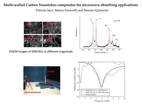
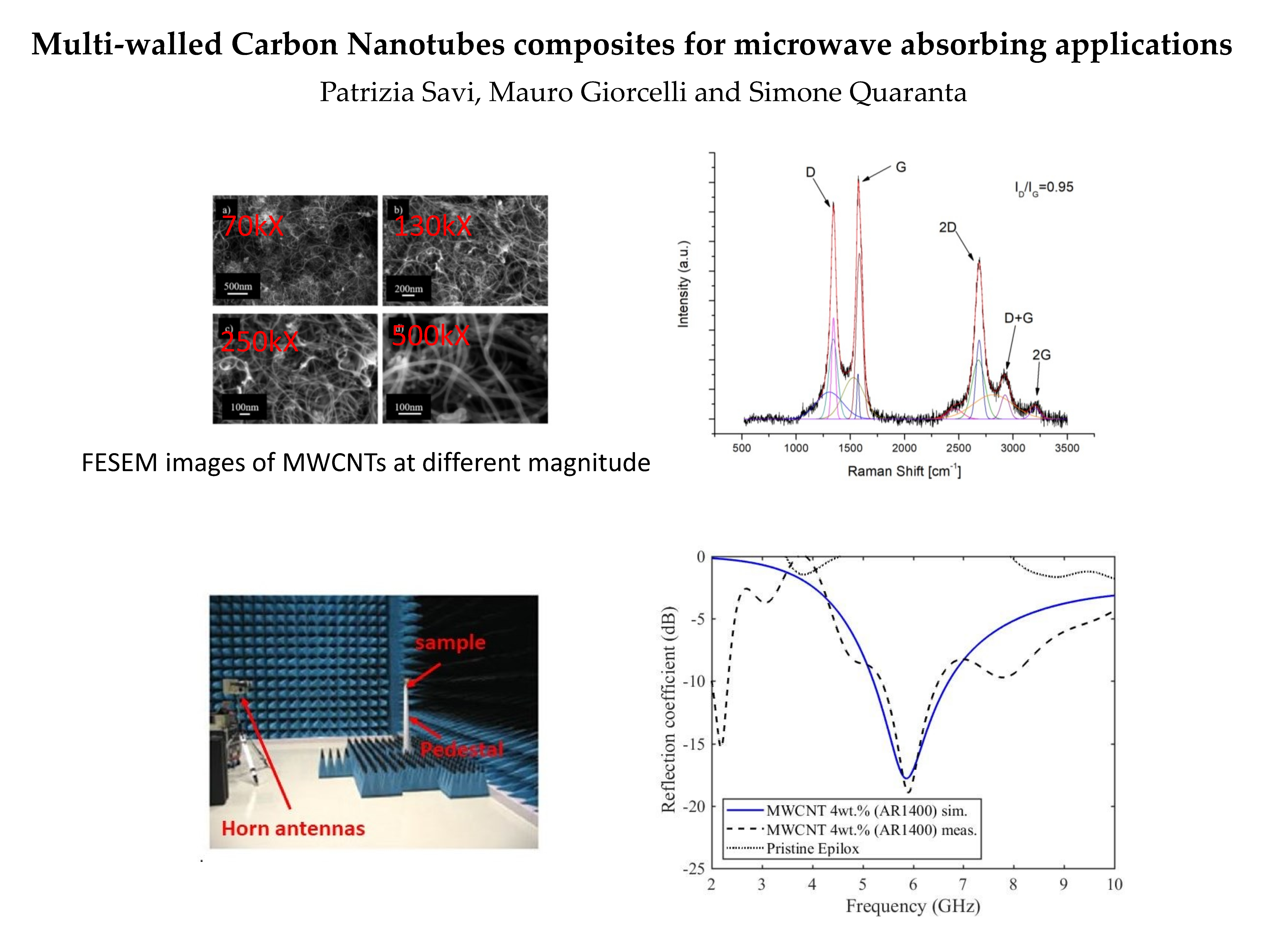
In this paper, multi-wall carbon-nanotube (MWCNT) were dispersed in an epoxy resin polymer matrix in order to prepare a composite.. First, the morphology of the filler was investigated through field emission scanning electron microscopy (FESEM) and Raman spectra. The complex permittivity of pristine polymer matrix and composites with a given (4 wt%) was measured by means of a commercial dielectric probe. Experimental permittivity data were then used to compute the reflection coefficient of one-layer of a given thickness, backed by a metallic plate. Calculations were compared to the measured reflection coefficient of the composite. In addition, the effect of impurities, specific surface area and aspect ratio of the filler was also investigated. Experimental results confirmed the feasibility of epoxy resin-MWCNT (high aspect ratio) composites as microwave absorbers.
2. Materials and Methods
2.1. Materials Characteristics
MWCNTs (Nanothinx, Rio Patras, Greece) were selected for this work. Their characteristics, as declared by the manufacturer, are shown in
Table 1.
MWCNTs were characterized by field emission scanning electron microscopy (FESEM, Zeiss Supra 40, (Oberkochen, Baden-Württemberg, Germany), energy-dispersive x-ray spectroscopy (EDX, Oxford Inca Energy 450, Oxford Instruments Abingdon-on-Thames, UK) and Raman spectroscopy (Renishaw Raman scope, 514.5 nm laser excitation, Wotton-under-Edge, United Kingdom). FESEM analysis was also used to investigate the MWCNTs dispersion in the polymer matrix (Epilox®, Leuna, Germany).
2.2. Sample Preparation and Characterization
Composite samples were prepared from a commercial bi-component thermosetting epoxy resin that acted as dispersing medium for carbon nanotubes. A commercial thermosetting resin (Epilox), produced by Leuna-Harze was used as a polymer matrix. It is a bi-component system formed by a resin and a hardener. Resin (T-19-36/700) is a commercial modified, colorless, low viscosity (650–750 mPa·s at 25 °C) epoxy resin with reduced crystallization tendency and a density of 1.14 g/cm
−3. The chemical composition of Epilox resin T19-36/700 is mainly Bisphenol A (30–60 wt.%), with the addition of crystalline silica (quartz) (1–10 wt.%), Glycidyl ether (1–10 wt.%), inner fillers (160 wt.%). Hardener (H10-31) is a liquid, colorless, low viscosity (400–600 mPa·s at 25 °C) modified cycloaliphatic polyamine epoxy adduct having density 1 g/cm
-3. A single 4 wt% carbon nanotubes loading was employed. 4 wt% choice was predicated on previous studies [
17] concerning the dielectric properties of MWCNT/epoxy resin composites for different MWCNT amounts. Such an investigation had revealed that 4 wt% is a good trade-off between dispersion and dielectric behavior suitable for shielding applications. The sample preparation procedure is reported in [
17,
18]. Briefly, epoxy resin and MWCNTs were mixed by using Ultraturrax for 5 minutes. Hardener was added at the manufacturer-suggested ratio (1:2). Composite solution was poured into a silicon mold and degassed under vacuum in order to remove air bubbles during the polymerization process. Complete polymerization in air took 24 h.
The complex permittivity was measured by a commercial probe (Agilent 85070D) and a network analyzer (E8361A, Keysight Agilent, Santa Rosa, CA, U.S.). A standard calibration short/air/water was performed before each measurement. Several measurements were done on each sample and the average values reported.
2.3. Complex Permittivity Modeling
The complex permittivity of the prepared samples was modeled through a Maxwell-Garnett (MG) formulation [
19]. Such a model can be applied to samples containing a filler volume fraction below the percolation threshold. The MG model was derived from a quasi-static approximation regarding the polarization of the whole sample.
According to the MG model, the effective relative permittivity of a multiphase mixture (isotropic, linear, and with inclusions small compared to the wavelength) can be calculated through the following equation [
19,
20]:
where
is the relative permittivity of the polymer matrix (base dielectric),
is the relative permittivity of the inclusions of type
i,
is the fraction volume occupied by the inclusions of type
i,
is the depolarization factor of the inclusions of type
i,
k is each of the Cartesian coordinates (
x,
y,
z), and
n is the number of inclusion types.
The depolarization factors of canonical and oblate spheroids can be theoretically calculated. For instance, in the case of a needle. Like MWCNTs, the depolarization factors read [
20]:
The electrical permittivity of the inclusions can be estimated from a theoretical model [
19] by assuming that the conductive losses predominate over the dielectric relaxation:
where
is the bulk conductivity of the i-th filler.
2.4. One-Layer Absorber Analysis and Reflection Coefficient Measurement Setup
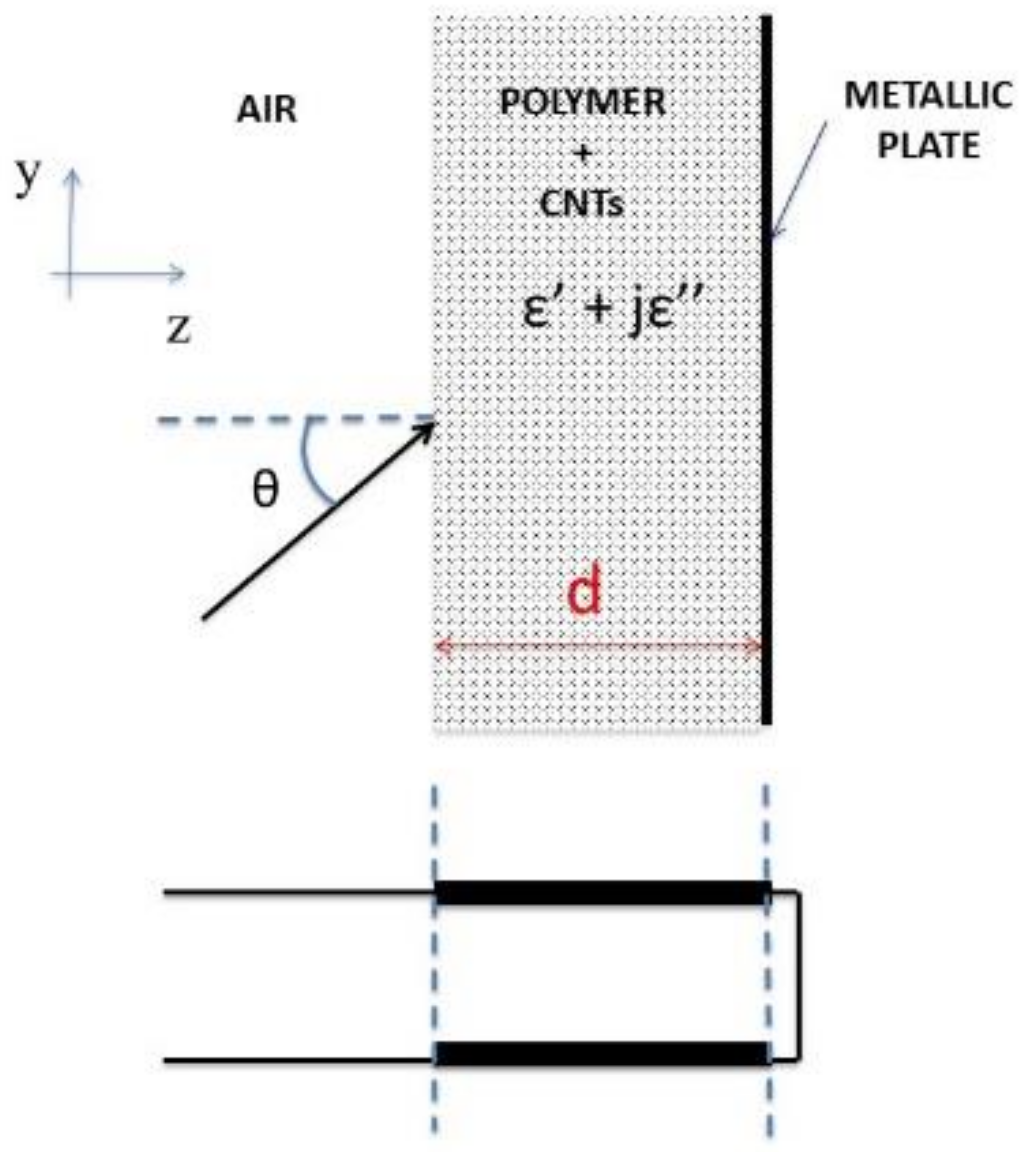
An electromagnetic wave incident on a slab formed by a layer of composite, backed by a metallic plane (perfect electric conductor) as shown in
Figure 1 (top) was considered. When the reflected wave has a half wave phase difference with respect to the incident field, there is destructive interference and the total field vanishes. The geometry of
Figure 1 can be modeled considering a plane wave and a transmission line model (see
Figure 1 bottom) to simulate the reflection coefficient, S
11 [
21]. Z
air and Z
composite are the characteristic impedance of the equivalent lines of air and composites as defined in [
12].
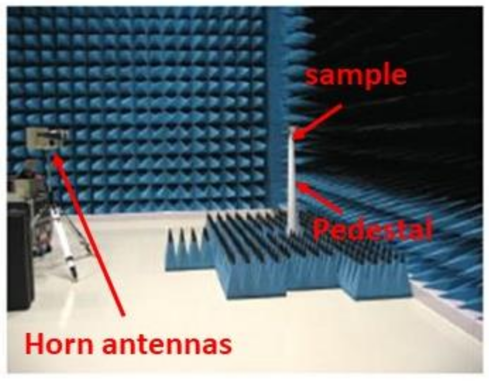
The reflection coefficient of small-sized backed by a metallic plane was measured in an anechoic chamber by means of a network analyzer (Rohde Schwarz, Munich, Germany) and two wide-band horn antennas. The specimen was positioned on a polystyrene cone pedestal. The distance between the pedestal and the two horn antennas was around 5 m. The floor around the pedestal was covered with standard pyramidal absorbers (see
Figure 2). Time gating was performed in order to eliminate multiple reflections.
3. Results
3.1. Filler Morphology Characterization
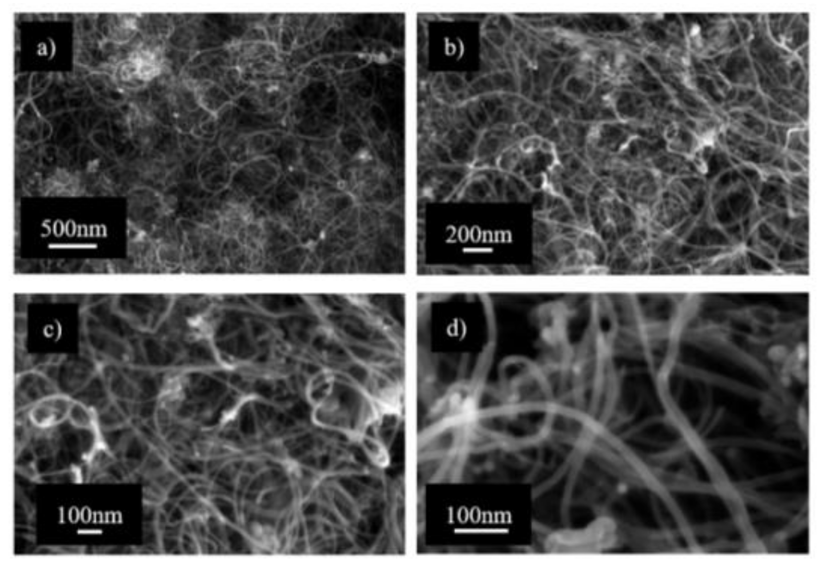
The FESEM images of MWCNTs are reported in
Figure 3. In the inset, a high magnification (500 kX) picture shows that the diameters of MWCNTs are in the range 6–15 nm as stated by the manufacturer. Therefore, the high aspect ratio of the tubes tends to entangle them.
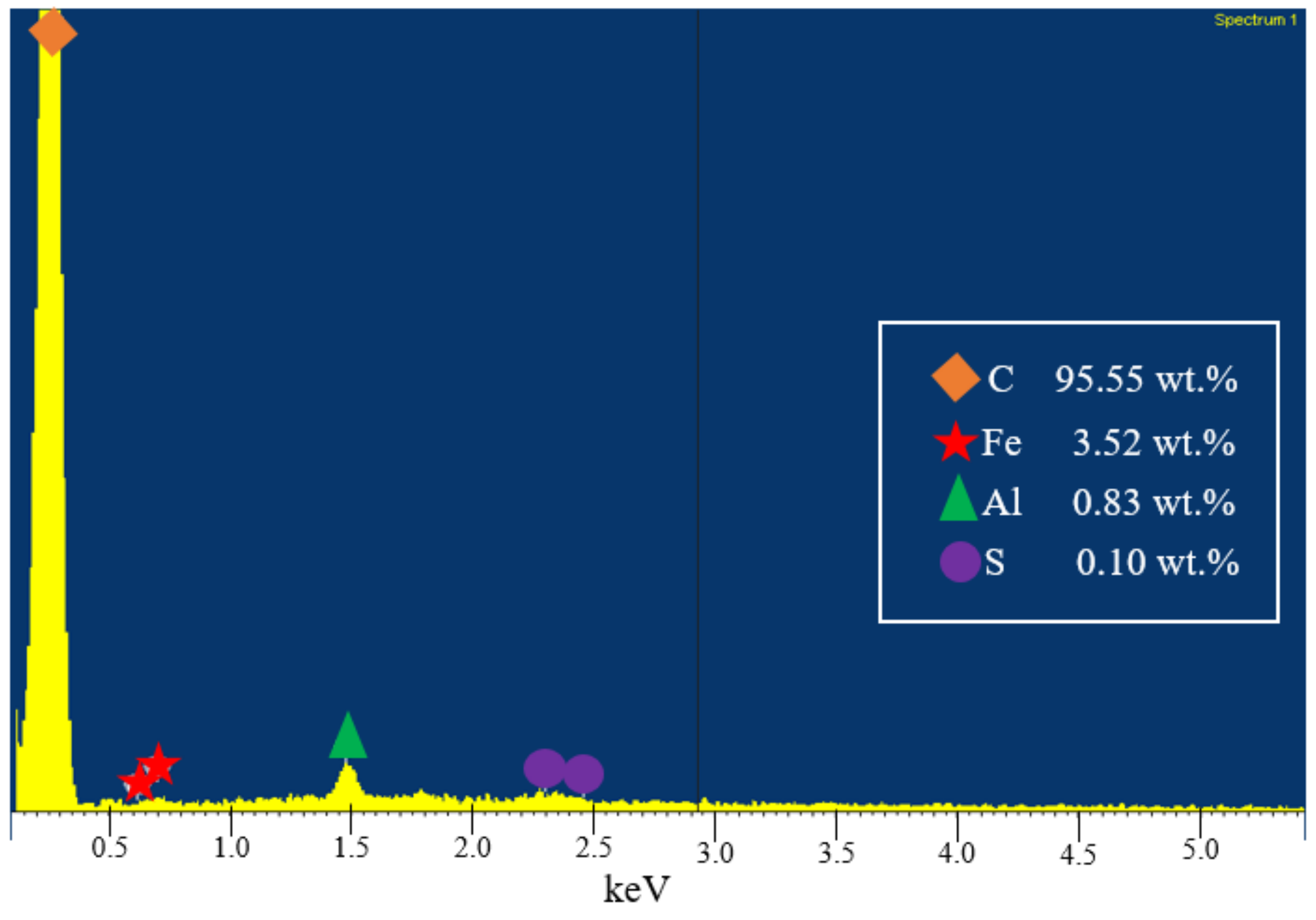
EDX analysis results are reported in
Figure 4. The composition of the MWCNTs is mainly carbon (C, 95.55 wt.%) with the presence of iron catalyst used for MWCNT growth (Fe, 3.52 wt.%). Traces of contaminants such as aluminum (Al, 0.83 wt.%) and sulfur (S, 0.10 wt.%) are also present.
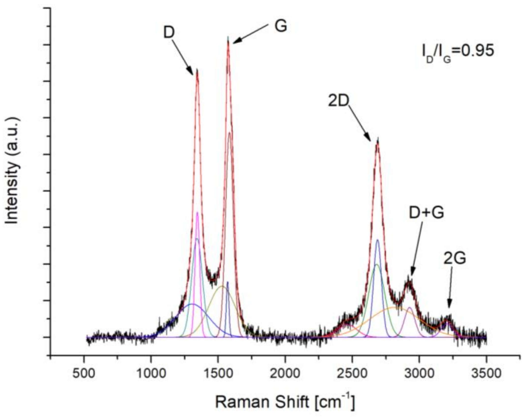
Raman spectra and the associated relative curve fit are displayed in
Figure 5. Usually, the Raman spectrum of the MWCNTs is divided into two main features. The first one, located in the 1000–1700 cm
−1 range, is related to the G and D bands of carbon. In fact, they are the peaks used to estimate defects (D) and graphitization grade (G). The second range (1700–3500 cm
−1) is the second order of the Raman spectrum. D vibration overtone, G’ or 2D band and the second order of D + G and 2G peaks, all belong to this wavenumber range. The calculated ratio (I
D/I
G = 0,95) shows a discrete organization of carbon structure with an intense D peak. The presence of 2D peak verifies the presence of defects [
22].
3.2. Composite Characterization
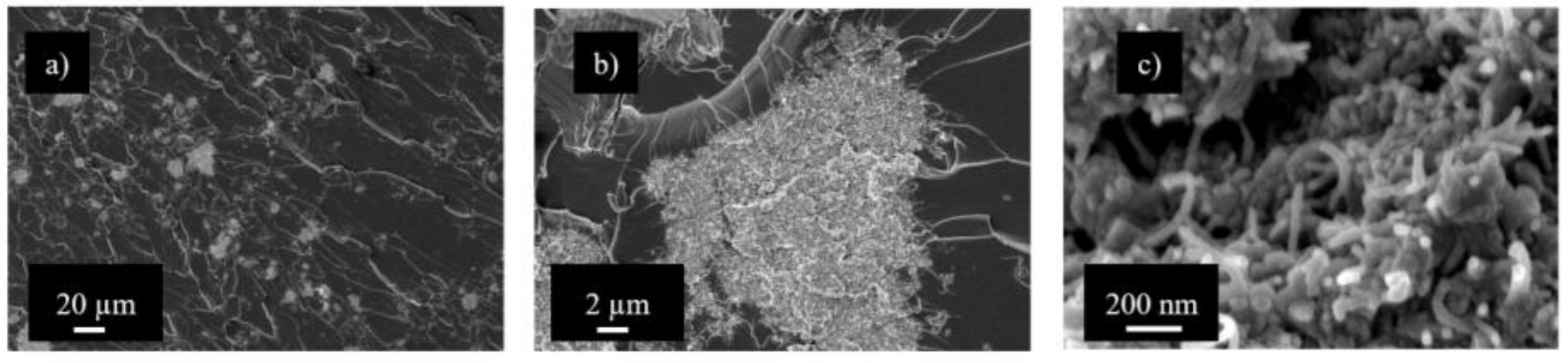
Composite samples were crio-fractured and analyzed at FESEM in order to evaluate the dispersion grade of the MWCNTs. Some significant images are reported in
Figure 6. MWCNTs were not well dispersed into the polymer matrix due to the lack of any surface functionalization. Indeed, some agglomerates are still present like in the original material. Unfortunately, some agglomeration “comes with the territory” regardless of the dispersion method. Agglomerates reduce the electrical conductivity by decreasing the interconnection of conductive structures throughout the polymer matrix. Furthermore, agglomeration affects the dielectric properties of the material by lowering the amount of the filler surface area exposed to the binder. Consequently, the interfacial polarization decreases and both the real and imaginary parts of complex permittivity drop.
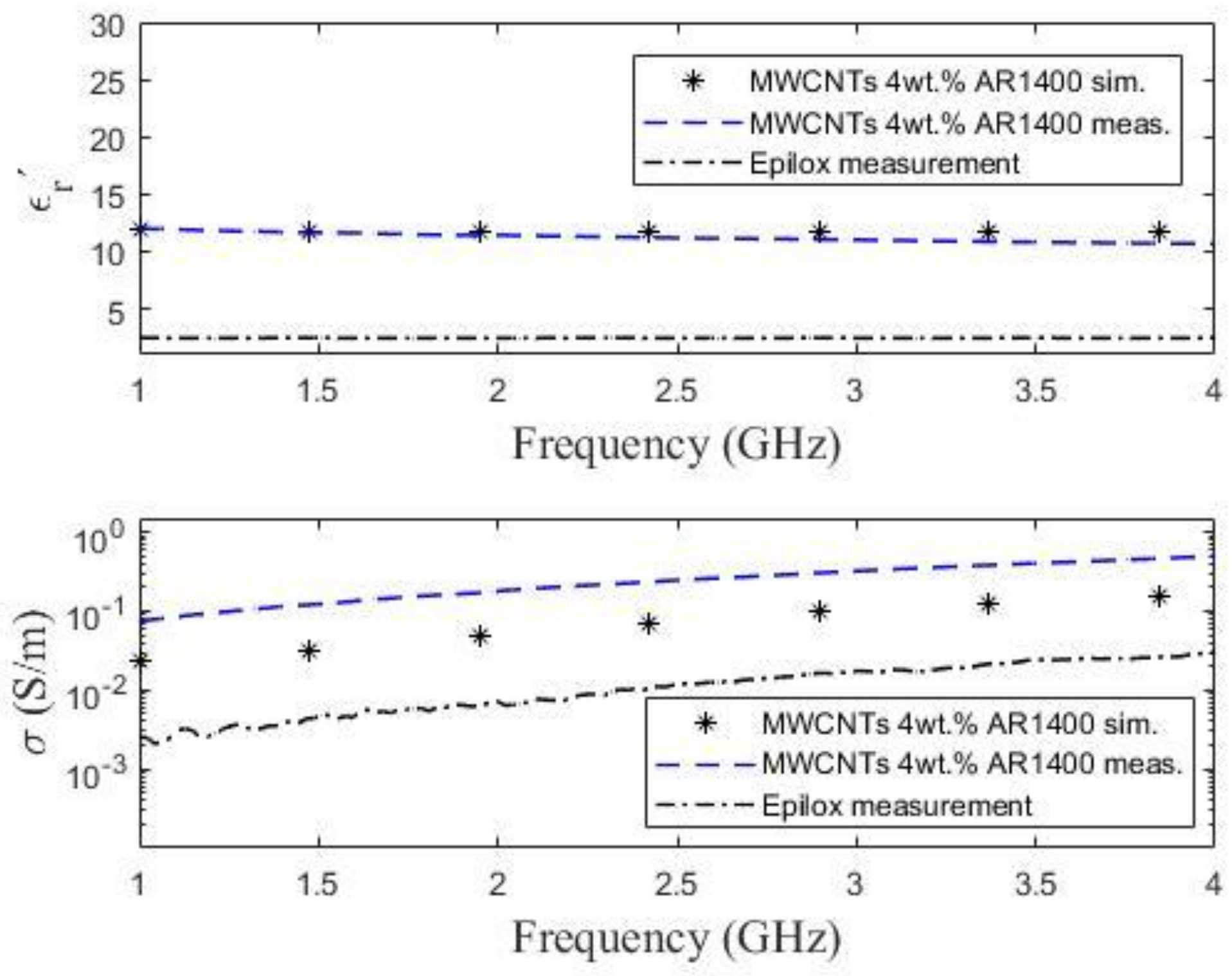
In
Figure 7, the real part of the permittivity and the conductivity of the MWCNTs samples are shown together with the bare resin (Epilox). The measurements are compared to the Maxwell-Garnett model [
19] as detailed in [
23].
As expected, both dielectric constant and the conductivity of the MWCNT-loaded resin are higher than the corresponding parameters of the bare Epilox. In fact, the introduction of carbon nanotubes into the polymer matrix results in the creation of an interfacial polarization component (ε’r increase) and in the formation of a percolative conductive network across the composite (σ increase).
3.3. Analysis of One-Layer Absorber
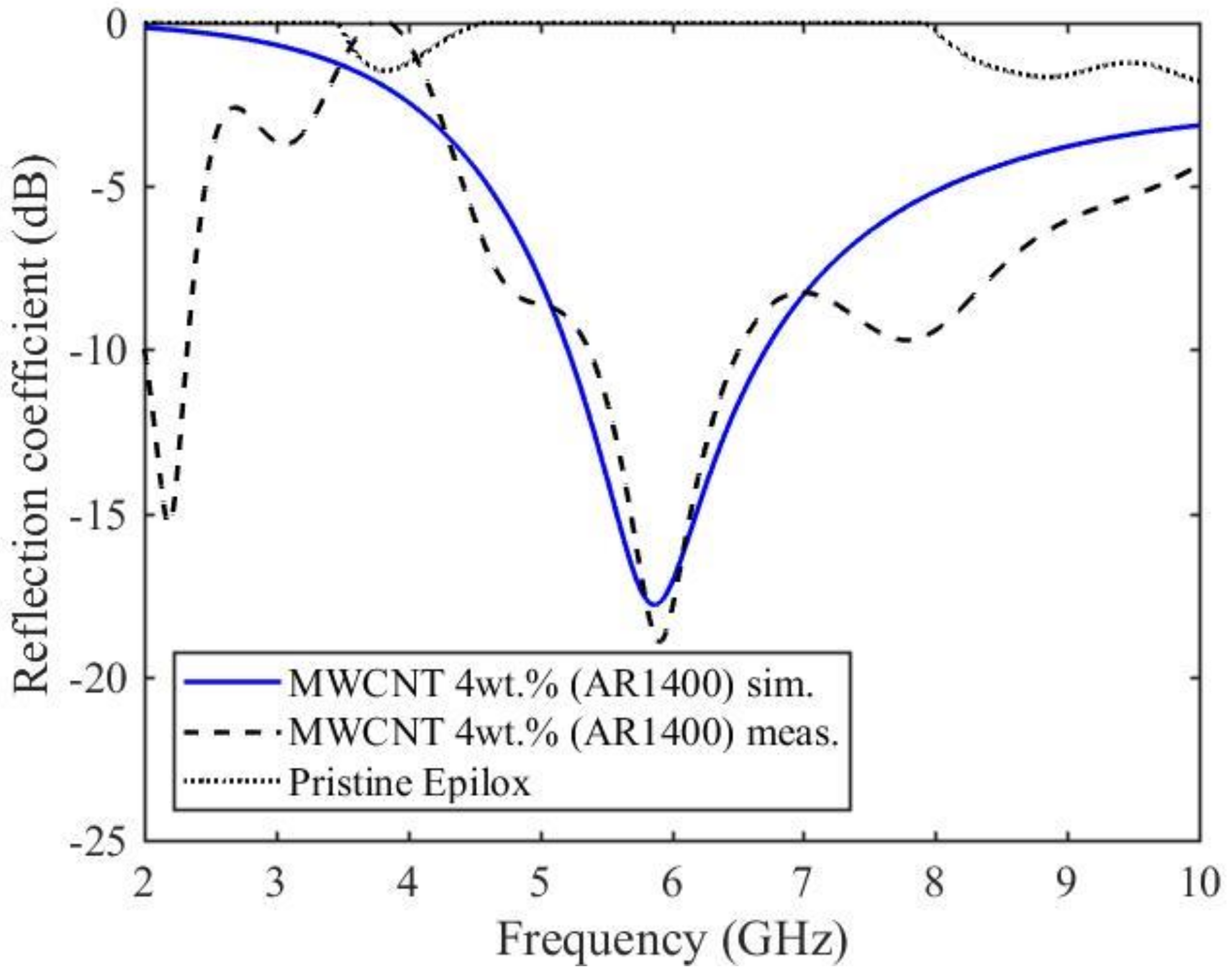
Simulated results obtained considering a one-layer of thickness d = 2 mm and normal incidence are shown in
Figure 8 (solid line) along with the measured data (dashed line) and the bare Epilox (dotted line). Practically no absorption occurs in the case of the resin alone. Obviously, the bare resin cannot benefit from any dielectric loss associated with either interfacial polarization or free-carrier conduction. On the other hand, the increase of the relative permittivity values upon the introduction of the MWCNTs into the polymer matrix produces a minimum in the reflection coefficient because of the increase in the interfacial polarization [
24]. For a 4 wt.%, MWCNT concentration, a peak of −17 dB at 6 GHz is observed.
4. Discussion
As previously stated, microwave absorbing materials (i.e., materials that limit the reflection and transmission) require high dielectric losses (imaginary part of the complex permittivity) in order to convert the energy of the impinging radiation into heat and dissipate it. Needless to say, nanostructured materials such as CNTs have the capability to maximize both terms of the dielectric loss: relaxation and conductivity. A few deductions can be inferred from
Figure 7 and 8. First, the high aspect ratio of the tubes (≈ 1400) in conjunction with their high specific surface area (≈ 300 m
2/g) brings about both a large interfacial polarization relaxing in the microwaves region and a good connectivity of the conductive structure across the composite [
25]. Second, the presence of defects, as emerged from the Raman analysis, may lead to a further increase of the interfacial polarization. Hence, the relaxation of the interfacial polarization can account for the minimum in the reflection coefficient of the composite. Furthermore, a high aspect ratio and a high specific surface area can also cause multiple reflections (scattering), actually entrapping the radiation inside the material. Finally, both the high MWCNT aspect ratio and the relatively high (8 wt.%) content of metallic impurities enhance the composite conductivity and therefore the material losses.
In order to verify such hypotheses, a comparison of the results with a higher load (7 wt%) of structurally different MWCNTs was carried out.
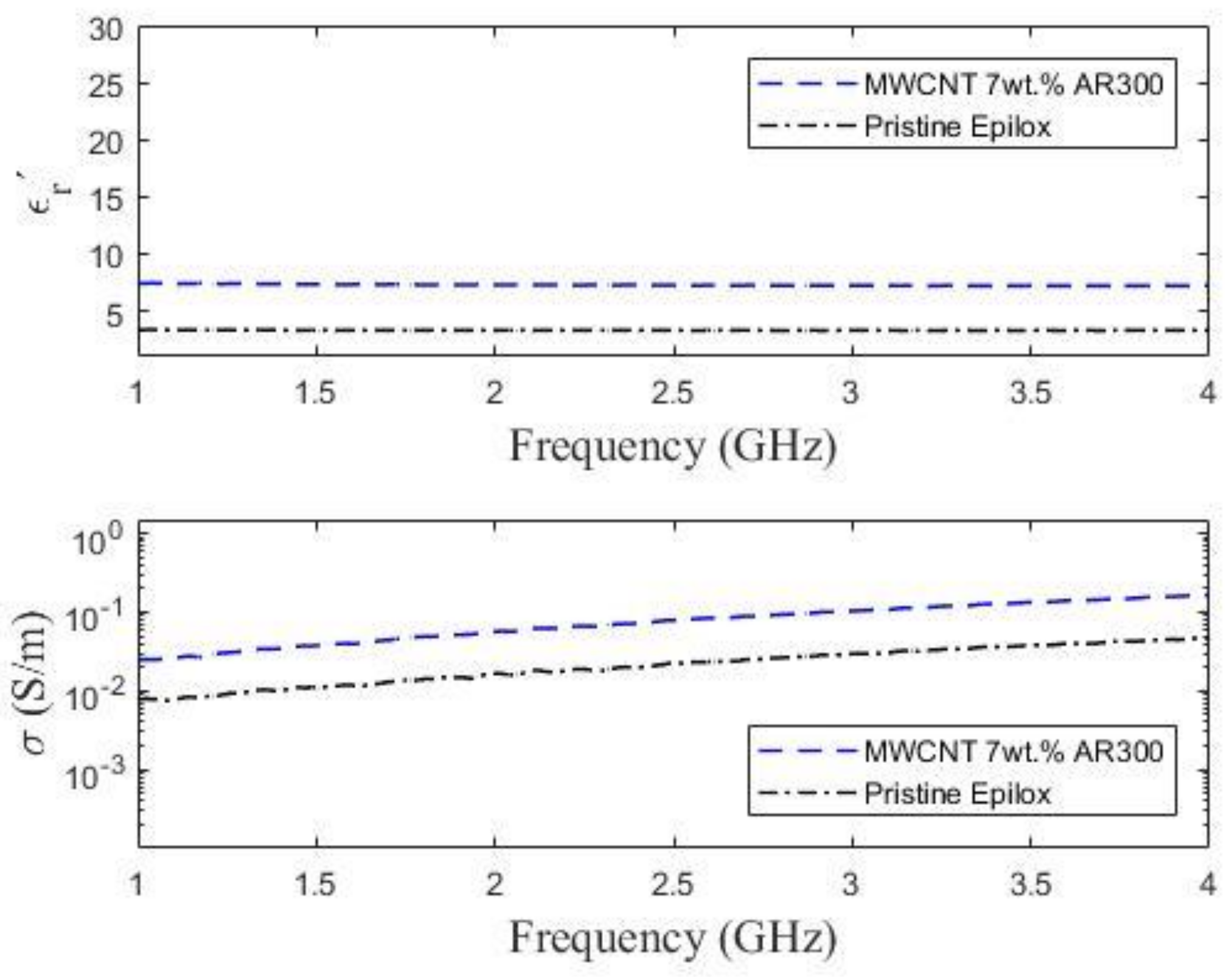
Figure 9 displays the real part of the complex permittivity and the conductivity for an Epilox resin loaded with 7 wt% of MWCNTs possessing the following characteristics: diameter (D) 22–45 nm, length (L) >10 µm, aspect ratio (AR = L/D) ≈ 300, catalyst residue 1.5 wt%, specific surface area (SSA) 200–250 m
2/g. For the sake of simplicity, this sample will be referred to as AR300 while the one employing 4 wt% of high aspect ratio (AR ≈ 1400) MWCNTs will be indicated as AR1400. Although the concentration of MWCNTs in the AR300 composite was almost doubled (i.e., compared to the AR1400), the both the dielectric constant and the conductivity dropped (for instance ε’
r (AR1400) = 12.1 and σ(AR1400) = 0.075 S/m; ε’
r (AR300) = 7.4 and σ (AR300) = 0.025 S/m at 1 GHz).
Thus, the morphological properties of the carbon nanotubes proved to be crucial in determining the dielectric characteristic of the composite. In fact, the lower SSA and aspect ratio of the AR
300 sample inevitably causes a reduction of the interfacial polarization. Consequently, the real component of the complex permittivity decreases. Apparently, also the conductivity seems to be affected by the smaller aspect ratio of the 7 wt% composite. However, the tube length is similar for both kinds of MWCNTs, and other parameters also need to be taken into account. For instance, the two samples differ in the wt% of the metal catalyst residue. Hence, the higher amount of metal particles in the AR1400 composite may also partially account for its higher conductivity. Such morphological (i.e., aspect ratio and specific surface area) and compositional (catalyst residue) features also reflect into the microwave absorption properties of the two materials.
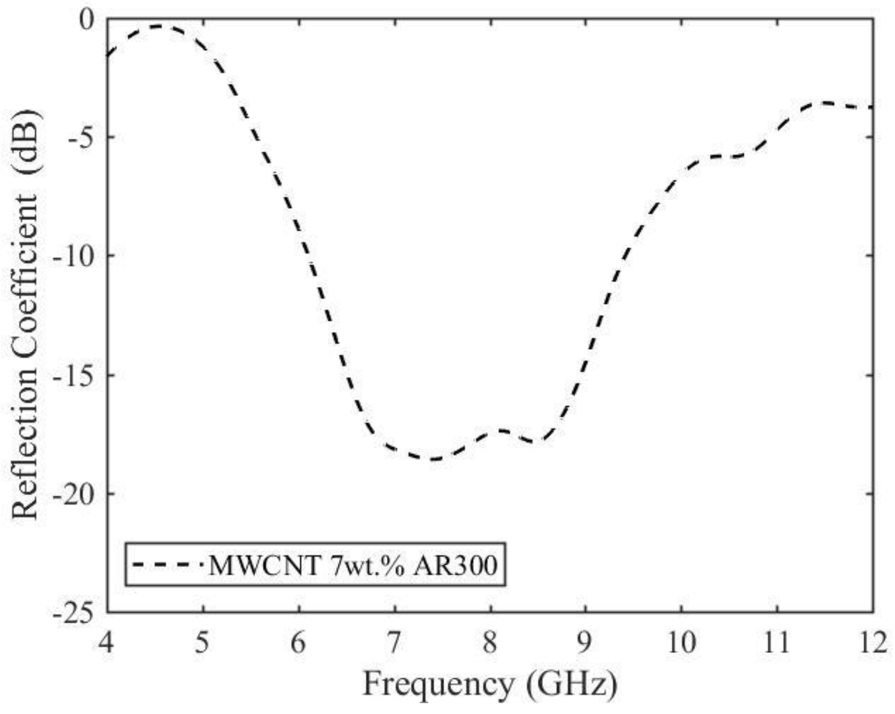
Figure 10 illustrates the reflection coefficient spectrum (for the AR300 composite. Despite the high concentration of carbon nanotubes compared to the AR1400 sample, the lower conductivity and dielectric constant resulted in similar amplitudes of the reflection coefficient.
Thus, by optimizing the aspect ratio, specific surface area, and purity of the MWCNTs in order to achieve large interfacial polarizability and conductivity, it is possible to increase the microwave absorption of MWCNTs and design enhanced materials for EMI shielding.
5. Conclusions
Microwave absorbing nanocomposites based on the MWCNTs (4 wt%)/epoxy resin systems were prepared and characterized. The filler wt% was predicated on previous investigations exploring the relationship between MWCNT concentration, dispersibility, and complex permittivity. Indeed, 4 wt% represents a compromise between filler’s uniform dispersion in the polymer matrix and high real and imaginary permittivity components. In fact, the formation of a conductive network throughout the composite volume allows for energy dissipation by both interfacial polarization and electron transport. Therefore, a 2 mm thick monolayer absorbing material was devised and tested for microwave reflection coefficient. The large interfacial polarization stemming from the MCWCNTs high aspect ratio (≈ 1400), and specific surface area (300 m2/g) resulted in a minimum in composite reflection coefficient at 6 GHz. Such an achievement is in good agreement with simulations. Moreover, dielectric and reflection coefficient measurements performed on epoxy resin composites comprised of morphologically-different MWCNTs demonstrated the aspect ratio, specific surface area, and purity represent dominant factors in determining the microwave absorption properties of the material (rather than the filler concentration).
Author Contributions
P.S. was responsible for permittivity and reflection coefficient measurements, Maxwell-Garnett model and microwave absorber model development and simulation, M.G. was responsible for the FESEM and Raman characterization, S.Q. was responsible for samples preparation; P.S. and S.Q. wrote the paper.
Funding
This research received no external funding
Acknowledgments
The authors would like to thank Nanothinx for supplying MWCNTs, Aamer Khan for help in composite preparation, Salvatore Guastella for FESEM and EDX analysis, and ing. Andrea Delogu, W. Ferrarese, and M. Mwanya (SELEX SE) for the reflection coefficient measurements.
Conflicts of Interest
The authors declare no conflict of interest.
References
- Coleman, J.N.; Khan, U.; Blau, W.J.; Gun’ko, Y.K. Small but strong: A review of the mechanical properties of carbon nanotube–polymer composites. Carbon 2006, 44, 1624–1652. [Google Scholar] [CrossRef]
- Bauhofer, W.; Kovacs, J.Z. A review and analysis of electrical percolation in carbon nanotube polymer composites. Compos. Sci. Technol. 2009, 69, 1486–1498. [Google Scholar] [CrossRef]
- Park, J.H.; Alegaonkar, P.S.; Jeon, S.Y.; Yoo, J.B. Carbon nanotube composite: Dispersion routes and field emission parameters. Compos. Sci. Technol. 2008, 68, 753–759. [Google Scholar] [CrossRef]
- Li, B.; Zhong, W.-H. Review on polymer/graphite nanoplatelet nanocomposites. J. Mater. Sci. 2011, 46, 5595–5614. [Google Scholar] [CrossRef]
- Byrne, M.T.; Guin’Ko, Y.K. Recent advances in research on carbon nanotube–polymer composites. Adv. Mater. 2012, 22, 1672–1688. [Google Scholar] [CrossRef] [PubMed]
- Xu, M.; Du, F.; Ganguli, S.; Roy, A.; Dai, L. Carbon nanotube dry adhesives with temperature-enhanced adhesion over a large temperature range. Nat. Commun. 2016, 7, 13450. [Google Scholar] [CrossRef] [PubMed]
- Yu, S.; Tong, M.N.; Critchlow, G. Use of carbon nanotubes reinforced epoxy as adhesives to join aluminum plates. Mater. Des. 2010, 31 (Suppl. 1), S126–S129. [Google Scholar] [CrossRef]
- Sydlik, S.A.; Lee, J.H.; Walish, J.J.; Thomas, E.L.; Swager, T.M. Epoxy functionalized multi-walled carbon nanotubes for improved adhesives. Carbon 2013, 59, 109–120. [Google Scholar] [CrossRef]
- Koledintseva, M.Y.; Drewniak, J.; DuBroff, R. Modeling of shielding composite materials and structures for microwave frequencies. Prog. Electromagn. Res. B 2009, 15, 197–215. [Google Scholar] [CrossRef]
- Liu, L.; Kong, L.B.; Yin, W.-Y.; Matitsine, S. Characterization of Single- and Multi-walled Carbon Nanotube Composites for Electromagnetic Shielding and Tunable Applications. IEEE Trans. Electromagn. Compat. 2011, 53, 943–949. [Google Scholar] [CrossRef]
- Micheli, D.; Pastore, R.; Apollo, C.; Marchetti, M.; Gradoni, G.; Primiani, V.M.; Moglie, F. Broadband electromagnetic absorbers using carbon nanostructure-based composites. IEEE Trans. Microw. Theory Tech. 2011, 59, 2633–2646. [Google Scholar] [CrossRef]
- Savi, P.; Miscuglio, M.; Giorcelli, M.; Tagliaferro, A. Analysis of microwave absorbing properties of Epoxy MWCNT composites. Prog. Electromagn. Res. Lett. 2014, 44, 63–69. [Google Scholar] [CrossRef]
- De Rosa, I.M.; Sarasini, F.; Sarto, M.S.; Tamburrano, A. EMC Impact of Advanced Carbon Fiber/Carbon Nanotube Reinforced Composites for Next-Generation Aerospace Applications. IEEE Trans. Electromagn. Compat. 2008, 50, 556–563. [Google Scholar] [CrossRef]
- Saib, A.; Bednarz, L.; Daussin, R.; Bailly, C.; Lou, X.; Thomassin, J.M.; Pagnoulle, C.; Detrembleur, C.; Jerome, R.; Huynen, I. Carbon nanotube composites for broadband microwave absorbing materials. IEEE Trans. Microw. Theory Tech. 2010, 1, 2745–2754. [Google Scholar]
- Zinenko, T.L.; Matsushima, A.; Nosich, A.I. Surface-plasmon, grating-mode and slab-mode resonances in THz wave scattering by a graphene strip grating embedded into a dielectric slab. Art. No. 4601809. IEEE J. Sel. Topics Quant. Electron. 2017, 23, 1–9. [Google Scholar] [CrossRef]
- Khushnood, R.A.; Ahmad, S.; Savi, P.; Tulliani, J.-M.; Giorcelli, M.; Ferro, G.A. Improvement in electromagnetic interference shielding effectiveness of cement composites using carbonaceous nano/micro inerts. Constr. Build. Mater. 2015, 85, 208–216. [Google Scholar] [CrossRef]
- Giorcelli, M.; Savi, P.; Yasir, M.; Yahya, M.H.; Tagliaferro, A. Investigation of Epoxy Resin/MWCNT composites behaviour at low frequency. J. Mater. Res. Soft Nanomater. Focus Issue 2015, 30, 101–107. [Google Scholar]
- Giorcelli, M.; Savi, P.; Miscuglio, M.; Yahya, M.H.; Tagliaferro, A. Analysis of MWCNT/epoxy composites at microwave frequency: Reproducibility investigation. Nanoscale Res. Lett. 2014, 9, 1–5. [Google Scholar] [CrossRef] [PubMed]
- Koledintseva, M.; DuBroff, R.E.; Schwartz, R.W. A Maxwell Garnett Model for Dielectric Mixtures Containing Conducting Particles at Optical Frequencies. Prog. Electromagn. Res. 2006, 63, 223–242. [Google Scholar] [CrossRef]
- Sihvola, A.H.; Kong, J.A. Effective permittivity of dielectric mixtures. IEEE Transactions Geosci. Remote Sens. 1988, 26, 420–429. [Google Scholar] [CrossRef]
- Ishimaru, A. Electromagnetic Wave Propagation, Radiation, and Scattering; Prentice Hall: Englewood Cliffs, NJ, USA, 1991. [Google Scholar]
- Dresselhaus, M.S.; Dresselhaus, G.; Saitoc, R.; Joriod, A. Raman spectroscopy of carbon nanotubes. Phys. Rep. 2005, 409, 47–99. [Google Scholar] [CrossRef]
- Mora, N.; Savi, P.; Giorcelli, M.; Rachidi, F. Analysis and Modeling of Epoxy/MWCNT Composites. In Proceedings of the International Conference on Electromagnetics in Advanced Applications (ICEAA2015), Torino, Italy, 7–11 September 2015. [Google Scholar]
- Miscuglio, M.; Yahya, M.H.; Savi, P.; Giorcelli, M.; Tagliaferro, A. RF Characterization of polyer multi-walled carbon nanotube composites. In Proceedings of the IEEE Conference on Antenna measurements & Applications (CAMA), Antibes Juan-les-Pins, France, 16–19 November 2014; pp. 1–4. [Google Scholar]
- Wang, H.; Zhu, D.; Zhou, W.; Fou, L. Electromagnetic and microwave absorbing properties of polyimide nanocomposites at elevated temperature. J. Alloys Compd. 2015, 648, 313–319. [Google Scholar] [CrossRef]
© 2019 by the authors. Licensee MDPI, Basel, Switzerland. This article is an open access article distributed under the terms and conditions of the Creative Commons Attribution (CC BY) license (http://creativecommons.org/licenses/by/4.0/).


