Article

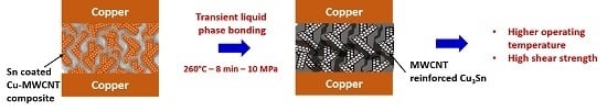
Transient Liquid Phase Bonding of Copper Using Sn Coated Cu MWCNT Composite Powders for Power Electronics

1
Department of Materials Science and Engineering, University of Seoul, Seoul 130-743, Korea
2
Lightweight Materials Technology Center, Gyeongbuk Technopark, Yeongju, Korea
*
Author to whom correspondence should be addressed.
Appl. Sci. 2019, 9(3), 529; https://doi.org/10.3390/app9030529
Submission received: 31 December 2018 / Revised: 28 January 2019 / Accepted: 31 January 2019 / Published: 4 February 2019
(This article belongs to the Special Issue Selected Papers from the NMJ2018)

Abstract

:
In this paper, a novel transient liquid phase bonding material was fabricated by consequent electroless plating of Cu and Sn on a multi-walled carbon nanotube (MWCNT). The resulting Sn-Cu-MWCNT composites were used to join the Cu interconnects at 260 °C. After 8 min of reflow time, a complete transformation of Cu3Sn intermetallic compound (IMC) occurred, leaving a Cu/MWCNT-Cu3Sn/Cu joint capable of withstanding the high operating temperature. Due to flake-like morphology, the Sn-Cu-MWCNT composite particles were well packed with lesser voids. The shear strength of the Cu/Cu3Sn-MWCNT/Cu joint was measured as 35.3 MPa, thus exhibiting the scope for replacing conventional transient liquid phase (TLP) powders in the future.

Graphical Abstract

1. Introduction

As the advancement in the electronic era proceeds, power devices are finding their scope in automotive, aerospace, and electronics industries. In recent years, the incorporation of new semiconductor materials like SiC, GaAs, Si3N4, and AlN in power devices demands stable interconnects with high operating temperatures (>250 °C) [1]. Therefore, the conventional low melting point solders such as Sn-Pb, SnAgCu, and Sn-Bi cannot be used for power electronic devices [2]. Currently, these power devices are interconnected using thermo-compression joining [3], high temperature soldering [4], and nano Ag paste sintering [5]. However, the major drawbacks in these methods are (1) high joining temperature, which enhances the interface diffusion; (2) high applied pressure, which damages the semiconductor substrates; and (3) high manufacturing cost.
An intermetallic compound (IMC) layer bonding technique named transient liquid phase (TLP) bonding surpassed the above difficulties. In this method, a low melting temperature metal is sandwiched and melted between high temperature parent metal to make a joint. The reaction between low temperature metal with the parent metal results in the formation of IMC with a high melting temperature. Devices interconnected using TLP bonding method can withstand an operating temperature higher than the joining temperature [6]. Many successful TLP joints, such as Cu/Sn/Cu [7], Ag/Sn/Ag [8], Ni/Sn/Ni [7], and Cu/Sn-Bi/Cu [9], are well-established. The major limitation in TLP bonding is the longer joining duration and brittle fracture of IMC, which deteriorate the joint stability [6]. Recently, the use of Sn coated Cu powders in TLP joining reduced the joining duration [10]. However, enhancing the strength of Cu-Sn IMC in TLP bonding remains unsolved.
Carbon nanotubes (CNT) [single-walled carbon nanotube (SWCNT) and multi-walled carbon nanotube (MWCNT)] composites are effective in enhancing the electrical, thermal, and mechanical properties of metals and hence exist as potential candidates in electronic packaging [11,12,13,14]. CNTs are used in electrically conductive epoxy resins [12]. Ni coated CNTs are effectively used in solder joints [13], and Cu coated CNTs are used in through-silicon via (TSV) filling [14]. In the present work, Sn coated Cu-MWCNT powders are fabricated by consecutive Cu and Sn electroless plating and employed as interconnected material for TLP joining of Cu. The formation of IMC’s after joining, the strength of the joints, and their fracture surfaces were examined.

2. Materials and Methods

2.1. Electroless Plating of MWCNT

2.1.1. Electroless Plating of Copper on MWCNT

Multi-walled carbon nanotubes (60–100 nm diameter, 1–2 µm) purchased from Tokyo Chemical Industry Co. Ltd. were boiled in 1:3 mixed acid solution of HNO3 and HCl at 100 °C for 10 min and subsequently rinsed with distilled water until the pH approached neutral (pH = 7). The chemicals used in the electroless deposition were purchased from Daejung, Korea. The surface activation of MWCNT was performed using a palladium activation solution. The purpose of surface activation was to incorporate the Pd nuclei on the MWCNT surface, which initiates copper nucleation during coating. The MWCNT was stirred in solution containing 0.055 MF tin II chloride (SnCl2), 0.003 M palladium II chloride (PdCl2), and 0.5 M hydrochloric acid (HCl) for 12 h at 40 °C. The MWCNT were washed with distilled water, rinsed in sodium hypophosphite (NaPO2H2) for 10 minutes, and subsequently washed with distilled water. Copper coated MWCNT were obtained by stirring the surface activated MWCNTs in a copper electroless bath for 1 h. The bath was composed of 0.042M of copper II sulfate pentahydrate (CuSO4 • 5H2O), 0.0029 M of nickel II sulfate heptahydrate (NiSO4 • 7H2O), 0.242 M of sodium hypophosphite (Na2H2PO2 • H2O), 0.060 M of sodium citrate (Na3C6H5O7), 0.51 M of boric acid (H3BO3) with minor poly ethylene glycol (PEG 6000) addition, and few drops of sodium hydroxide were added to maintain a pH of 9. The solution was maintained at 50 °C. The copper coated MWCNT were filtered and washed with distilled water and dried in the oven at 60 °C. After coating, the powders were weighed using analytical balance and the weight gain (δ) percent was calculated [(δ% = ((W2 − W1)/W1) × 100], where W1 is the initial weight of the MWCNT powders and W2 is the weight of the powders after copper coating (grams).

2.1.2. Electroless Plating of Sn on Cu-MWCNT Composite Powders

The tin solution bath composition was adopted from Hu et al. [15]. Stirred in 80 mL of stilled water were 0.2 M thiourea (CH4N2S), 0.0014 M of ethylene diamine tetra acetic acid (EDTA), 0.0038 M of hydroquinone (C6H6O2), 0.2 M of sodium hypophosphite (Na2PO2H2), 0.0042 M of methane sulphonic acid (CH4O3S), and 15 mL/L glycol (CH2OH)2. Separately, 2 g of stannous chloride was mixed in 1mL of HCl. The latter was added to the former solution drop-wise and stirred to obtain a clear solution. The Cu-MWCNT composite powders were added to the Sn electroless plating bath and stirred for 2 h at room temperature. The Sn coated Cu-MWCNT composite powders were filtered, washed subsequently with distilled water, and dried in the oven. The weight of Sn coating was controlled by varying the ratio of Cu-MWCNT powders to stannous chloride in grams. The weight gain percentage after coating was calculated using the formula as described above. The mass percent of Cu and Sn in the coating were maintained at approximately 62% and 38%, respectively. The powders were then characterized using XRD using Cu K-α spectrum with wavelength of 1.5406 A (Bruker AXS GmbH-D8 DISCOVER, Karlsruhe, Germany) and analytical scanning SEM (JEOL JSM-6010PLUS, Tokyo, Japan) attached with energy dispersive spectrometer (EDS).

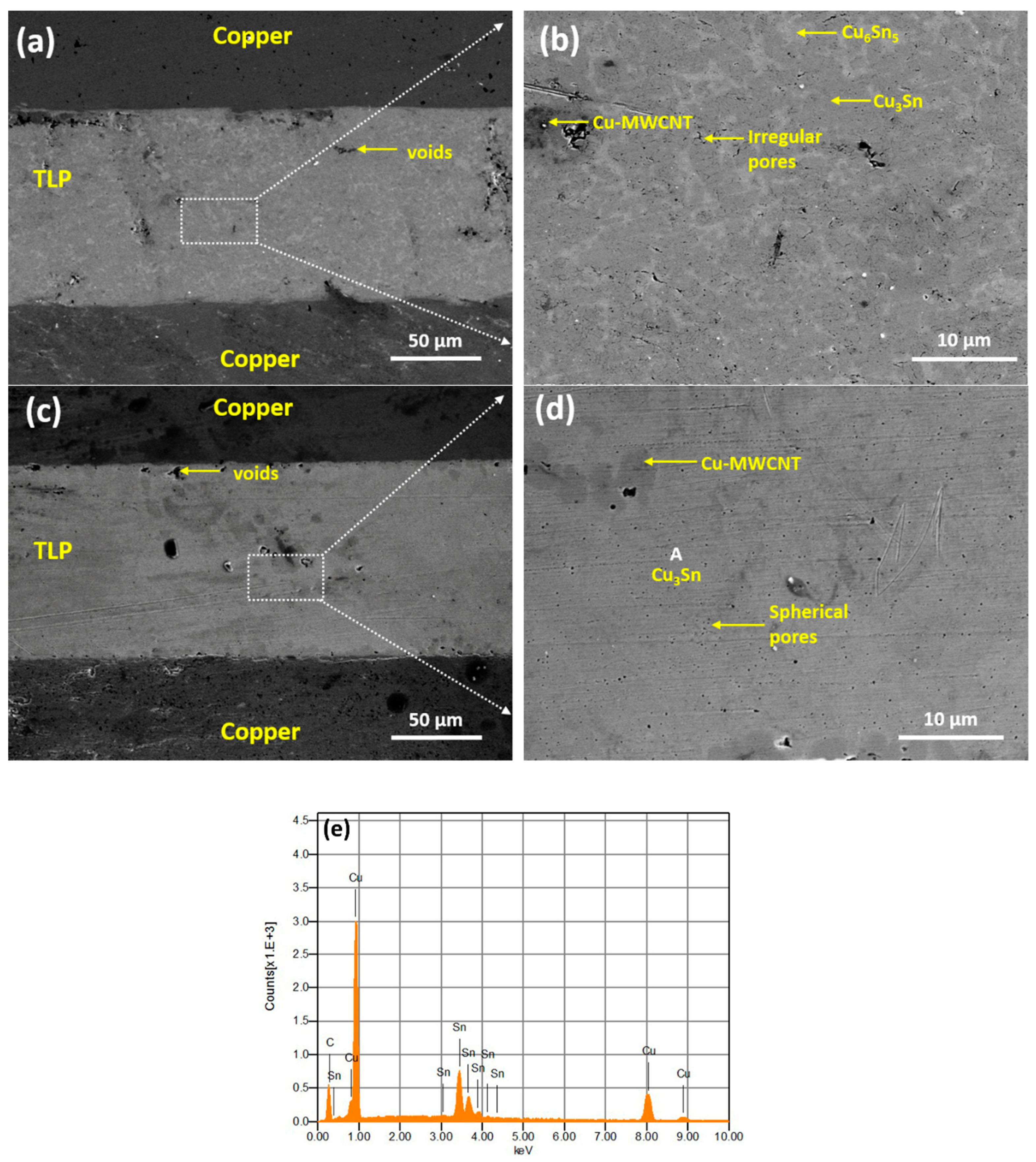
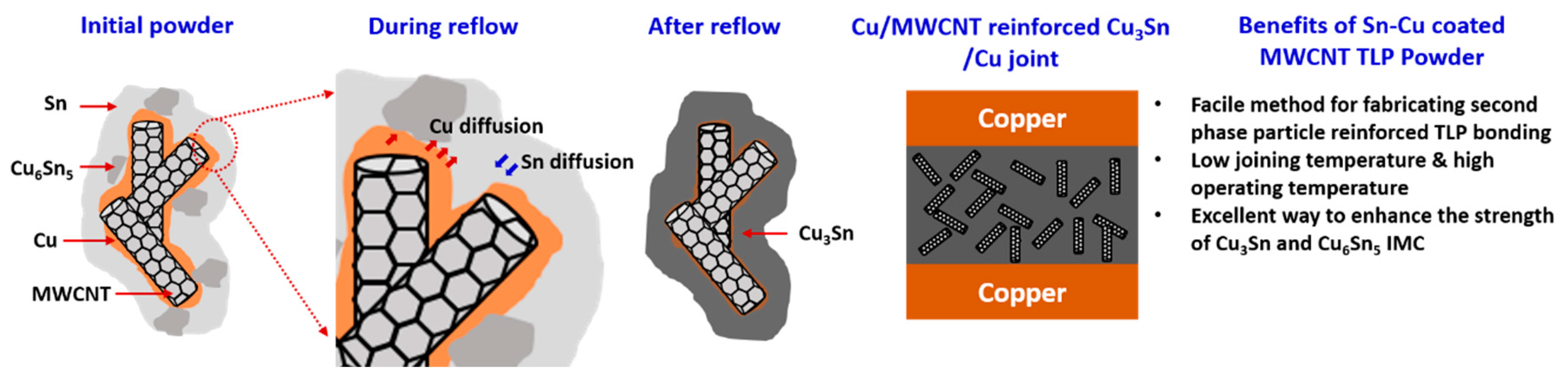
2.2. Transient Liquid Phase Joining

Copper substrates (20 mm × 10 mm × 1 mm) were polished and cleaned in 5% HNO3 to remove any surface impurities. The Sn coated Cu-MWCNT composite powders were mixed with 10 wt% Rosin mildly activated (RMA) type sparkle flux (Senju Metal Industry. Co. Ltd) to form a paste. The paste was printed using 150 µm thick stainless-steel stencil and sandwiched between top and bottom copper substrates. The samples were joined in air at 260 °C for 3, 5, and 8 min at 10 MPa applied pressure. After joining, the samples were cut cross-sectional, ground using 800, 1200, and 2400, grit SiC papers, and polished with diamond paste. The microstructure of the joints was analyzed using SEM and EDS. Shear test samples were fabricated by stencil printing of TLP paste with a thickness of 150 µm on copper substrate with a dimension of 20 mm × 10 mm × 1 mm. Copper die with dimensions of 3 mm × 3 mm × 2 mm were placed on the top of the stencil printed TLP paste and joined with an effective bonding area of 9 mm2. The strength of the joint was tested using shear tester (Rhesca) at the rate of 1mm/min at room temperature.

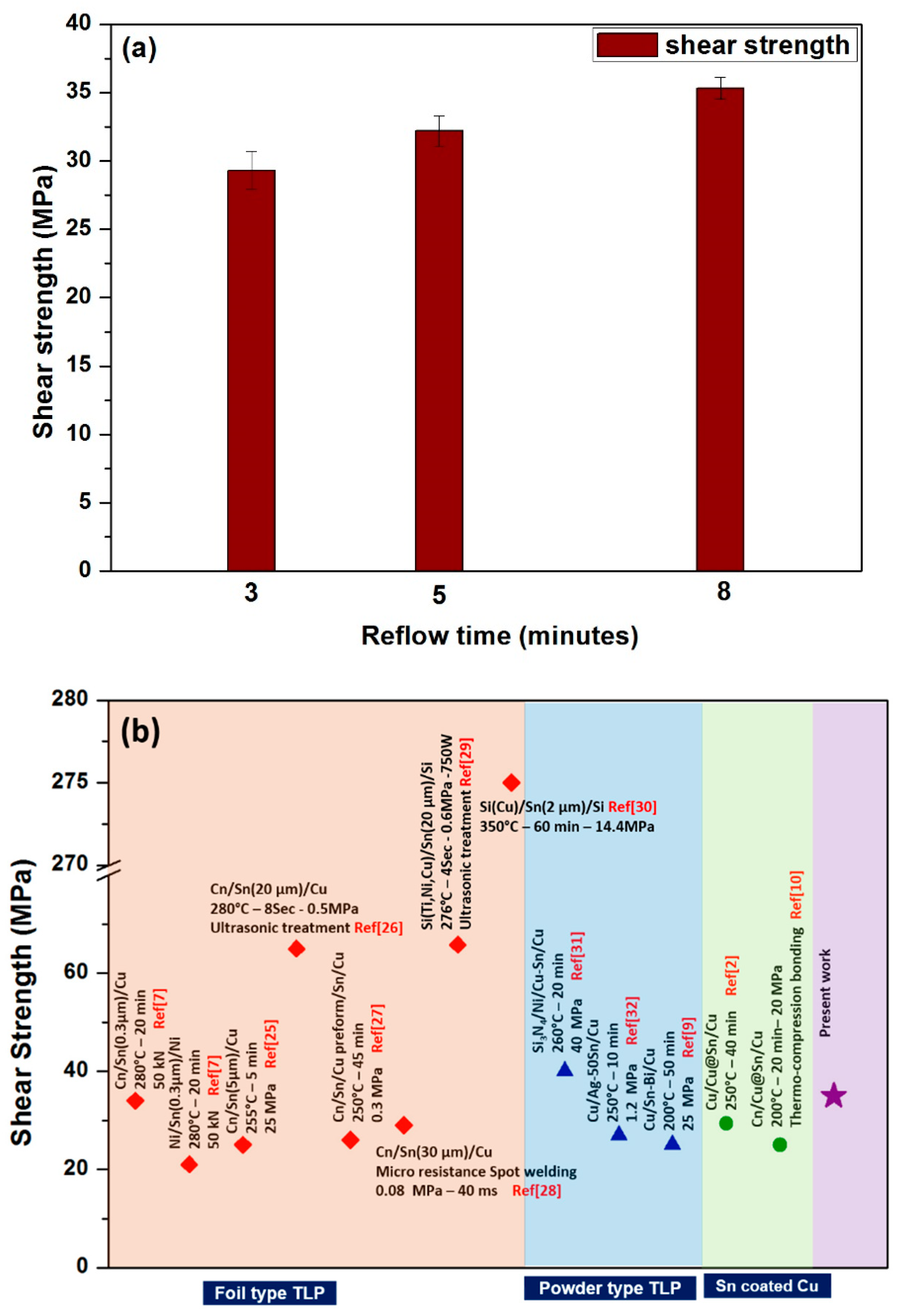
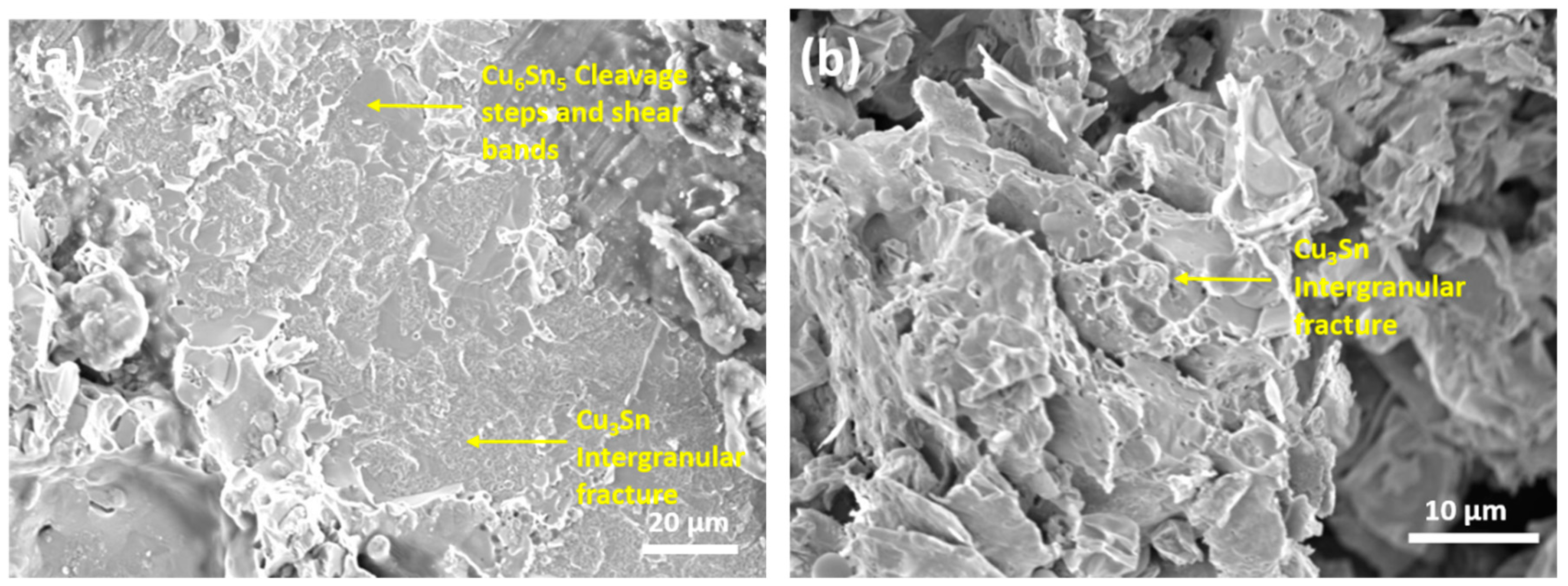
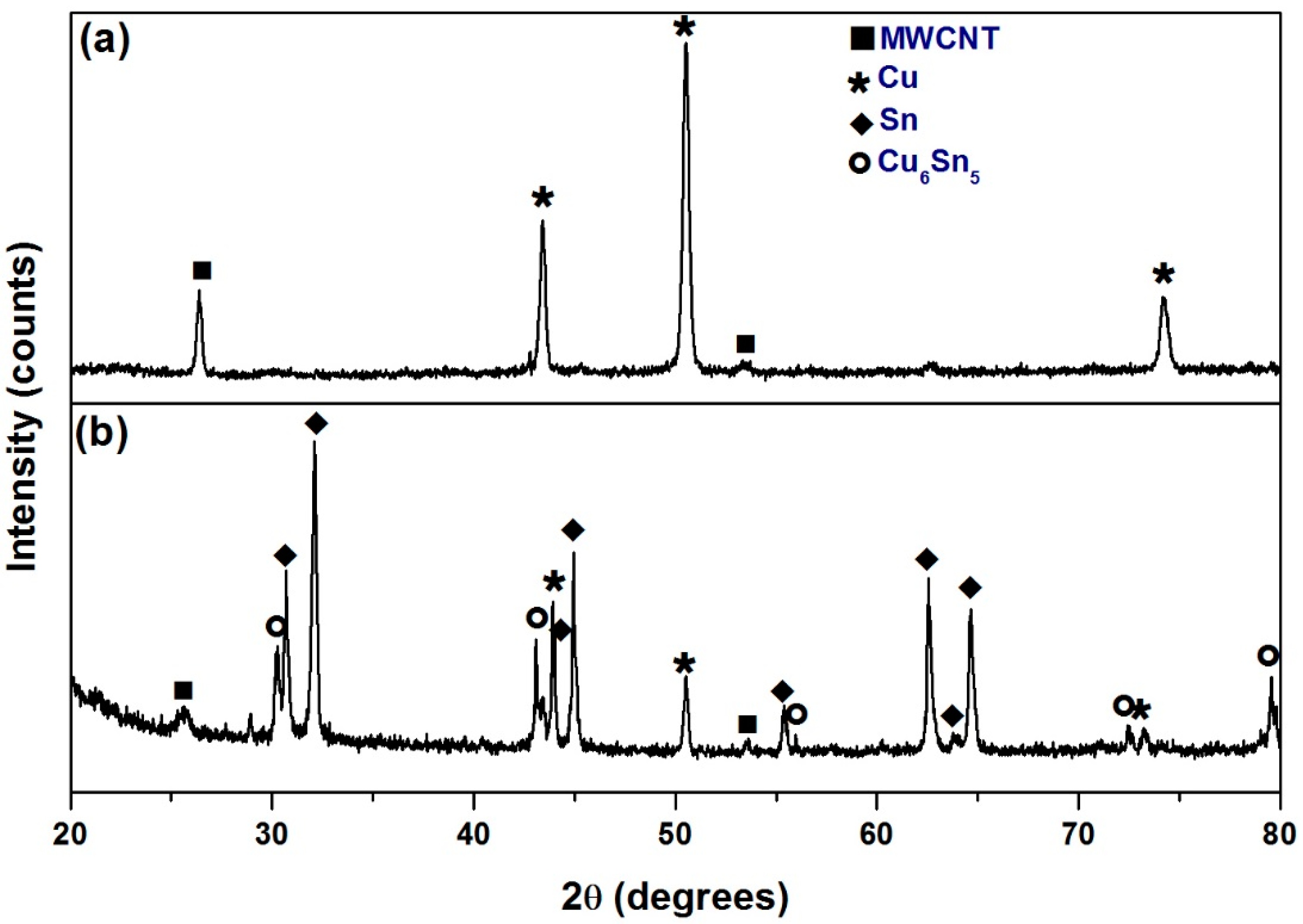
3. Results and Discussions

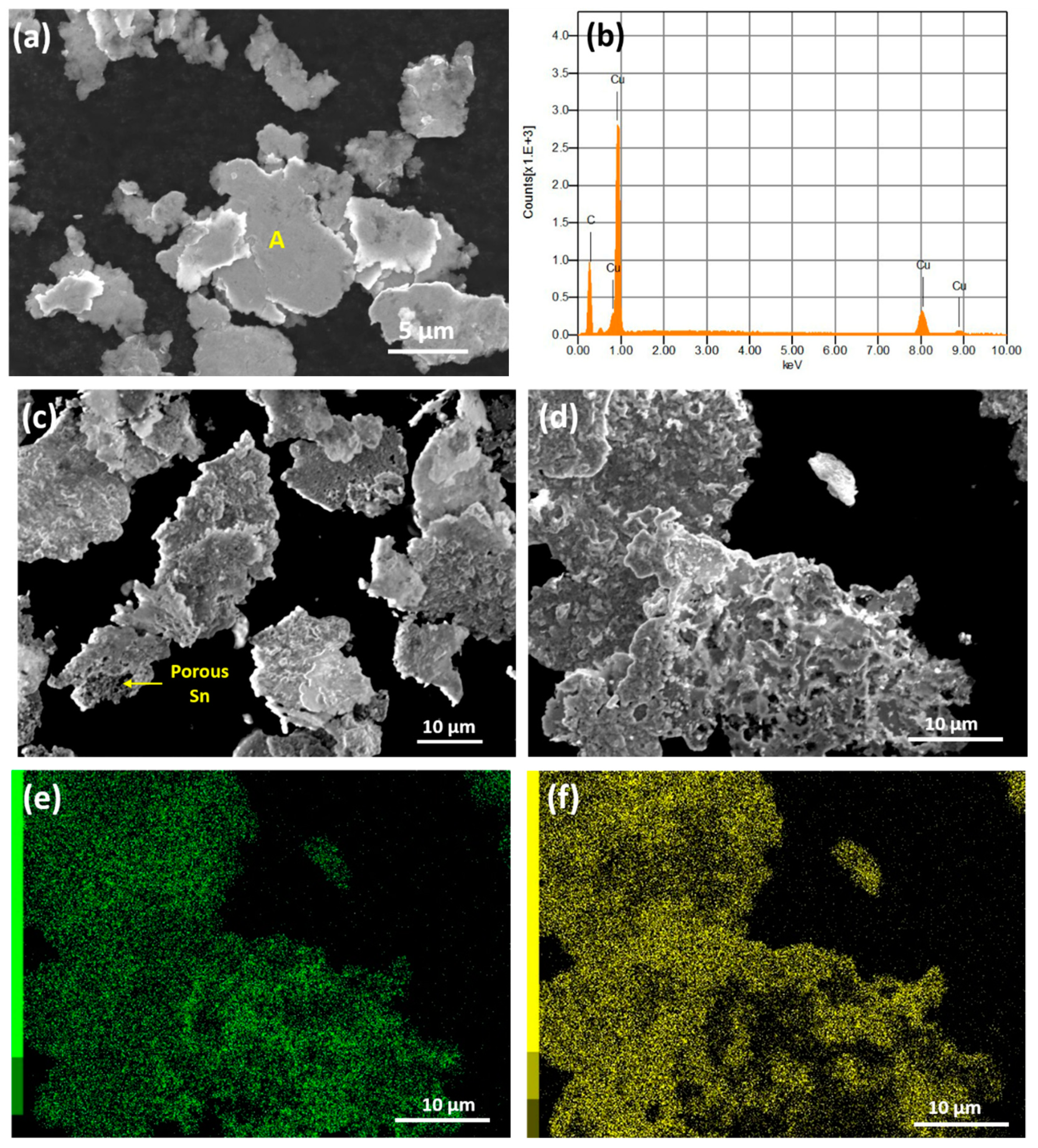
Characterization of Sn-Cu Coated MWCNT

Figure 1a,b shows the XRD analysis of Cu-MWCNT composites and Sn coated Cu-MWCNT composite powders, respectively. The CNT peaks appeared along with the copper peaks in Figure 1a, thus confirming the Cu-MWCNT composite. The XRD of the Sn coated Cu-MWCNT in Figure 1b showed the peaks corresponding to Cu, Sn, and Cu6Sn5 phases. The XRD analysis suggests that few Sn reacted with Cu to form Cu6Sn5 IMC during electroless coating.
Figure 2a–f shows the morphology and elemental analysis of the Cu-MWCNT composite and Sn coated Cu-MWCNT composite powders investigated by SEM and EDS. As seen from Figure 2a, the copper coated morphology of MWCNT were irregular and flake-like, with average particle sizes of 8.4 ± 5 µm when compared to the initial size of 60–100 nm diameter and 1–2 µm length. This could be due to the agglomeration of MWCNTs during copper coating, resulting in the Cu-MWCNT composite. The EDS analysis corresponding to region A [Figure 2a], as shown in Figure 2b, confirms the presence of elements C and Cu in the Cu-MWCNT composite.
Figure 2c,d shows porous coating of Sn on the Cu-MWCNT composite flakes. The average particle size of Cu-MWCNT after Sn coating increased to 21.7 ± 8 µm. Figure 2e,f shows the elemental maps that confirm the coating of Cu and Sn. Due to the irregular morphology of the Cu-MWCNT composite, the Sn coating was not uniform. After Sn coating, few regions were Sn rich, while others were Cu rich, therefore we conclude that a high pressure of 10MPa is required during the TLP process to achieve a good bonding.
The cross-sectional microstructures of the Cu/Sn coated Cu-MWCNT/Cu joint after TLP bonding at 260 °C for 5 min and 8 min are shown in Figure 3a–e. Few pores were observed in the microstructure of the TLP joint reflowed at 260 °C for 8 min when compared to the 5 min sample, as shown in Figure 3a,c.
In the Cu-Sn system, Cu6Sn5 and Cu3Sn were the well-established stable intermetallic phases of the Cu and Sn reaction. Firstly, the planar Cu6Sn5 IMC formed at the Cu/Sn interface according to Equation (1) [16] because the thermodynamic driving force for the formation for Cu6Sn5 was higher than Cu3Sn at 250 °C [17].
6 C u + 5 S n C u 6 S n 5
Cu3Sn IMC formed in the vicinity of copper rich regions either by Equation (2) or by the transformation of Cu6Sn5 IMC as per Equation (3) due to the diffusion of Cu atoms [16].
3 C u + S n C u 3 S n
C u 6 S n 5 + 9 C u 5 C u 3 S n
In a layered Cu-Sn-Cu system with increasing reflow time, planar Cu6Sn5 transformed to a scallop type that grew from both sides until Sn was completely consumed, causing them to ripen and impinge on each other. Meanwhile, Cu3Sn emerged in the Cu/Cu6Sn5 interface and with an increase in reflow time, Cu3Sn continued to grow at the expense of Cu6Sn5 [17]. The formation of Cu-Sn IMC led to a total volume shrinkage of 8.5% [18]. The volume shrinkage was compensated by a decrease in thickness of the Cu/Sn/Cu sandwich, however, at the impingement interface (middle region), volume shrinkage was accompanied by the formation of voids [19]. It was reported that these voids could be controlled by optimizing the experimental parameters, such as applied pressure, reflow time, and interlayer thickness [17,20].
In the case of the Cu-Sn powder TLP system, voids were more prominently subjected to the large difference in diffusivity of Cu and Sn [21]. The inhomogeneity in mixing the Cu and Sn powder further enhanced the void formation due to the presence of residual Sn (excess unreacted Sn) and IMC formation, resulting in volume shrinkage [22]. Sn coated Cu particles proved to be efficient in reducing the diffusion distance of Cu and Sn. However, voids still occurred due to the accommodation of spherical particles (shape factor) [10]. These voids could significantly reduce the shear strength of the joints and weaken the interconnection. With the use of Sn coated Cu-MWCNT composite powders in the present work, the voids at the joints were reduced when compared to the conventional Cu/Sn foil/Cu TLP [23] and Cu/Sn coated Cu/Cu TLP [10]. This could be due to the flake-like morphology of the Sn-Cu-MWCNT composite. Under the applied pressure, Sn-Cu-MWCNT flakes could rearrange themselves, forming a highly dense compact. However, low diffusion among the particles resulted in the irregular shape pores due to incomplete coalescence, as seen in Figure 3b. With increasing reflow time, the pores shape changed from irregular to spherical, as shown in Figure 3d. This showed the driving force for the pores to attain the shape with minimum interface energy, which was only possible through sufficient diffusion time [10]. The high magnification microstructures in Figure 3b showed the presence of a high fraction of Cu3Sn phases (dark grey) along with a few Cu6Sn5 phases (light grey). After eight minutes of bonding time, the microstructure in Figure 3c showed the complete transformation of Cu6Sn5 to Cu3Sn. Composition analysis corresponding to the region A of Figure 3d showed a 3:1 atomic ratio of the elements Cu and Sn, thus confirming the formation of Cu3Sn.
Cu3Sn are highly desirable phases in interconnect applications, as they can withstand an operating temperature up to 676 °C [2]. During the joining process, as the temperature reaches 232 °C, Sn coated on the Cu-MWCNT melts and reacts with copper to form Cu-Sn IMC. At the interface of Sn and Cu-MWCNT, Cu3Sn forms according to Equation (2), whereas in Sn rich regions (surface of Sn coated Cu-MWCNT), Cu diffusion leads to the formation of Cu6Sn, according to Equation (1). This results in Cu3Sn and Cu6Sn5 mixed phases, as observed in Figure 3a,b. With the increase in reflow time, Cu diffusion proceeds and leads to the transformation of Cu6Sn5 to Cu3Sn, as per Equation (3), resulting in the single Cu3Sn phase, as seen in Figure 3c,d. The explained mechanism is schematically illustrated in Figure 4. Moreover, it is reported that that diffusion of Cu is faster in Cu6Sn5 than in Sn [24]. In the present work, the Cu6Sn5 IMC formed during Sn electroless coating on Cu-MWCNT [as detected through XRD in Figure 1b] is considered an added advantage for enhancing Cu diffusion and thereby enhancing the complete transformation of Cu6Sn5 to Cu3Sn.
Figure 5a shows the shear strength of copper to copper joints bonded with Sn coated Cu-MWCNT powders reflowed at 260 °C as a function of bonding time. Initially, for 3 min of bonding time, the shear strength was 29.4 MPa. By increasing the bonding time to 5 and 8 min, the shear strength increased to 32.2 and 35.3 MPa. The shear strength obtained for the Sn coated Cu-MWCNT reflowed at 8 min was well within the upper limit of conventional TLP joints, as shown in Figure 5b [7,9,10,25,26,27,28,29,30,31,32]. Microstructural aspects such as the type and dispersion of second phase particles play an important role in the mechanical property of the joint. In the present work, a high shear strength is attributed to the inherent strength and stiffness of CNT and the reduction of voids. After the complete transformation of Cu6Sn5 to Cu3Sn, the joint microstructure is similar to the three dimensional MWCNT network reinforced Cu3Sn IMC composite. In brittle materials, CNTs are reported to enhance the strength and toughness in three ways: (1) crack deflection at the CNT/matrix interface; (2) crack bridging; and (3) pull out of CNT [33]. Similar work by Han et al [34] reported that the addition of 0.05 wt% Ni coated CNT in SAC solder enhanced the shear strength of the joint by 29%.
Figure 6a,b shows the fracture surface of copper to copper joints bonded with Sn coated Cu-MWCNT powders reflowed at 260 °C for 5 and 8 min, respectively. In the 5 min reflow sample, cleavage steps and shear bands were observed along the Cu6Sn5 IMC networks, while an intergranular brittle fracture occurred in the Cu3Sn, which indicated the presence of a fine grain structure. Reportedly, Cu6Sn5 (140 MPam−1/2) have lower fracture toughness than Cu3Sn (170 MPam−1/2) [35]. Thus, propagation of cracks is easier in Cu6Sn5 compared to Cu3Sn. In the 8 min reflow sample, an intergranular brittle fracture occurred along the Cu3Sn IMC, accompanied by a few dimples in the Cu3Sn particles. This could have been due to the pull out of the MWCNT networks in the Cu3Sn during shear.
The present approach for fabricating MWCNT integrated Cu3Sn IMC bonding overcomes the problems associated with the joining duration and compositional inhomogeneity during conventional powder mixing and has a good potential to enhance the shear strength of Cu-Sn IMC. Shear strength obtained in the present work was well within the upper limit of the reported values [Figure 5b]. Therefore, further work is required to optimize Cu and Sn coating parameters and the bonding conditions to improve the shear strength of the joint.

4. Conclusions

In this study, a novel approach was adopted to achieve MWCNT integrated Cu-Sn IMC interconnection in TLP bonding. Sn and Cu were successfully coated on MWCNT through electroless plating. The Cu to Cu TLP joint was achieved using Sn coated Cu-MWCNT composite powders at 260 °C with10 MPa applied pressure. Reflow time of 8 min was sufficient to form graphene integrated Cu3Sn IMC. Unlike conventional TLP bonding using powders, large voids were not observed. The Cu/MWCNT-Cu3Sn/Cu joints showed shear strength of 35.3 MPa, which is higher than conventional Cu/Sn foil/Cu joints. A fracture occurred along the intergranular regions of Cu3Sn IMC, whereas fine dimples were present along the transgranular region due to pull out of MWCNT.

Author Contributions

Conceptualization, experiments, and paper writing—S.H.R.; D.H.J. and W.S.J. helped in shear testing; J.P.J. supervised and directed the research.

Acknowledgements

This work was supported by the Korea Institute of Energy Technology Evaluation and Planning (KETEP) and the Ministry of Trade, Industry & Energy (MOTIE) of the Republic of Korea (No. 20172020109280).

Conflicts of Interest

The authors declare no conflict of interest.

References

  1. Liu, X.; Nishikawa, H. Microstructure of Transient Liquid Phase Sintering Joint by Sn-Coated Cu Particles for High Temperature Packaging. In Proceedings of the IMAPS 2015 Orlando—48th Annual International Symposium on Microelectronics, Orlando, FL, USA, 26–29 October 2015; pp. 000449–000452. [Google Scholar]
  2. Hu, T.; Chen, H.; Li, M. Die attach materials with high remelting temperatures created by bonding Cu@Sn micro particles at lower temperatures. Mater. Des. 2016, 108, 383–390. [Google Scholar] [CrossRef]
  3. Fan, J.; Tan, C.S. Low temperature wafer-level metal thermos-compression bonding technology for 3D integration. In Metallurgy: Advances in Materials and Processes; IntechOpen Ltd.: London, UK, 2012; pp. 71–94. [Google Scholar]
  4. Chidambaram, V.; Hattel, J.; Hald, J. High-temperature lead free solder alternatives. Microelectron. Eng. 2011, 88, 981–989. [Google Scholar] [CrossRef]
  5. Yan, J.F.; Zou, G.S.; Wu, A.P. Pressure less bonding process using Ag nanoparticles paste for flexible electronics packaging. Scr. Mater. 2012, 66, 582–585. [Google Scholar] [CrossRef]
  6. Li, Z.; Li, M.; Xiao, Y.; Wang, C. Ultra rapid formation of homogeneous Cu6Sn5 and Cu3Sn intermetallic compound joints at room temperature using ultrasonic waves. Ultrason Sonochem. 2014, 21, 924–929. [Google Scholar] [CrossRef] [PubMed]
  7. Chu, K.; Sohn, Y.; Moon, C. A comparative study of Cn/Sn/Cu and Ni/Sn/Ni solder joints for low temperature stable transient liquid phase bonding. Scr. Mater. 2015, 109, 113–117. [Google Scholar] [CrossRef]
  8. Li, J.F.; Agyakwa, J.F.; Johnson, C.M. Kinetics of Ag3Sn growth in Ag–Sn–Ag system during transient liquid phase soldering process. Acta Mater. 2010, 58, 3429–3443. [Google Scholar] [CrossRef]
  9. Mokhtari, O.; Nishikawa, H. The shear strength of transient liquid phase bonded Sn–Bi solder joint with added Cu particles. Adv. Powder Technol. 2016, 27, 1000–1005. [Google Scholar] [CrossRef]
  10. Liu, X.; He, S.; Nishikawa, H. Low temperature solid-state bonding using Sn-coated Cu particles for high temperature die attach. J. Alloys Compd. 2017, 695, 2165–2172. [Google Scholar] [CrossRef]
  11. Aryasomayajula, L.; Wolter, K.J. Carbon nanotube composites for electronic packaging applications: A review. J. Nanotechnol. 2013, 2013, 296517. [Google Scholar] [CrossRef]
  12. Bal, S.; Samal, S.S. Carbon nanotube reinforced polymer composites—A state of the art. Bull. Mater. Sci. 2007, 30, 379–386. [Google Scholar] [CrossRef]
  13. Nai, S.M.L.; Wei, J.; Gupta, M. Effect of carbon nanotubes on the shear strength and electrical resistivity of a lead-free solder. J. Electron. Mater. 2008, 37, 515–522. [Google Scholar] [CrossRef]
  14. Kreupl, F.; Graham, A.P.; Liebau, M.; Duesberg, G.S.; Seidel, R.; Unger, E. Carbon nanotubes for interconnect applications. In Proceedings of the IEEE International Electron Devices Meeting (IEDM ’04), San Francisco, CA, USA, 13–15 December 2004; pp. 683–686. [Google Scholar]
  15. Hu, T.; Chen, H.T.; Wang, C.Q.; Huang, M.S.; Zhao, F.F. Study of electroless Sn coated Cu microparticles and their application as a high temperature thermal interface material. Surf. Coat. Technol. 2017, 319, 230–240. [Google Scholar] [CrossRef]
  16. Mookam, N.; Tunthawiroon, P.; Kanlayasiri, K. Effects of Copper content in Sn based solder on the intermetallic phase formation and growth during soldering. IOP Conf. Ser. Mater. Sci. Eng. 2018, 361, 012008. [Google Scholar] [CrossRef]
  17. Yao, P.; Li, X.; Liang, X.; Yu, B. Investigation of soldering process and interfacial microstructure evolution for the formation of full Cu3Sn joints in electronic packaging. Mater. Sci. Semicond. Process. 2017, 58, 39–50. [Google Scholar] [CrossRef]
  18. Kumar, S.; Handwerker, C.A.; Dayananda, M.A. Intrinsic and interdiffusion in Cu–Sn system. J. Phase Equilib. Diff. 2011, 32, 309–319. [Google Scholar] [CrossRef]
  19. Chuang, H.Y.; Yu, J.J.; Kuo, M.S.; Tong, H.M.; Kao, C.R. Elimination of voids in reactions between Ni and Sn: a novel effect of solver. Scr. Mater. 2012, 66, 171–174. [Google Scholar] [CrossRef]
  20. Bosco, N.S.; Zok, F.W. Critical interlayer thickness for transient liquid phase bonding in the Cu-Sn system. Acta Mater. 2004, 52, 2965–2972. [Google Scholar] [CrossRef]
  21. Gao, F.; Qiu, J.M. calculating the diffusivity of Cu and Sn in Cu3Sn Intermetallic by molecular dynamic simulation. Mater Lett. 2012, 73, 92–94. [Google Scholar] [CrossRef]
  22. Bao, Y.; Wu, A.; Shao, H.; Zhao, Y.; Zou, G. Effect of powders on microstructures and mechanical properties for Sn–Ag transient liquid phase bonding in air. J. Mater. Sci. Mater. Electron. 2018, 29, 10246–10257. [Google Scholar] [CrossRef]
  23. Lee, B.S.; Hyun, S.K.; Yoon, J.W. Cu-Sn and Ni-Sn transient liquid phase bonding for die attach technology applications in high temperature power electronics packaging. J. Mater. Sci. Mater. Electron. 2017, 28, 7827–7833. [Google Scholar] [CrossRef]
  24. Chiu, W.L.; Liu, C.M.; Haung, Y.S.; Chen, C. formation of plate like channels in Cu6Sn5 and Cu3Sn Intermetallic compounds during transient liquid reaction of Cu/Sn/Cu structures. Mater. Lett. 2016, 164, 5–8. [Google Scholar] [CrossRef]
  25. Brincker, M.; Sohl, S.; Eisele, R.; Popok, V.N. Strength and reliability of low temperature transient liquid phase bonded Cu-Sn-Cu interconnects. Microelectron. Reliab. 2017, 76–77, 378–382. [Google Scholar] [CrossRef]
  26. Zhou, H.Y.; Liu, J.H.; Li, Z.L.; Song, X.G.; Zhao, Y.X.; Niu, H.W.; Tian, H.; Dong, H.J.; Feng, J.C. A Comparative Study on the Microstructure and Mechanical Properties of Cu6Sn5 and Cu3Sn Joints Formed by TLP Soldering With/Without the Assistance of Ultrasonic Waves. Metall. Mater. Trans. A 2018, 49, 2739–2749. [Google Scholar] [CrossRef]
  27. Shao, H.; Wu, A.; Bao, Y.; Zhao, Y.; Zou, G.; Liu, L. Novel transient liquid phase bonding through capillary action for high temperature power devices packaging. Mater. Sci. Eng. A 2018, 724, 231–238. [Google Scholar] [CrossRef]
  28. Liu, B.; Tian, Y.; Wang, C.; An, R.; Liu, Y. Extremely fast formation of Cu3Sn intermetallic compounds in Cu/Sn/Cu system via a micro-resistance spot welding process. J. Alloys Compd. 2016, 687, 667–673. [Google Scholar] [CrossRef]
  29. Li, M.; Li, Z.; Xiao, Y.; Wang, C. Rapid formation of Cu/Cu3Sn/Cu joints using ultrasonic bonding processes at ambient temperature. Appl. Phys. Lett. 2013, 102, 094104. [Google Scholar] [CrossRef]
  30. Rautiainan, A.; Xu, H.; Österlund, E.; Li, J.; Vuorinen, V.; Krockel, M.P. Microstructural characterization and mechanical performance of Wafer-Level SLID bonded Au-Sn and Cu-Sn seal rings for MEMS encapsulation. J. Electron. Mater. 2015, 44, 4533–4548. [Google Scholar] [CrossRef]
  31. Lang, F.; Yamaguchi, H.; Nakagawa, H.; Sato, H. Thermally Stable Bonding of SiC Devices with Ceramic Substrates: Transient Liquid Phase Sintering Using Cu/Sn Powders. J. Electrochem. Soc. 2013, 160, 315–319. [Google Scholar] [CrossRef]
  32. Sharif, A.; Gan, C.L.; Chen, Z. Transient liquid phase Ag-based solder technology for high-temperature packaging applications. J. Alloys Compd. 2014, 587, 365–368. [Google Scholar] [CrossRef]
  33. Xia, Z.; Riester, L.; Curtin, W.A.; Li, H.; Sheldon, B.W.; Liang, J.; Chang, B.; Xu, J.M. Direct observation of toughening mechanisms in carbon nano tube ceramic matrix composites. Acta Mater. 2004, 52, 931–944. [Google Scholar] [CrossRef]
  34. Han, Y.D.; Jing, H.Y.; Nai, S.M.L.; Xu, L.Y.; Tan, C.M.; Wei, J. Interfacial reaction and shear strength of Ni-coated carbon nano tubes reinforced Sn-Ag-Cu solder joints during thermal cycling. Intermetallics 2012, 31, 72–78. [Google Scholar] [CrossRef]
  35. Lee, H.T.; Chen, M.H.; Jao, H.M.; Liao, L.T. Influence of interfacial intermetallic compound on fracture behavior of solder joints. Mater. Sci. Eng. A 2003, 358, 134–141. [Google Scholar] [CrossRef]
Figure 1. XRD analysis of (a) Cu-MWCNT (multi-walled carbon nanotube) composite; (b) Sn coated MWCNT composite.
Applsci 09 00529 g001
Figure 2. SEM analysis of powders (a) Cu-MWCNT composite; (b) energy dispersive spectrometer (EDS) analysis of point A; (c) and (d) Sn coated Cu-MWCNT composite; (e) and (f) EDS elemental mapping of Cu and Sn, respectively.
Applsci 09 00529 g002
Figure 3. Cross-sectional SEM microstructure of Cu/Sn-Cu-MWCNT/Cu transient liquid phase (TLP) joint at 260 °C. (a) Low and (b) high magnification image of TLP bonding joint at 5 min; (c) and (d) low and high magnification image of TLP bonding joint at 8 min respectively; (e) EDS analysis corresponding to point A.
Applsci 09 00529 g003
Figure 4. Schematic illustrating the mechanism of Cu3Sn-MWCNT formation during TLP bonding.
Applsci 09 00529 g004
Figure 5. (a) Shear strength of Cu/Sn-Cu-MWCNT/Cu TLP bonding joint at 260 °C as a function of reflow time; (b) Comparison of the shear strength data in the present work with the literature.
Applsci 09 00529 g005
Figure 6. Fracture surfaces of the Cu/Sn-Cu-MWCNT/Cu joint for different reflow times (a) 5 min and (b) 8 min.
Applsci 09 00529 g006

