Abstract
Nowadays, the modified nonlocal strain gradient theory provides a mathematically well-posed and technically reliable methodology to assess scale effects in inflected nano-structures. Such an approach is extended in this paper to investigate the extensional behavior of nano-rods. The considered integral elasticity model, involving axial force and strain fields, is conveniently shown to be equivalent to a nonlocal differential problem equipped with constitutive boundary conditions. Unlike treatments in the literature, no higher-order boundary conditions are required to close the nonlocal problem. Closed-form solutions of elastic nano-rods under selected loadings and kinematic boundary conditions are provided. As an innovative implication, Young’s moduli of Single-Walled Carbon Nanotubes (SWCNT) weare assessed and compared with predictions of Molecular Dynamics (MD). New benchmarks for numerical analyses were also detected.
1. Introduction
Components of Nano-Electro-Mechanical-Systems (NEMS), such as sensors and actuators, are usually modeled as nano-rods and nano-beams. It is well known that methods of local continuum mechanics cannot be adopted for such elements. Molecular Dynamics (MD) simulations are time-consuming and micro/nano-scaled experiments are usually difficult to implement. Hence, nonlocal continuum models have been developed for predicting the size-dependent mechanical behavior of nano-structures.
In the framework of nonlocal elasticity, Eringen’s strain-driven differential model [1] has been widely adopted in the literature (see, e.g., [2,3,4,5,6]). It is worth noting that recent papers on the strain-driven nonlocal model [7,8,9,10] prove that, if the bending field is expressed as convolution of elastic curvature with an averaging kernel assuming an exponential expression, a solution of this problem exists only if the bending field satisfies constitutive boundary conditions. Accordingly, it is shown in [11] that the nonlocal elastostatic problem is ill-posed in all cases of applicative interest, as acknowledged in the literature (see, e.g., [12,13,14,15,16,17,18]). A modified version of the Eringen integral model is proposed in [19] and has been recently applied to inflected nanobeams in [20].
The gradient elasticity theory [21] assumes that a material at the nano-scale is modeled via gradient terms. Many works investigate the small-scale effects on the static and dynamic behaviors of rods, beams and plates and the effect of stiffness enhancement has been often reported in these strain gradient models (see, e.g., [22,23,24,25,26]).
Recently, the Eringen’s integral law [1] has been combined with the strain gradient elasticity in [27] to formulate a higher-order nonlocal theory, thus collecting nonlocal theory and strain gradient theory into a single model.
Using such a model, many contributions have been provided to model the size-dependent behavior of nano-rods and beams (see, e.g., [28,29,30,31,32,33,34,35]) and plates [36,37].
The procedure consists in considering the integral nonlocal gradient method for structural problems defined on bounded domains equivalent to a differential law of higher-order than the one of the classical local problem. Therefore, additional non-classical suitable boundary conditions must be added to solve the nonlocal strain gradient elastostatic problem.
To solve the problem, different choices have been followed in the literature. Two usual choices consist in imposing higher-order boundary conditions pertaining to the strain gradient theory, of kinematic type [38] or static type [39]. It is worth noting that the structural behavior is greatly influenced by such choices.
The nonlocal strain gradient theory with higher-order boundary conditions has been recently adopted in [40] to study nano-rods in tension. The closed-form solutions for predicting the axial displacement and the variation of the Young’s modulus have been derived for four different nano-rods differing by the choice of the higher-order boundary conditions. In particular, for each nano-rod, the nonlocal parameters have been set to match the variation of the Young’s modulus obtained by the MD simulations.
The choice of the higher-order boundary conditions is disputed in the literature and is considered an open question (see, e.g., [41]). In the context of nano-beams subjected to flexure, a recent contribution [42] provides a definite solution to this issue. In fact, the non-classical boundary conditions to be imposed to solve the elastostatic problem of nonlocal strain gradient inflected nano-beams are given by constitutive boundary conditions (CBC) that naturally follow from the nonlocal strain gradient integral model. The consistent nonlocal strain gradient strategy has been successfully applied to free vibrations of nano-beams in [43].
In the present paper, the structural behavior of nano-rods in tension is formulated in the framework of the modified nonlocal strain gradient (NSG) theory. The expressions of the CBC for nano-rods are explicitly provided and it is shown that no unmotivated higher-order boundary conditions have to be prescribed to solve the nonlocal structural problem.
In addition, the variation of the Young’s modulus provided by MD simulations is recovered based on the NSG model for nano-rods developed in the present paper. In particular, carbon nanotubes are effectively described by NSG nano-rods with the usual boundary conditions, that is clamped at the one end and with a tensile force at the other end. As illustrated in Appendix A, the same result is obtained if a doubly-clamped nano-rod with an imposed axial displacement at one end is considered.
Finally, numerical analyses are presented as benchmark examples for applications and experimental tests on nonlocal nano-rods.
2. Modified Nonlocal Strain Gradient Law for Rods
Let us consider a functionally graded (FG) straight nano-rod of length L, the x-coordinate is taken along the length of the nano-rod with the y-coordinate along the thickness and the z-coordinate along the width of the nano-rod. The local Young’s modulus E of the FG nano-rod continuously changes in the thickness direction y, so that the Young’s elastic modulus at the point y is and the elastic area is , being the nano-rod cross-section.
In the modified nonlocal strain gradient (NSG) model for FG nano-rods, the axial force N is defined in terms of elastic axial strain and of its derivative is [27]
The smoothing kernels and depend on two non-dimensional nonlocal parameters and . The scale parameter , characteristic of the strain gradient elasticity [21], was subsequently introduced in [27] to make dimensionally homogeneous the convolutions in Equation (1) and to describe the importance of higher-order strain gradient fields.
Following [27,38], we consider that the nonlocal parameters are coincident, i.e., , and the kernels and are coincident with the bi-exponential averaging function given by
being the characteristic length of Eringen nonlocal elasticity. The kernel (Equation (2)) fulfills positivity, symmetry, normalization and impulsivity [42].
Introducing the following fields
the modified nonlocal strain gradient elastic law (Equation (1)) can be rewritten as
As proven in the next proposition, the modified nonlocal strain gradient integral relation (Equation (4)) for FG nano-rods is equivalent to a suitable differential law with constitutive boundary conditions.
Proposition 1 (Constitutive equivalence for FG nano-rods).
Proof.
Since the bi-exponential averaging function is given by
a direct evaluation provides the first derivative of the convolutions (Equation (3))
The second derivative of the convolutions (Equation (3)) follows from Equation (9) using Equation (3) to get
Subtracting the third derivative of Equation (9) from Equation (9), it turns out to be
so that, recalling Equation (5) and rearranging the terms, we have
and Equation (6) is recovered.
The CBC in Equation (7) can be recovered as follows.
Using Equation (9), Equation (5) can be rewritten in the form
and using Equations (9) and (7), the first derivative of Equation (5) becomes
The CBC (Equation (7)) of modified nonlocal strain gradient nano-rods follows by evaluating Equations (13) and (14) at nano-rod boundary points and . In fact, we have at
so that Equation (15) provides the relations
and the CBC in Equation (7) is recovered. Analogously, setting in Equation (14), we get
so that Equation (17) provides the relations
and the CBC in Equation (7) is recovered. Conversely, sufficient condition can be inferred from the uniqueness of the solution of Equation (6) consequent to the fact that the associated homogeneous equations
admit only the trivial solution under the homogeneous boundary conditions
for (19) and for (19) respectively. □
3. Elastic Equilibrium Problem
Let us consider a FG nano-rod subject to a distributed axial load per unit length in the interval and to concentrated axial forces at the end cross-sections and .
Differential condition of equilibrium can be written as
with the boundary conditions at and
The axial displacement at the abscissa x along the nano-rod axis is denoted by and the kinematically compatible axial strain has the form
In the sequel, elastic and kinematically compatible strains are assumed to be coincident.
Exact solutions according to the proposed modified nonlocal strain gradient (NSG) model for FG nano-rods can be performed by the following steps.
- Step 1: Solve the equilibrium Equation (22) to get the expression of the axial force
- Step 2: Solve the second-order differential Equation (6) in the formobtaining the expression of the elastic axial strain of the nano-rod in terms of three integration constants (, , and ) to be determined.
- Step 3: Solve the first-order differential in Equation (23) in terms of the axial displacement u of the nano-rod to get the expression of u in terms of four integration constants (, , , and ) to be determined.
- Step 4: Determine the four integration constants (, , , and ) by imposing the two CBC given by Equation (7) in terms of the axial displacement uand the two classical boundary conditions at the nano-rod end points and by specifying
It is worth noting that, in statically determinate rods, the axial force N can be obtained by Equation (24) by imposing the classical static boundary conditions.
4. Closed-Form Solutions for FG Nano-Rods
Closed-form elastic solutions for FG nano-rods with a clamped end at and a free end at and with both clamped ends are presented hereafter. The applied loads are a uniform load p, a concentrated force at (or an imposed axial displacement at for doubly-clamped rods). Kinematic and static boundary conditions are enforced to the FG nano-rod ends according to classical rod theory and, in addition, the constitutive boundary conditions Equation (26) are imposed according to the proposed NSG model. Hence, the axial displacement u can be recovered following Steps 1–4 in Section 3.
In the sequel, the abbreviations and stand for clamped-free andclamped-clamped, respectively. Moreover, let us assume that the elastic area is constant along the nano-rod axis x.
For completeness sake, the FG nano-rod constraints, the considered applied load and the related boundary conditions are reported in Table 1.
Table 1.
Fundamental schemes with corresponding boundary conditions.
To provide a non-dimensional analysis of FG nano-rods, the following non-dimensional variable and the non-dimensional characteristic parameters and are adopted in the examples
The non-dimensional axial displacement depends on the kind of load applied to the nano-rod according to Table 2.
Table 2.
Non-dimensional axial displacement in terms of the applied load.
4.1. Case I: CF FG Nano-Rod with a Concentrated Load at the Free End
Let us consider a FG nano-rod of length L with a clamped end at and a free end at subject to a concentrated load at the free end.
Following the steps in Section 3, the axial force N can be evaluated by means of the equilibrium equation so that Equation (24), with the boundary condition , yields . For simplicity, we drop the dependence on the nonlocal characteristic parameters . Then, the analytical solution of the NSG model for the FG nano-rod is obtained from the following nonlocal differential equation
under the CBC (Equation (26))
and the kinematic boundary condition in Equation (27)
Hence, the solution of the differential equation (Equation (29)) with the boundary conditions in Equations (30) and (31) provides the axial displacement
where is the rod axial displacement of the local model
The maximum displacement takes place at and can be obtained from Equation (32) setting
The classical (local) displacement of the FG nano-rod is provided by . Moreover, the limit nano-rod displacement for is given by
It is important to note that the NSG model for FG nano-rods exerts a softening effect, with respect to the local behavior, in terms of the nonlocal parameter . It is of interest that the maximum displacement of the NSG rod model does not depend on the gradient parameter l and the maximum axial displacement tends to the one of the classical (local) rod if .
The effects of the non-dimensional characteristic parameters and on the elastic response of nano-rods are examined in Figure 1 and Figure 2.
Figure 1.
CF nano-rod with a concentrated load at the free end. Plot of the non-dimensional axial displacement , limit non-dimensional axial displacement (black dotted line) and local non-dimensional axial displacement (black dot dashed line) vs. the non-dimensional nano-rod axis for the gradient non-dimensional parameter in the set and: (a) nonlocal non-dimensional parameter ; and (b) nonlocal non-dimensional parameter .
Figure 2.
CF nano-rod with a concentrated load at the free end. Plot of the non-dimensional axial displacement , limit non-dimensional axial displacement (black dotted line) and local non-dimensional axial displacement (black dot dashed line) in terms of the nonlocal non-dimensional parameter in the set and: (a) gradient non-dimensional parameter ; and (b) gradient non-dimensional parameter in the set .
Figure 1a,b shows the non-dimensional axial displacement in terms of the gradient non-dimensional parameter for and , respectively. The local non-dimensional axial displacement is recovered by and is reported with the dot dashed line. The limit non-dimensional axial displacement follows from Equation (35) and is reported with the dotted line in terms of the non-dimensional nonlocal parameter .
The comparison between nonlocal FG nano-rods and classical (local) FG rods in Figure 1 highlights the increment of the axial displacement due to the behavior of the nonlocal model. The parameter has the effect of increasing the axial displacement, i.e. a larger involves greater axial displacements for a given value of the non-dimensional gradient parameter .
Figure 2a shows the non-dimensional axial displacement of the FG nano-rod in terms of the nonlocal non-dimensional parameter for . The local non-dimensional axial displacement is recovered by and is reported with the dot dashed line. The limit nano-rod non-dimensional axial displacement in terms of is plotted with the dotted line.
Figure 2b shows the non-dimensional axial displacement of the FG nano-rod in terms of the nonlocal non-dimensional parameter for (thick lines) and (dotted lines). The non-dimensional maximum axial displacement increases for increasing values of the nonlocal parameter and is independent of the non-dimensional gradient parameter . The limit nano-rod non-dimensional axial displacement is plotted with the black dotted line.
The 3D plot of the non-dimensional maximum axial displacement for the proposed NSG method versus the non-dimensional characteristic parameters and is reported in Figure 3. The horizontal plane is the non-dimensional local maximum axial displacement .
Figure 3.
CF nano-rod with a concentrated load at the free end. 3D plot of the non-dimensional maximum axial displacement vs. the non-dimensional characteristic parameters and . The non-dimensional local maximum axial displacement is the horizontal plane.
The innovative nonlocal model exhibits a hardening behavior in terms of the non-dimensional characteristic parameter and the maximum axial displacement does not depend on the non-dimensional gradient parameter .
The nonlocal model coincides with the classical (local) model of rods for non-dimensional characteristic parameters tending to vanishing, i.e., and .
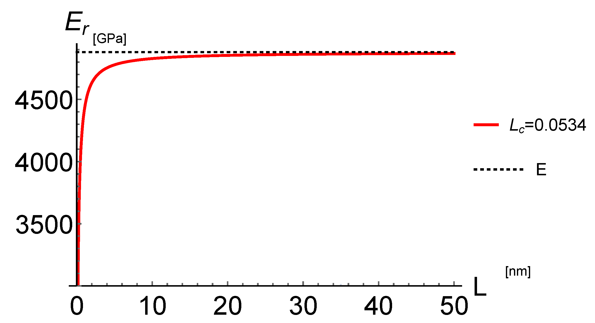
4.2. Reduced Young’s Modulus
In applications, the evaluation of the Young’s modulus of micro- and FG nano-rods is of great interest. Hence, we evaluate the reduced rigidity from Equation (34) to get
Note that the classical rigidity can be recovered if .
Using the reduced rigidity in Equation (36), the axial displacement of the modified nonlocal strain gradient model can be calculated by adopting the classical (local) analysis for rods. Let us consider a constant Young’s elastic modulus so that the elastic area is . Hence, the reduced Young’s modulus can be defined from Equation (36) as
depending on the nonlocal parameter . The upper bound of the nano-rod reduced Young’s modulus for is provided by the local Young’s modulus E. Analogously, for , we recover the local Young’s modulus E and for , the nano-rod reduced Young’s modulus tends to vanish.
To make a comparison, we considered the data presented in [40] for a SWCNT of armchair (10, 10). The diameter d of the SWCNT (n, m) can be calculated by
where the carbon–carbon bond length is nm. The effective thickness of the considered SWCNT is nm and the classical (local) Young’s modulus assumed in [40,44] is GPa.
The Young’s modulus predicted by the MD simulations is reported in [40,44]. Note that the strain gradient elastic theory with high-order boundary conditions was adopted in [40] and the necessity to impose higher-order (non-classical) boundary conditions has the effect that the classical boundary conditions of the classical theory (such as free and clamped boundary conditions) may no longer be meaningful for the modified nonlocal strain gradient rod. As a result, following [28,35], one needs to take into account further boundary conditions involving higher-order stress and strain distributions. Accordingly, four nonlocal nano-rods are considered in [40], depending on the considered higher-order boundary conditions, and for each of them the small-scale parameters are set to match the results of the MD simulations.
On the contrary, the proposed NSG model has no higher-order boundary condition to add so that the classical definitions of external constraints must not be modified. Hence, a unique model of rod can be considered and a unique value of the nonlocal parameter has to be set to match the results of the MD simulations.
In Figure 4 the results provided by Equation (37) are plotted together with the MD data versus the SWCNT length. Upper and lower bounds of the nonlocal parameter nm and nm are reported in Figure 4a to include the values provided by the MD simulations. A good agreement between the Young’s modulus obtained by the NSG model and the MD results could be obtained by setting the nonlocal parameter nm, as shown in Figure 4b.
Figure 4.
SWCNT of armchair (10, 10) having diameter , effective thickness nm and classical (local) Young’s modulus GPa simulated by a CF nano-rod with a concentrated load at the free end. (a) Plot the variation of the Young’s modulus obtained by the NSG method together with the MD data versus the SWCNT length. The upper bound is given for the nonlocal parameter nm and the lower bound is given for the nonlocal parameter nm. (b) Variation of the Young’s modulus obtained by the NSG model and the MD data for the nonlocal parameter nm.
The NSG model provides values of the reduced Young’s modulus tending to the classical (local) value E for increasing values of the SWCNT length L. On the contrary, the values of the MD simulations appear to be constant for values of the SWCNT’s length greater than 27 nm.
The small-scale effect on displacements can be clearly observed in Figure 5 where the non-dimensional maximum displacement , pertaining to the NSG model, is plotted versus the SWCNT’s length L for an applied force nN and the nonlocal parameter ranging in the set nm. As can be seen, the small-scale effect on the displacement can be observed when the length of SWCNT is small and the small-scale effect increases for increasing values of the nonlocal parameter . If , the non-dimensional maximum displacement tends to the corresponding local one
Figure 5.
SWCNT of armchair (10, 10) having diameter nm, effective thickness nm and classical (local) Young’s modulus GPa simulated by a CF nano-rod with a concentrated load nN at the free end. Plot of the non-dimensional maximum displacement of the NSG model vs. the SWCNT’s length L for the nonlocal parameter ranging in the set nm. The non-dimensional local maximum displacement (black dotted line) is
In [45], a continuum mechanics model has been proposed to predict the effective wall thickness of a SWCNT and to calculate its Young’s modulus. The deformation of a central long SWCNT in a bundle of SWCNTs, subjected to an external pressure, has been considered in plane-strain and has been modeled as a thin ring with a mean radius , thickness in the radial direction and a unit width in the axial direction. Hence, it has been obtained that the radius of the nanotube is nm and the predicted thickness is nm so that the related Young’s modulus is GPa. Considering the nonlocal parameter (dependent on the longitudinal atom spacing in armchair CNTs [46,47]) nm as previously calibrated by means of the MD data, the variation law of Young’s modulus obtained by the proposed NSG model for the SWCNT investigated in [45] is reported in Figure 6, with radius nm, thickness nm and Young’s modulus GPa. The NSG model provides values of the reduced Young’s modulus tending to the value GPa for increasing values of the SWCNT length .
Figure 6.
Plot the variation of the Young’s modulus obtained by the NSG method versus the SWCNT length for the nonlocal parameter nm simulated by a CF nano-rod with a concentrated load at the free end. The data of the SWCNT are: diameter nm, effective thickness nm and Young’s modulus GPa.
It is apparent that, for a nanotube with L = 4 nm, the reduced Young’s modulus is GPa, achieving of the value of . Hence, we can conclude that, for the SWCNT considered in [45], the variation of the Young’s modulus is really small if the length of the SWCNT is greater that nm. The small-scale effect on displacements is observed in Figure 7, in which the non-dimensional maximum displacement of the NSG model is plotted versus the SWCNT’s length L for an applied force nN and the nonlocal parameter ranging in the set nm. The small-scale effect on the displacement is apparent and the small-scale effect increases for increasing values of the nonlocal parameter . The non-dimensional maximum displacement tends to the corresponding local displacement if tends to .
Figure 7.
Plot of the non-dimensional maximum displacement of the NSG model vs. the SWCNT’s length for the nonlocal parameter ranging in the set nm. The non-dimensional local maximum displacement (black dotted line) is . The data of the SWCNT are: diameter nm, effective thickness nm and Young’s modulus GPa.
4.3. Case II: CF FG Nano-Rod Subject to a Uniformly Distributed Axial Load
Let us now consider a FG nano-rod with a clamped end at and a free end at subject to a uniformly distributed axial load .
Following the steps reported in Section 3, the axial force N can be evaluated by means of the equilibrium equation so that Equation (24), with the boundary condition , yields . Hence, the closed-form solution of the NSG model for the considered FG nano-rod is obtained by the following nonlocal differential equation
under the CBC in Equation (26)
and the classical boundary condition in Equation (27)
Hence, the axial displacement is
where is the axial displacement of the local model
The maximum axial displacement of the FG nano-rod is attained at the free end and is given by
It is apparent from Equation (42) that the axial displacement u depends on the nonlocal parameters l and . On the contrary, the maximum axial displacement (see Equation (44)) is independent of the nonlocal gradient parameter l.
The limit maximum axial FG nano-rod displacement for the nonlocal parameter is given by the classical (local) displacement of the FG nano-rod.
The non-dimensional axial displacement of the FG nano-rod versus the FG nano-rod non-dimensional length is reported in Figure 8 in terms of the nonlocal non-dimensional parameter for (thick lines) and (dotted lines). The non-dimensional maximum axial displacement increases for increasing values of the nonlocal parameter and is independent of the non-dimensional gradient parameter . The limit FG nano-rod non-dimensional axial displacement for the non-dimensional nonlocal parameter tending to vanish is given by
and is reported with magenta thick line for and dotted line for . Note that .
Figure 8.
CF nano-rod with a uniformly distributed axial load. Plot of the non-dimensional axial displacement , limit non-dimensional axial displacement (black dotted line) and local non-dimensional axial displacement (black dot dashed line) vs. the nano-rod non-dimensional length in terms of the nonlocal non-dimensional parameter in the set and gradient non-dimensional parameter in the set .
The limit non-dimensional axial displacement for is obtained from Equation (42) and is given by
The corresponding plot is reported with the black dotted line in Figure 8 for the considered values of the non-dimensional nonlocal parameter .
4.4. Case III: CC FG Nano-Rod Subject to a Uniformly Distributed Axial Load
Let us consider a fully clamped FG nano-rod subject to a uniformly distributed axial load .
Following the steps reported in Section 3, the axial force is so that the analytical solution of the FG nano-rod is provided as
under the CBC in Equation (26)
and the classical boundary condition in Equation (27)
Hence, the axial displacement is
where is the axial displacement of the local model
Note that we have so that the axial force of the NSG method is and coincides to the local one.
The non-dimensional axial displacement of the FG nano-rod versus the FG nano-rod non-dimensional length is reported in Figure 9 in terms of the nonlocal non-dimensional parameter for (thick lines) and (dotted lines). The non-dimensional midspan axial displacement increases for increasing values of the nonlocal parameter for a given . The limit FG nano-rod non-dimensional axial displacement for the non-dimensional nonlocal parameter tending to vanish follows from Equation (50)
and is reported with magenta thick line for and dotted line for .
Figure 9.
CC nano-rod subject to a uniformly distributed axial load. Plot of the non-dimensional axial displacement , limit non-dimensional axial displacement (black dotted line) and local non-dimensional axial displacement (black dot dashed line) vs. the nano-rod non-dimensional length in terms of the nonlocal non-dimensional parameter in the set and gradient non-dimensional parameter in the set .
The limit non-dimensional axial displacement is obtained from Equation (50) for and is the vanishing one, i.e., . The corresponding plot is reported with the black dotted line in Figure 9.
The 3D plot of the non-dimensional maximum axial displacement for the proposed NSG method versus the non-dimensional characteristic parameters and is reported in Figure 10. It is apparent that the NSG method stiffness or soften the nano-rod depending on the values of the non-dimensional nonlocal and gradient parameters .
Figure 10.
CC nano-rod subject to a uniformly distributed axial load. 3D plot of the non-dimensional maximum axial displacement vs. the non-dimensional characteristic parameters and . The non-dimensional local maximum axial displacement is the horizontal plane.
The cuts of the 3D plot for given values of the non-dimensional parameters and are provided in Figure 11. In particular, the plots of the non-dimensional maximum axial displacement for the NSG method versus the non-dimensional characteristic parameter for and are provided in Figure 11a. It is apparent that for and or and the NSG model is stiffer than the local model and for and or and the NSG model softens the nano-rod. The limit values of the non-dimensional maximum axial displacement for are given by for and by for .
Figure 11.
CC nano-rod subject to a uniformly distributed axial load. (a) The non-dimensional maximum axial displacement for the NSG method vs. the non-dimensional characteristic parameter for and . (b) The non-dimensional maximum axial displacement for the NSG method vs. the non-dimensional characteristic parameters for and .
The plots of the non-dimensional maximum axial displacement for the NSG method versus the non-dimensional characteristic parameter for and are provided in Figure 11b. It is immediate to note that for and or and the NSG model is stiffer than the local model and for and or and the NSG model softens the nano-rod. The limit values of the non-dimensional maximum axial displacement for are given by for and by for .
Finally, a standard numerical analysis of Equation (50) shows that the non-dimensional maximum axial displacement for the proposed NSG method is attained at the midspan and is reported in Table 3 in terms of the non-dimensional nonlocal parameter and gradient parameter . It worth noting that the maximum displacement is attained at the midspan of the FG nano-rod independent of the values of and . The non-dimensional maximum axial displacement of the classical (local) model is . Accordingly, the non-dimensional maximum axial displacements in terms of the pairs , which are less than the non-dimensional maximum classical axial displacements of the FG nano-rod, are reported in italic in Table 3. Hence, the italic values of the non-dimensional maximum axial displacement of the NSG method are smaller than the one of the classical (local) model, thus Table 3 allows one to identify the corresponding pairs having the effect of stiffen or soften the FG nano-rod with respect the classical (local) behavior.
Table 3.
Non-dimensional maximum axial displacement for the proposed NSG method in terms of the non-dimensional parameters and .
5. Conclusions
FG elastic nano-rods under tension have been investigated by the modified nonlocal strain gradient (NSG) theory. The new formulation contains a nonlocal parameter and a material length scale parameter to incorporate the scaling effects of nonlocal stress and microstructure-dependent strain gradient. In comparison to other strain-driven methodologies, the new proposal has been shown to be well-posed and does not require higher-order boundary conditions. In fact, in addition to the classical static and kinematic boundary conditions, closure of the NSG model has to be carried out by prescribing suitable constitutive boundary conditions. Closed-form nonlocal solutions of FG clamped-free and clamped-clamped nano-rods have been provided, exhibiting stiffening or softening effects depending on the values of nonlocal and gradient parameters. Single-Walled Carbon Nanotubes (SWCNT) of armchair (10, 10) were modeled as NSG nano-rods, showing that the new approach could capture the small-scale behavior of Young’s modulus as predicted by the MD simulations. The nonlocal parameter was thus tuned to characterize Young’s modulus vs. the SWCNT length.
Author Contributions
Conceptualization, Methodology, Software, Validation, Investigation, Writing—Review & Editing: R.B., M.Č. and F.M.d.S. All the authors contributed equally to this work.
Funding
This research received no external funding.
Acknowledgments
Financial supports from the Italian Ministry of Education, University and Research (MIUR) in the framework of the Project PRIN 2015 “COAN 5.50.16.01”—code 2015JW9NJT—and from the research program ReLUIS 2018 are gratefully acknowledged.
Conflicts of Interest
The authors declare no conflict of interest.
Appendix A
The reduced stiffness can be alternatively obtained by considering a nano-rod, which is a fully clamped nano-rod with an imposed axial displacement at the end point .
Following the steps reported in Section 3, the axial force is expressed in terms of an unknown parameter in the form so that the solution of the nano-rod is provided by the nonlocal differential equation
under the CBC (Equation (26))
and the classical boundary conditions (Equation (27))
Hence, the axial displacement is
where is the axial displacement of the local model
Moreover, the value of the parameter provides the axial force
and we recover the same value of the reduced stiffness reported in Equation (37).
References
- Eringen, A.C. On differential equations of nonlocal elasticity and solutions of screw dislocation and surface waves. J. Appl. Phys. 1983, 54, 4703–4710. [Google Scholar] [CrossRef]
- Peerlings, R.H.J.; Geers, M.G.D.; de Borst, R.; Brekelmans, W.A.M. A critical comparison of nonlocal and gradient-enhanced softening continua. Int. J. Solids Struct. 2001, 38, 7723–7746. [Google Scholar] [CrossRef]
- Marotti de Sciarra, F.; Barretta, R. A new nonlocal bending model for Euler-Bernoulli nanobeams. Mech. Res. Commun. 2014, 62, 25–30. [Google Scholar] [CrossRef]
- Askes, H.; Aifantis, E.C. Gradient elasticity in statics and dynamics: an overview of formulations, length scale identification procedures, finite element implementations and new results. Int. J. Solids Struct. 2011, 48, 1962–1990. [Google Scholar] [CrossRef]
- Reddy, J.N. Nonlocal theories for bending, buckling and vibration of beams. Int. J. Eng. Sci. 2007, 45, 288–307. [Google Scholar] [CrossRef]
- Barretta, R.; Marotti de Sciarra, F. Analogies between nonlocal and local Bernoulli–Euler nanobeams. Arch. Appl. Mech. 2015, 85, 89–99. [Google Scholar] [CrossRef]
- Romano, G.; Barretta, R. Nonlocal elasticity in nanobeams: the stress-driven integral model. Int. J. Eng. Sci. 2017, 115, 14–27. [Google Scholar] [CrossRef]
- Romano, G.; Barretta, R.; Diaco, M.; Marotti de Sciarra, F. Constitutive boundary conditions and paradoxes in nonlocal elastic nano-beams. Int. J. Mech. Sci. 2017, 121, 151–156. [Google Scholar] [CrossRef]
- Barretta, R.; Diaco, M.; Feo, L.; Luciano, R.; Marotti de Sciarra, F.; Penna, R. Stress-driven integral elastic theory for torsion of nano-beams. Mech. Res. Commun. 2018, 87, 35–41. [Google Scholar] [CrossRef]
- Barretta, R.; Čanadija, M.; Luciano, R.; Marotti de Sciarra, F. Stress-driven modeling of nonlocal thermoelastic behaviour of nanobeams. Int. J. Eng. Sci. 2018, 126, 53–67. [Google Scholar] [CrossRef]
- Barretta, R.; Čanadija, M.; Feo, L.; Luciano, R.; Marotti de Sciarra, F.; Penna, R. Exact solutions of inflected functionally graded nano-beams in integral elasticity. Compos. Part B 2018, 142, 273–286. [Google Scholar] [CrossRef]
- Barati, M.R. On wave propagation in nanoporous materials. Int. J. Eng. Sci. 2017, 116, 1–11. [Google Scholar] [CrossRef]
- Fernández-Sáez, J.; Zaera, R. Vibrations of Bernoulli-Euler beams using the two-phase nonlocal elasticity theory. Int. J. Eng. Sci. 2017, 119, 232–248. [Google Scholar] [CrossRef]
- Vila, J.; Fernández-Sáez, J.; Zaera, R. Nonlinear continuum models for the dynamic behavior of 1D microstructured solids. Int. J. Solids Struct. 2017, 117, 111–122. [Google Scholar] [CrossRef]
- Xu, X.-J.; Zheng, M.-L.; Wang, X.-C. On vibrations of nonlocal rods: Boundary conditions, exact solutions and their asymptotics. Int. J. Eng. Sci. 2017, 119, 217–231. [Google Scholar] [CrossRef]
- Faghidian, S.A. On non-linear flexure of beams based on nonlocal elasticity theory. Int. J. Eng. Sci. 2018, 124, 49–63. [Google Scholar] [CrossRef]
- Faghidian, S.A. Integro-differential nonlocal theory of elasticity. Int. J. Eng. Sci. 2018, 129, 96–110. [Google Scholar] [CrossRef]
- Sahmani, S.; Bahrami, M.; Ansari, R. Nonlinear free vibration analysis of functionally graded third-order shear deformable microbeams based on the modified strain gradient elasticity theory. Compos. Struct. 2014, 110, 219–230. [Google Scholar] [CrossRef]
- Polizzotto, C.; Fuschi, P.; Pisano, A.A. A nonhomogeneous nonlocal elasticity model. Eur. J. Mech. A/Solids 2006, 25, 308–333. [Google Scholar] [CrossRef]
- Fuschi, P.; Pisano, A.A.; Polizzotto, C. Size effects of small-scale beams in bending addressed with a straindifference based nonlocal elasticity theory. Int. J. Mech. Sci. 2019, 151, 661–671. [Google Scholar] [CrossRef]
- Mindlin, R.D. Micro-structure in linear elasticity. Arch. Ration. Mech. Anal. 1964, 16, 51–78. [Google Scholar] [CrossRef]
- Akgöz, B.; Civalek, Ö. Longitudinal vibration analysis of strain gradient bars made of functionally graded materials (FGM). Compos. Part B 2013, 55, 263–268. [Google Scholar] [CrossRef]
- Rahaeifard, M. Size-dependent torsion of functionally graded bars. Compos. Part B 2015, 82, 205–211. [Google Scholar] [CrossRef]
- Akgöz, B.; Civalek, Ö. Strain gradient elasticity and modified couple stress models for buckling analysis of axially loaded micro-scaled beams. Int. J. Eng. Sci. 2011, 49, 1268–1280. [Google Scholar] [CrossRef]
- Ghayesh, M.H.; Farokhi, H.; Alici, G. Size-dependent performance of microgyroscopes. Int. J. Eng. Sci. 2016, 100, 99–111. [Google Scholar] [CrossRef]
- Guo, J.; Chen, J.; Pan, E. Static deformation of anisotropic layered magnetoelectroelastic plates based on modified couple-stress theory. Compos. Part B 2016, 107, 84–96. [Google Scholar] [CrossRef]
- Lim, C.W.; Zhang, G.; Reddy, J.N. A higher-order nonlocal elasticity and strain gradient theory and its applications in wave propagation. J. Mech. Phys. Solids 2015, 78, 298–313. [Google Scholar] [CrossRef]
- Fernandes, R.; El-Borgi, S.; Mousavi, S.; Reddy, J.; Mechmoum, A. Nonlinear size-dependent longitudinal vibration of carbon nanotubes embedded in an elastic medium. Physica E 2017, 88, 18–25. [Google Scholar] [CrossRef]
- Guo, S.; He, Y.; Liu, D.; Lei, J.; Shen, L.; Li, Z. Torsional vibration of carbon nanotube with axial velocity and velocity gradient effect. Int. J. Mech. Sci. 2016, 119, 88–96. [Google Scholar] [CrossRef]
- Li, L.; Hu, Y.; Li, X. Longitudinal vibration of size-dependent rods via nonlocal strain gradient theory. Int. J. Mech. Sci. 2016, 115, 135–144. [Google Scholar] [CrossRef]
- Li, L.; Hu, Y.; Ling, L. Flexural wave propagation in small-scaled functionally graded beams via a nonlocal strain gradient theory. Compos. Struct. 2015, 133, 1079–1092. [Google Scholar] [CrossRef]
- Simsek, M. Nonlinear free vibration of a functionally graded nanobeam using nonlocal strain gradient theory and a novel hamiltonian approach. Int. J. Eng. Sci. 2016, 105, 12–27. [Google Scholar] [CrossRef]
- Shen, Y.; Chen, Y.; Li, L. Torsion of a functionally graded material. Int. J. Eng. Sci. 2016, 109, 14–28. [Google Scholar] [CrossRef]
- Barati, M.R.; Zenkour, A. A general bi-helmholtz nonlocal strain-gradient elasticity for wave propagation in nanoporous graded double-nanobeam systems on elastic substrate. Compos. Struct. 2017, 168, 885–892. [Google Scholar] [CrossRef]
- Li, L.; Hu, Y. Nonlinear bending and free vibration analyses of nonlocal strain gradient beams made of functionally graded material. Int. J. Eng. Sci. 2016, 107, 77–97. [Google Scholar] [CrossRef]
- Ebrahimi, F.; Dabbagh, A. Wave dispersion characteristics of orthotropic double-nanoplatesystem subjected to a longitudinal magnetic field. Microsyst. Technol. 2018, 24, 2929–2939. [Google Scholar] [CrossRef]
- Mirkalantari, S.A.; Hashemian, M.; Eftekhari, S.A.; Toghraie, D. Pull-in instability analysis of rectangular nanoplate based on strain gradient theory considering surface stress effects. Physica B 2017, 519, 1–14. [Google Scholar] [CrossRef]
- Li, L.; Li, X.; Hu, Y. Free vibration analysis of nonlocal strain gradient beams made of functionally graded material. Int. J. Eng. Sci. 2016, 102, 77–92. [Google Scholar] [CrossRef]
- Xu, X.J.; Wang, X.C.; Zheng, M.L.; Ma, Z. Bending and buckling of nonlocal strain gradient elastic beams. Compos. Struct. 2017, 160, 366–377. [Google Scholar] [CrossRef]
- Zhu, X.; Li, L. Closed form solution for a nonlocal strain gradient rod in tension. Int. J. Eng. Sci. 2017, 119, 16–28. [Google Scholar] [CrossRef]
- Xu, X.-J.; Zhou, B.; Zheng, M.-L. Comment on “Free vibration analysis of nonlocal strain gradient beams made of functionally graded material” [Int. J. Eng. Sci. 2016, 102, 77–92]. Int. J. Eng. Sci. 2017, 119, 189–191. [Google Scholar] [CrossRef]
- Barretta, R.; Marotti de Sciarra, F. Constitutive boundary conditions for nonlocal strain gradient elastic nano-beams. Int. J. Eng. Sci. 2018, 130, 187–198. [Google Scholar] [CrossRef]
- Apuzzo, A.; Barretta, R.; Faghidian, S.A.; Luciano, R.; Marotti de Sciarra, F. Free vibrations of elastic beams by modified nonlocal strain gradient theory. Int. J. Eng. Sci. 2018, 133, 99–108. [Google Scholar] [CrossRef]
- Duan, K.; Li, L.; Hu, Y.; Wang, X. Enhanced interfacial strength of carbon nanotube/copper nanocomposites via Ni-coating: Molecular-dynamics insights. Physica E 2017, 88, 259–264. [Google Scholar] [CrossRef]
- Vodenitcharova, T.; Zhang, L.C. Effective wall thickness of a single-walled carbon nanotube. Phys. Rev. B 2003, 68, 165401. [Google Scholar] [CrossRef]
- De Domenico, D.; Askes, H. Stress gradient, strain gradient and inertia gradient beam theories for the simulation of flexural wave dispersion in carbon nanotubes. Compos. Part B 2018, 153, 285–294. [Google Scholar] [CrossRef]
- De Domenico, D.; Askes, H. Nano-scale wave dispersion beyond the First Brillouin Zone simulated with inertia gradient continua. J. Appl. Phys. 2018, 124, 205107. [Google Scholar] [CrossRef]
© 2019 by the authors. Licensee MDPI, Basel, Switzerland. This article is an open access article distributed under the terms and conditions of the Creative Commons Attribution (CC BY) license (http://creativecommons.org/licenses/by/4.0/).