Featured Application
Navigation for a service robot with facial and gender recognition capabilities in an indoor environment with static and dynamic obstacles.
Abstract
This paper investigates the use of an autonomous service robot in an indoor complex environment, such as a hospital ward or a retirement home. This type of service robot not only needs to plan and find paths around obstacles, but must also interact with caregivers or patients. This study presents a type of service robot that combines the image from a 3D depth camera with infrared sensors, and the inputs from multiple sonar sensors in an Adaptive Neuro-Fuzzy Inference System (ANFIS)-based approach in path planning. In personal contacts, facial features are used to perform person recognition in order to discriminate between staff, patients, or a stranger. In the case of staff, the service robot can perform a follow-me function if requested. The robot can also use an additional feature which is to classify the person’s gender. The purpose of facial and gender recognition includes helping to present choices for suitable destinations to the user. Experiments were done in cramped but open spaces, as well as confined passages scenarios, and in almost all cases, the autonomous robots were able to reach their destinations.
1. Introduction
Today’s workers in care-taking facilities have their hands full taking care of patients, thus require help for everyday routines. There are many branches of investigation into using machines to help out with daily routines in the health-care industry, such as gesture recognition [], or pedestrian movement prediction []. We choose to investigation helpful tasks, such as delivering proper medicines to target patients, or helping to carry heavy loads in follow-me mode, performed by an autonomous robot with face and gender recognition abilities. For these purposes, this paper presents a tri-wheeled autonomous service robot equipped with a camera, an RGB-Depth (RGB is acronym for Red, Green, and Blue) sensor, and sonar sensors. It has built-in facial recognition ability, ability to separate staff or patients from visitors, and it can also distinguish the gender of a visitor for record-keeping purposes. By recognizing staff, it can offer the staff functions not available to patients or visitors, such as the follow-me function. By recognizing patients, it can help dispense the proper medication to each individual patient. A possible scenario for this robot could be using it to dispense medicine to selected patients who may be walking around the hallways. In navigation, it can avoid static as well as dynamic obstacles while moving toward its objective, using a dual-level Adaptive Neuro-Fuzzy Inference System (ANFIS)-based fuzzy controller. It uses a depth-map to detect obstacles ahead, then uses image processing techniques to extract information as input into an ANFIS-based fuzzy system for analysis in order for the service to be able to avoid obstacles. The robot also incorporates sonar information using another ANFIS-based fuzzy system when it determines that depth-map information is insufficient.
In 1998, Yamauchi and Schultz [] proposed an idea to include extra distance sensors on robots, such as laser distance sensors and ultrasound distance sensors. The distance sensors can aid in detecting surrounding objects or obstacles in real time so that the robot can locate or correct itself using known map data. However, the high costs of the precision sensors make them unsuitable for popular use. Even though ultrasonic sensors are relatively cheap by comparison, their deviation of errors is wider and they have detection blind spots; the detection distance is only proportional to the volume of the sound generator. Prahlad [] proposed a driver-less car that has face detection and tracking capabilities. Similarly, we added onto our architecture the ability to perform face and gender recognition. Correa [] proposed the development of a sensing system in an indoor environment, allowing the robot to have autonomous navigation and the ability for identification of its environment. His proposed system consisted of two parts: The first part is a reactive navigation system where the robot uses the RGB-Depth sensor to receive depth information and uses the arrangement of obstacles as the basis to determine the path to avoid the obstacles indoors; the second part uses an artificial neural network to identify different configurations of the environment. Csaba [] introduced an improved version based on fuzzy rules. His system uses 16 rules, three inputs and one output, one Mamdani-type fuzzy controller, and obtained acceptable results in real-time experiments. In 2016, Algredo-Badillo [] presented the possibility of a fuzzy control system, with the output from depth sensor as its input, for an autonomous wheelchair as a possible design. In 2018, de Silva [] and Jin et al. [] show that fusion of data from multiple sensors can perform better than a single sensor for a driver-less vehicle.
Our study builds an autonomous robot with a camera, a RGB-depth sensor, and sonar sensors. Prior to moving, the robot scans the entire room with a pre-trained pedestrian classifier in order to determine if a targetable person or persons exist that need to be tracked. If the robot locates its target and moves toward the person, the person’s face is located and facial and gender recognitions would be performed simultaneously in order to determine if the target person’s identity is in the database or if the person is a stranger. While moving, the dual sensor inputs to the fuzzy-based real-time obstacle avoidance system are used for path planning. The target person can then input target location and follows the robot or activates the robot’s follow-me function instead. Using the follow-me function, the robot can help carry heavy loads for the user. The flowchart of the system is shown below in Figure 1.
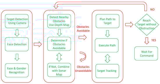
Figure 1.
The system flowchart.
2. Method
2.1. Facial Recognition
We used OpenCV’s LPBH (Local Binary Patterns Histogram) face recognizer method [], which uses Local Binary Patterns Histogram as descriptors. It has shown to work better than the EigenFaces [] or the FisherFaces [] face recognizer methods under different environments and lighting conditions, and can reach an accuracy rate of more than 94% when 10 or more faces per person are used during its training []. The training and testing datasets were taken from Aberdeen [], GUFD [], and Utrecht ECVP []. Pictures of laboratory personnel were later insert into the training dataset. The purpose of adding face and gender recognition is so that the robot can locate an assigned target or targets, then performs its assigned tasks accordingly. The flowchart for face and gender recognition is shown in Figure 2.
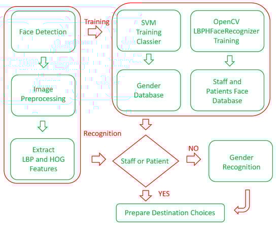
Figure 2.
Facial and gender recognition flowchart.
2.2. Gender Recognition
In the gender identification part, the features with higher classification accuracy are selected from LBP [] and HOG (Histogram of Oriented Gradients) [] of different scales, and then screened using p-values before being combined. The advantage of this method is that it uses the differences between LBP and HOG methods of calculation to increase the classification accuracy. Simple experiments show that the results of combining both is higher than using either one alone. In addition, using the p-value to filter can be used to pick out features that are more prominent, so that the number of classification features required would be greatly reduced, and the time required for training or testing could also be improved.
After p-value is used to filter the statistical values of the texture features of HOG and LBP, the more robust features in the training samples are used to train a SVM (Support Vector Machine) [] model, which is used as the basis for the classification of the test samples. The training and testing data were taken from the same online databases for facial recognition. We compared the accuracy rates of LBP, HOG, and LPB + HOG + p-value filtering. The results are shown below in Table 1. The rate of success of HOG + LBP + p-value filtering has reached 92.6%.

Table 1.
Comparison of Gender Classification Accuracy Using Different Features.
2.3. Object Segmentation
Object segmentation is performed using map from the depth sensor. An example of depth map vs. standard RGB camera is shown below in Figure 3.
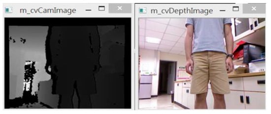
Figure 3.
Example of depth map vs. standard camera image.
A depth map includes all objects nears and far, and contains too much information for accurate processing, so we decided that the threshold of the depth map should first be limited by a depth value less or equal to 1.5 m. An example result is shown below in Figure 4:
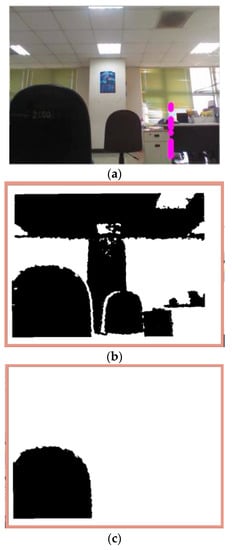
Figure 4.
(a) Camera image, (b) depth map, (c) depth map threshold of 1.5 m.
At this range, generally the obstacles tend to be at the bottom of the depth image. In order to speed up the process, we extract the regions of interest (ROI) from the entire image by disregarding the depth information from above the middle of the height of the image. This is also to avoid the effects of lighting from above. In Correa’s paper [], he listed eight possible scenarios for obstacle arrangement; where the scene is divided into five parts, and if any of the space is occupied by an obstacle then it is marked, as shown in Figure 5. For example, the obstacle arrangement in Figure 4c is the scenario of Figure 5d.
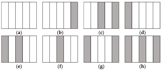
Figure 5.
Correa’s eight obstacles scenarios. (a) No obstacle; (b) One obstacle at the far right; (c) Two obstacles at the right, separated by a gap; (d) One obstacle at the far left; (e) Two obstacles at the left, separated by a gap; (f) An obstacle at the middle; (g) Two obstacles at the far right and far left; (h) Three obstacles separated by two gaps.
In the most likely cases are cases (f–h), scenarios where the robot uses Correa’s method randomly move left or right, and can easily make the wrong decision. So instead of detecting obstacle arrangement first before moving, we decided that the robot should actively seek gaps between obstacles while moving in order to find the largest gap and judge if there is a chance to pass through. Figure 6 shows the various gaps detected using this method. The proposed method would be more proactive than that proposed by Correa.
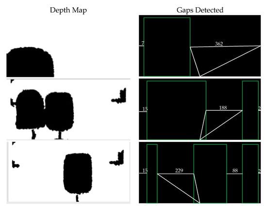
Figure 6.
Threshold depth maps and detected gaps.
2.4. Robot Movements in the Presence of Obstacles
There are five possible commands for the robots to move: forward, toward left, toward right, pause, and turn around. Forward command is issued when fuzzy analysis of the obstacles shows that there is a gap in the middle that is passable. There is a necessary initial condition for the robot to move forward: that within its depth sensor’s field-of-view, at least one passable gap exists. If this initial condition does not exist, then the robot can turn around, move forward a little, then turn around again in order to increase its field-of-view. The turn towards left command is issued if the fuzzy analysis of the obstacles determines that there is a gap wide enough to pass and the center of the gap is toward the left of the depth map, but it is not a hard right, rather at an angle that causes the robot to move toward the center of the gap; similarly for the turn towards right command. The turnaround command is issued when fuzzy analysis determines that there is no gap wide enough to pass through. The pause command is issued if additional information from the sonar is required. The flowchart for obstacle avoidance is shown below in Figure 7.
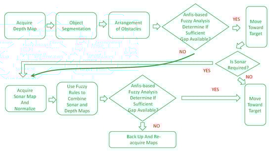
Figure 7.
The flowchart for robot’s obstacle avoidance.
2.5. ANFIS-Based Fuzzy System
ANFIS is the acronym for Adaptive Neuro-Fuzzy Inference System. An ANFIS [] system structure for two variables and two rules is shown in Figure 8, where
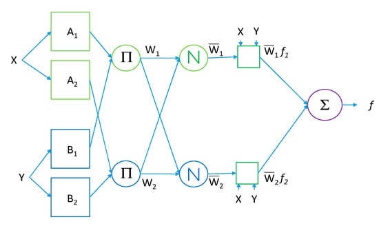
Figure 8.
The ANFIS-based fuzzy system for two rules.
- Rule 1: If input x is A1 and input y is B1,
- Then f1 = p1x + q1y + r1.
- Rule 2: If input x is A2 and input Y is B2,
- Then f2 = p2x + q2y + r2.
Then the output f is a linear combine of weighted f1 and f2. In Figure 8, the first layer is input layer, which contains the membership functions of variables. The second layer is the rule layer, which gets fuzzy rules from the combinations of the membership function of each variable. The third layer is the normalization layer, which normalizes the results from the previous layer. The fourth layer is the inference layer. The fifth layer is output layer, which calculates the sum from previous layer’s output values. De-fuzzification is then performed on the output.
In our system, there are two fuzzy systems, as shown in Figure 7, where the first system uses depth map alone in determining whether a crossable gap exists between obstacles. In the second system, where depth map alone is determined to be insufficient for accurate judgement of the closeness of obstacles, the input from sonars are then used in addition to the depth map as inputs. In the following subsections, we will discuss these two fuzzy systems.
2.5.1. Fuzzy System Using Depth Map Alone
Because our RGB-Depth sensor is only accurate for obstacles up to 1.5 m away, there is a possibility of mis-judging gap width, and that a crossable gap may be judged as not crossable. Therefore, this is where the first fuzzy system is used to judge whether a gap is crossable. We use as input the value of the depth map, and the absolute difference between the depth values of neighboring obstacles. COG (Center of Gravity) is used as the de-fuzzification method. The 9 rules are shown in Table 2. The threshold values of 400 and 700 were determined experimentally first.
Table 2.
Fuzzy rules for using depth map alone.
An example using these rules is shown in Figure 9, where the gap value is 241, around the robot’s width, and the depth difference between neighbors is 663; the 9 rows in Figure 9 represent inputs and outputs for each of the 9 fuzzy rules. The bottom right graph is the visualization for the final output. The red lines for the input columns are visual representation of the input values.
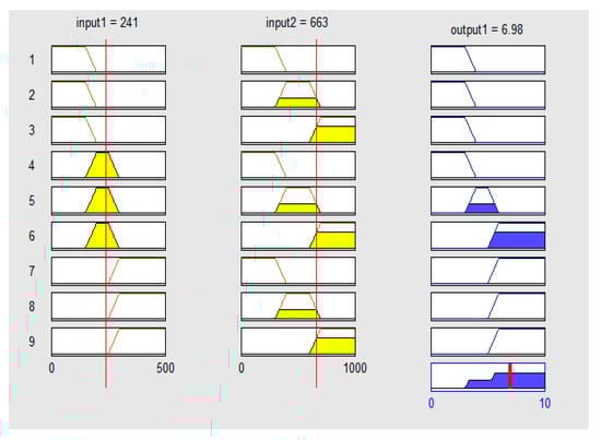
Figure 9.
An example of fuzzy-rules-based decision.
2.5.2. Combining Sensors
One drawback using the depth map is the problem that if the obstacles are too low and too close to the robot, then they are undetectable by using the depth map alone. In this case, the sonars will be activated as aid in obstacle-avoidance. However, judging how much weight should be given to the depth map or the sonar map in order to yield the optimal map so as to find the largest available gap is a problem. It requires solving the weights in Equation (1) at each instance of decision making:
(Result Map) = Wd * (Depth Map) + Ws * (Normalized Sonar Map)
The field of research of combining sonar map with other sensors, such as depth map, is still an area that requires exploration [,]. The sonar map can only be used for obstacles that are close, so using the sonar map alone may cause the robot to spin continuously in order to acquire more information. Because of this, our research uses the depth map to move the robot until it moves too close to the gap or obstacles and determines that additional information would be required, then it activates the sonar system in order to acquire the sonar map. There are eight sonar sensors installed in a semi-circular fashion, as illustrated in Figure 10.
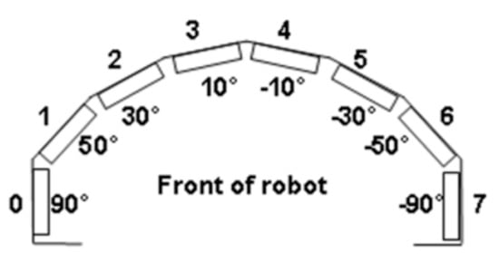
Figure 10.
Placement of sonar sensors near our robot’s base.
However, the leftmost and rightmost sensors are not used because they seem to cause erroneous decisions. The sonar signals are first normalized between 0 and 1.0, and it is determined that signal strength less than 0.4 indicates that obstacles are close, while greater than 0.6 indicates that obstacles are far away. If each of the six sonar signals are used as individual fuzzy inputs, then the system would become overly complicated. Therefore, in order to reduce the number of fuzzy rules, the signals for the left three sensors are averaged into a single input, and the signals for the right three sensors are averaged into another single input. This would effectively reduce the number of fuzzy rules. We designed a total of 8 fuzzy rules for combining the sensors. They are listed in Table 3.
Table 3.
Fuzzy rules for combining sensors.
An example of using these rules as shown in Figure 11, where gap width is around the robot’s width, the normalized and averaged value for left sonar is 0.259, and the normalized and averaged value for right sonar is 0.729. The eight rows in Figure 11 represents the inputs and outputs for the 8 rules. The red lines are symbolic representations of the input values.
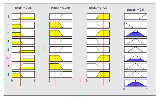
Figure 11.
An example of using fuzzy rules to combine sensors input.
Figure 12 shows the paths the robot takes when decisions are made based on using fuzzy rules to combine sonar map and depth map versus using only the sonar map alone. In situations like this, we can see the advantage of combining the inputs of sensors.
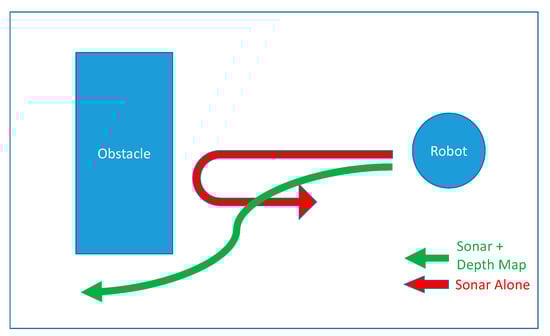
Figure 12.
The path our robot takes when using sonars alone vs. combining sensors.
3. Experiment
3.1. Setup
The experimental robot is shown in Figure 13, with camera and RGB-Depth sensor on its top and middle, respectively. The sonar sensors are located below. Its width is 381 mm, and it has a swing radius of 26.7 cm. Its software is running on a laptop located in the middle.
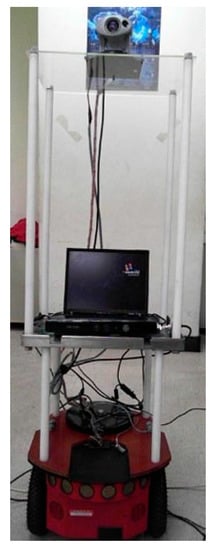
Figure 13.
The experimental robot.
The experiments are divided into 2 subsections. The first is the face recognition plus gender determination. The second subsection is to test the obstacle avoidance capability of the robot. This particular subsection is further divided into situations when the obstacles are static, and when the obstacles are moving (e.g., pedestrians). These experiments were performed in real-time. These experiments were performed in an area of about 7 m by 3 m, with office chairs as obstacles.
3.2. Face and Gender Recognition
In the first experiment, the robot is placed a little distance away from the human person. The robot would adjust its orientation and distance to the human person so as to place the human face, detected using Viola’s method [], square in the middle of its field-of-view, and tracked using the KLT feature tracker []. The training sample included 400 male photos and 300 female photos. The test samples included 265 male photos and 227 female photos. The correct gender recognition rate was 92.6829%. Later, 10 photos of each laboratory personnel were added to the training set, and the robot was able to perform on-line face recognition during the test, and recognize the human persons in front as laboratory personnel and correctly classified their gender. After recognition and classification, choices for destinations are then presented to the user via the monitor based on the result, including a Follow-Me choice for lab workers. Examples of classification results are shown in Figure 14.
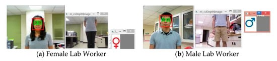
Figure 14.
Examples of facial recognition and gender classification.
3.3. Obstacles Avoidance
3.3.1. Static Obstacle Avoidance
In the static obstacles experiment, the testing site is a hallway. The obstacles are placed along the hallway, as shown in Figure 15.
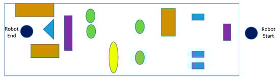
Figure 15.
Static obstacles for the robot.
Sufficient gaps are left between the obstacles so that the robot should be able to reach its final destination. The following plot, Figure 16, shows the path the robot took. The robot’s position was recorded at an interval of every 10 s.
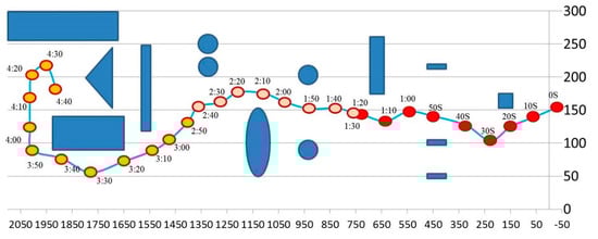
Figure 16.
The path the robot took with positions taken at 10 s interval.
There are a total of 17 possible scenarios designed along the path that we think that the robot would need to make critical decisions about whether to incorporate sonar sensors in its decisions. The following figure, Figure 17, shows where each of the 17 scenarios, T1–T17, took place, and Table 4 shows the input values and the robot’s decisions for the 17 scenarios.
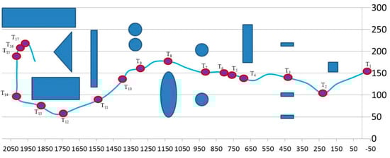
Figure 17.
The seventeen scenarios (T1–T17) where decisions of the robot were recorded.
Table 4.
Sensors Inputs and Decision for Scenarios T1–T17.
Figure 18 shows the fuzzy inputs and outputs at T1–T17.
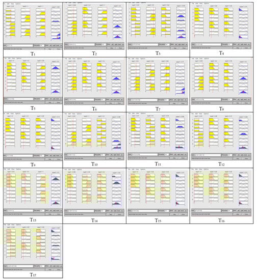
Figure 18.
Fuzzy inputs and decisions for combining sensor maps at T1–T17.
Table 5 below illustrates the comparisons between our method, Correa’s method [], and Csaba’s method [], using single-point analysis at each scenario point. Success is defined as being able to avoid collision.
Table 5.
Comparisons between Correa, Csaba, and our proposed method on T1–T17 scenarios.
3.3.2. Dynamic Obstacle Avoidance
Eleven scenarios were setup using one or two moving obstacles for this experiment. The obstacles are to simulate pedestrians in a service environment, and none was the robot’s target. Table 6 illustrates these scenarios.
Table 6.
Eleven scenarios for dynamic moving obstacles.
Figure 19 illustrates how the robot responded at each of these scenarios. The red line represents the path of the robot, the blue line represents the path of the first obstacle, and orange line represents the path of the second obstacle. Each dot represents sampled locations taken between fixed time intervals. In each of these scenarios, except for the third, the robot was able to pass through the obstacles and reach the other side. In the third scenario, the robot was able to avoid collision by turning around.
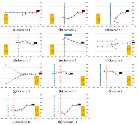
Figure 19.
The paths of the moving obstacles (blue, orange) and the robot (red) for the 11 scenarios.
4. Discussion and Conclusions
In this paper, we presented a service robot with face recognition and gender classification abilities, with accuracy reaching 92.68%. The service robot can perform different tasks based on the classification results, such as activating the Follow-Me function for laboratory staff only. Possible uses of the robots including delivering medicines to target patients, assist visitors to find patients, and other tasks. We also developed a dual-level ANFIS-based fuzzy obstacle-avoidance system based on the inputs from two different types of sensors: RGB-Depth and sonars. It is found that the obstacle-avoidance capability using both types of sensors surpasses the performance of using just a single type sensor. We performed the experiment testing the obstacle avoidance capability of the robot under both static and dynamic environments and found that the robot can successfully maneuver around obstacles in almost all cases. In the future, we hope to improve the robot’s navigation abilities by including advanced path planning using indoor maps of the environment, or different hardware configurations for other purposes.
Author Contributions
Conceptualization, methodology, analysis, writing, J.-C.C. and J.-D.L.; Experiments, Z.-Y.D.
Funding
The work was partly supported by Ministry of Science and Technology (MOST) and Chang Gung Memorial Hospital, Taiwan, Republic of China, under Grant MOST107-2221-E-182-026-MY2 and CMRPD2G0121.
Conflicts of Interest
The authors declare no conflict of interest.
References
- Yang, G.; Lv, H.; Chen, F.; Pang, Z.; Wang, J.; Yang, H.; Zhang, J. A Novel Gesture Recognition System for Intelligent Interaction with a Nursing-Care Assistant Robot. Appl. Sci. 2018, 8, 2349. [Google Scholar] [CrossRef]
- Chen, Z.; Song, C.; Yang, Y.; Zhao, B.; Hu, Y.; Liu, S.; Zhang, J. Robot Navigation Based on Human Trajectory Prediction and Multiple Travel Modes. Appl. Sci. 2018, 8, 2205. [Google Scholar] [CrossRef]
- Yamauchi, B.; Shultz, A.; Adams, W. Mobile robot exploration and map-building with continuous localization. In Proceedings of the Internet Content Rating Association (ICRA), Leuven, Belgium, 20 May 1998; Volume 4, pp. 3175–3720. [Google Scholar]
- Vadakkepat, P.; Lim, P.; de Silva, L.C.; Jing, L.; Ling, L.L. Multimodal Approach to Human-Face Detection and Tracking. IEEE Trans. Ind. Electron. 2008, 55, 1385–1393. [Google Scholar] [CrossRef]
- Correa, D.S.O.; Sciotti, D.F.; Prado, M.G.; Sales, D.O.; Wolf, D.F.; Osorio, F.S. Mobile Robots Navigation in Indoor Environments Using Kinect Sensor. In Proceedings of the 2012 Second Brazilian Conference on Critical Embedded Systems, São Paulo, Brazil, 21–25 May 2012; pp. 36–41. [Google Scholar]
- Csaba, G. Fuzzy Based Obstacle Avoidance for Mobil Robots with Kinect Sensor. In Proceedings of the 2012 4th IEEE International Symposium on Logistics and Industrial Informatics (LINDI), Smolenice, Slovakia, 5–7 September 2012; pp. 135–144. [Google Scholar]
- Algredo-Badillo, I.; Morales-Raales, L.A.; Hernández-Gracidas, C.A.; Cortés-Pérez, E.; Pimentel, J.J.A. Self-navigating Robot based on Fuzzy Rules Designed for Autonomous Wheelchair Mobility. Int. J. Comput. Sci. Inf. Secur. 2016, 14, 11–19. [Google Scholar]
- de Silva, V.; Roche, J.; Kondoz, A. Fusion of LiDAR and Camera Sensor Data for Environment Sensing in Driverless Vehicles. 2018. Available online: https://dspace.lboro.ac.uk/2134/33170 (accessed on 10 November 2018).
- Jin, X.-B.; Su, T.-L.; Kong, J.-L.; Bai, Y.-T.; Miao, B.-B.; Dou, C. State-of-the-Art Mobile Intelligence: Enabling Robots to Move Like Humans by Estimating Mobility with Artificial Intelligence. Appl. Sci. 2018, 8, 379. [Google Scholar] [CrossRef]
- OpenCV. Available online: http://www.opencv.org/ (accessed on 2 September 2018).
- Turk, M.; Pentland, A. Eigenfaces for recognition. J. Cogn. Neurosci. 1991, 3, 71–86. [Google Scholar] [CrossRef] [PubMed]
- Belhumeur, P.N.; Hespanha, J.P.; Kriengman, D.J. Eigenfaces vs. fisherfaces: Recognition using class specific linear projection. IEEE Trans. Pattern Anal. Mach. Intell. 1997, 19, 711–720. [Google Scholar] [CrossRef]
- Chien, L.W.; Ho, Y.F.; Tsai, M.F. Instant Social Networking with Startup Time Minimization Based on Mobile Cloud Computing. Sustainability 2018, 10, 1195. [Google Scholar] [CrossRef]
- Aberdeen Facial Database. Available online: http://pics.psych.stir.ac.uk/zips/Aberdeen.zip (accessed on 10 February 2017).
- GUFD Facial Database. Available online: http://homepages.abdn.ac.uk/m.burton/pages/gfmt/Glasgow%20Face%20Recognition%20Group.html (accessed on 10 February 2017).
- Utrecht ECVP Facial Database. Available online: http://pics.psych.stir.ac.uk/zips/utrecht.zip (accessed on 10 February 2017).
- Ullah, I.; Aboalsamh, H.; Hussain, M.; Muhammad, G.; Mirza, A.; Bebis, G. Gender Recognition from Face Images with Local LBP Descriptor. Arch. Sci. J. 2012, 65, 353–360. [Google Scholar]
- Ren, H.; Li, Z. Gender Recognition Using Complexity-Aware Local Features. In Proceedings of the 2014 22nd International Conference on Pattern Recognition, Stockholm, Sweden, 24–28 August 2014; pp. 2389–2394. [Google Scholar]
- Moghaddam, B.; Yang, M.-H. Gender Classification with Support Vector Machines. In Proceedings of the Fourth IEEE International Conference on Automatic Face and Gesture Recognition, Grenoble, France, 28–30 March 2000; p. 306. [Google Scholar]
- Jang, J.-S.R. ANFIS: Adaptive-network-based fuzzy inference system. IEEE Trans. Syst. Man Cybern. 1993, 23, 665–685. [Google Scholar] [CrossRef]
- Flynn, A.M. Combining Sonar and Infrared Sensors for Mobile Robot Navigation. Int. J. Robot. Res. 1988, 7, 5–14. [Google Scholar] [CrossRef]
- Elfes, A.; Matthies, L. Sensor integration for robot navigation: Combining sonar and stereo range data in a grid-based representataion. In Proceedings of the 26th IEEE Conference on Decision and Control, Los Angeles, CA, USA, 9–11 December 1987; pp. 1802–1807. [Google Scholar]
- Viola, P.; Jones, M.J. Rapid Object Detection using a Boosted Cascade of Simple Features. In Proceedings of the IEEE Computer Society International Conference on Computer Vision and Pattern Recognition, Kauai, HI, USA, 8–14 December 2001; Volume 1, pp. 511–518. [Google Scholar]
- Tomasi, C.; Kanade, T. Detection and Tracking of Point Features; Technical Report CMU-CS_91-132; Carnegie Mellon University: Pittsburgh, PA, USA, 1991. [Google Scholar]
© 2019 by the authors. Licensee MDPI, Basel, Switzerland. This article is an open access article distributed under the terms and conditions of the Creative Commons Attribution (CC BY) license (http://creativecommons.org/licenses/by/4.0/).