Article

Steel Fiber Use as Shear Reinforcement on I-Shaped UHP-FRC Beams

Department of Civil Engineering, Balikesir University, Balikesir 10145, Turkey
*
Author to whom correspondence should be addressed.
Appl. Sci. 2019, 9(24), 5526; https://doi.org/10.3390/app9245526
Submission received: 4 November 2019 / Revised: 9 December 2019 / Accepted: 11 December 2019 / Published: 16 December 2019
(This article belongs to the Special Issue Fiber-Reinforced Concrete)

Abstract

:
In the presented paper, the effectiveness of steel fiber use on the shear and flexure behaviors of ultra-high performance concrete (UHPC) beams and the feasibility of steel fibers in place of shear reinforcement were investigated experimentally. In this framework, a total of four I-shaped UHPC beams were produced for a high tensile reinforcement ratio of 2.2%. While two of them were non-fiber UHPC beams with and without the shear reinforcement to show the contribution of steel fibers, the remaining beams were made from the ultra-high performance steel fiber-reinforced concrete (UHP-FRC) having the short straight fibers with 1.5% and 2.5% by volume. The shear and flexural parameters, such as the load–deflection response, cracking pattern, failure mode, deflection, and curvature ductilities were discussed based on the four-point loading test results. While the reference beam without fiber and shear reinforcement failed by the shear with a sudden load drop before the yielding of reinforcement and produced no deflection capability, the inclusion of steel fibers to the UHPC matrix transformed the failure mode from shear to flexure through the fibers’ crack-bridging ability. It might be deduced that the moderate level of steel fiber use in the UHP-FRC beams may take the place of shear reinforcement in practical applications.

1. Introduction

Based on various studies conducted on the concrete technology in recent years, the use of ultra-high performance concrete (UHPC) has become one of the most popular products. This type of special concrete is used in many areas to eliminate the disadvantages in traditional reinforced concrete member design due to its very high compressive strength and post-cracking tensile response. Even though several studies were carried out, there is no authority or standard to classify the term of ultra-high performance. However, some conditions for this classification, such as the concrete compressive strength and pseudo strain-hardening under tension, are expected to ensure in some way [1,2,3,4]. Note that the pseudo strain-hardening response can be ensured with a good amount of fiber content. However, insufficient fiber volume fraction and/or low concrete compressive strength may lead to softening response [5]. In this sense, when the minimum compressive strength of 150 MPa and the strain-hardening response are ensured with sufficient steel fiber amounts, this type of composite material is widely categorized as the steel fiber-UHPC (SF-UHPC) or ultra-high performance fiber reinforced concrete (UHP-FRC) [1,2,6,7,8,9,10].
The mechanical properties of UHP-FRC were improved by using a fine granular material, a very low water-to-binder ratio, and some admixture materials such as superplasticizer, air-entraining agent, so on [11,12]. In addition, the randomly dispersed steel fibers to the concrete mixture, which may be in straight, end-hooked, twisted, or other forms, improve the capacity in many different ways, such as the ductility, energy absorption capacity, and strength. When compared to the normal-strength fibrous concrete, the UHP-FRC has pretty good compressive and tensile strengths, strain capacity, and durability through its high-density matrix [1,8,9,13,14,15,16]. The UHP-FRC’s superior characteristics allow the use of higher reinforcement ratios over the limits stipulated in the design codes. Consequently, these advantages in terms of the ductility, stiffness, and strength make it possible to produce more slender, aesthetic, and long-life structures in contrast with the normal-strength concrete.
Regarding the shear behavior of UHPC beams, as in the conventional normal-strength beams, when the principal tensile stress in the web of beam exceeds the tensile stress of concrete, the diagonal shear cracks comes into existence over the web region, and consequently shear failure took place in a brittle manner. It is important to point out that the steel fibers to be added to the mixture at an optimum proportion may be able to replace or reduce the shear reinforcement and/or shear link, which may be a reason to reinforce congestion for small cross-sections, since the UHP-FRC beams have very high compressive and tensile strengths [17]. However, the addition of steel fibers restricts the formation and propagation of cracks [17,18,19,20,21,22,23,24,25,26].
The shear behavior, the importance of fiber amount on the shear strength, and failure mechanisms were intensively investigated over the UHP-FRC beams. Depending upon the fiber volume fraction, compressive and tensile strengths, tensile reinforcement ratio, shear span-to-depth ratio (a/d), as well as the presence or absence of the prestressing, the addition of steel fibers considerably improves the shear capacity of beams through the post-cracking tensile response. Ciprian et al. [27] examined only the effects of using long fibers or hybrid fibers on the shear behavior of UHPFRC beams. It was indicated that the hybrid usage is more effective than that of only long fiber use in terms of the shear strength and cracking control. However, the shear strengths increased as the fiber volume fraction increased in both types of fiber usage. Voo et al. [28] studied the shear behavior of I-section girders containing reactive powder concrete with steel fibers. The study showed that the fiber type and amount do not significantly affect the cracking load, but have an important influence on the rate of crack propagation and failure loads. Kamal et al. [29] conducted a series of shear tests to reveal the impact of steel fibers on the behavior of UHPFRC beams. From the test results, the influence of steel fibers on the shear strength was determined to be more dominant for the beams without web reinforcement. The steel fibers further improved the shear strength in comparison with the polypropylene fibers. El-Dieb et al. [19] had similar results concerning the shear strength of UHPFRC beams exhibiting self-compacting property. It was noted that the inclusion of steel fibers in the mixture restricted the growth and widening of the shear cracks. Qi et al. [21] also studied the shear behavior of UHPFRC beams with several parameters. The results showed that while the fiber amount significantly affected the post-cracking shear strength and member stiffness, the fiber type had no notable effect. Regarding the different a/d ratios, the test beams exhibited similar shear behavior with a linear relation between the load and deflection prior to the visible flexural cracks. Zagon et al. [30] investigated the shear behavior of I-shaped SFR-UHPC beams. The partial replacement of the shear link was also examined by comparing the steel fibers with/without an additional shear link. The conducted tests showed that replacing classical stirrups by steel fiber is feasible for the SFR-UHPC beams. It was also noted that the beams with higher a/d failed at a lower shear strength. Lim and Hong [31] studied the shear behavior of rectangular-shaped UHPFRC beams by changing the spacing of shear reinforcement under constant fiber volume fraction, a/d ratio, and reinforcement ratio. It was noted that the use of shear reinforcement for the shear strength is impactful in comparison to the steel fiber use. The results also indicated that the shear reinforcement is not required for the UHPFRC beam including the fiber of 1.5% by volume. Ngo et al. [32] indicated that the shear strengths of UHPFRC beams were influenced by their tensile resistance in addition to the a/d ratio. Similar to other studies, the shear strength increased as the fiber amount increased and/or the a/d ratio decreased. The shear strengths of test beams containing the smooth fibers of 0.5% and 1.5% are about 1.6 times greater than the direct tensile strengths. Yavas et al. [17] investigated the effects of different fiber contents (type and amount) on the shear behavior of UHPFRC beams. While the steel fiber use, regardless of fiber type, has no significant effect on the shear cracking load for low volume fractions less than 0.5%, the cracking load showed an increasing tendency for the higher volume fractions. It was also observed that the beam’s failure mode changed to the flexure when the straight fiber of 13 mm used was 1.5% by volume. Hegger and Bertram [33] investigated the shear carrying capacities of pretensioned UHPC beams. The results demonstrated that the addition of steel fibers of 0.9% and 2.5% by volume improved the strengths by 80% and 177%, respectively. However, the ultimate shear capacity decreased when the a/d ratio increased. The outcomes of study also pointed out the feasibility of the steel fiber as the shear reinforcement. Yang et al. [34] studied the shear behavior of I-shaped UHPFRC beams with and without prestressing. It was stated that the cracking and ultimate shear strengths increased as the fiber volume fraction increased and/or the prestressing existed. However, these parameters decreased with higher a/d ratios. Baby et al. [18] conducted a series of shear tests to investigate the shear behavior of prestressed or reinforced UHPFRC beams. The addition of a steel fiber of 2.5% by volume significantly improved the shear strength of reinforced beam. In the case of the prestressing, the value of principal tensile stress, where the first cracking was observed, was apparently low. It was also noted that the shear capacity of the UHPFRC beam depends on not only the concrete’s tensile behavior but also the fiber orientation, prestressing force, and cross-section geometry. The shear behavior and modeling procedures of fibrous-reinforced concrete beams were included in Beton Kalender [1], AFGC/SETRA [2], and Model Code 2010 [35]. However, the ACI 318-14 design code [36] recommends partially the use of steel fibers instead of the shear reinforcement or reduce the shear reinforcement ratio for the normal-strength concrete. However, very limited information is available in regard to the replacement of shear reinforcement by the steel fibers. Some research studies by others indicated that the replacement of shear reinforcement by the steel fibers is applicable to the moderate shear levels; also, the inclusion of steel fiber by 0.75 vol% to the high-strength concrete mixture can be used in place of the minimum shear reinforcement [29,31,37]. In spite of providing valuable efforts with regard to the shear behavior of UHP-FRC beams, most of them have focused on the improvement of ultimate shear strength. Correspondingly, there is a significant lack of knowledge about whether the shear reinforcement can be replaced by steel fibers in the UHP-FRC beams or not.
In the presented experimental study, the feasibility of steel fibers in place of shear reinforcement was investigated on the I-shaped UHP-FRC beams. Another purpose of the study is to discuss the benefits of steel fiber use in comparison to the use of shear reinforcement. In this framework, a total of four I-shaped test beams, in which two of them were produced by the non-fiber UHPC with and without the shear reinforcement to show the contribution of fibers and the remaining beams contained the UHP-FRC having the short-straight-fibers with 1.5% and 2.5% by volume, were casted and subjected to the four-point loading test. The shear and flexural test results were discussed based on the non-fiber UHPC beam configurations. In addition, the relation of the well-known code equations to the nominal shear capacity was discussed by referencing the experimental result. In the second part of numerical investigations, the flexural moment capacities of UHP-FRC beams were determined using a recently proposed numerical approach by the authors, and the results were compared with the experimental results.

2. Experimental Program

2.1. Material Properties and Mixture Design

In the study, a total of three UHPC mixtures was designed for one non-fiber mixture and two UHP-FRC mixtures containing the steel fiber of 1.5% and 2.5% by volume. The compressive minimum strengths of 130 and 150 MPa were aimed for the UHPC and UHP-FRC mixtures, respectively. The cementitious materials consist of the Portland cement CEM I 42.5 R (C), silica fume (SF), and ground granulated blast-furnace slag (GGBS). Two types of quartz sand (QS1 and QS1), in which the particle sizes varied respectively in a range of 0–0.8 mm and 1.0–3.0 mm, were used as the aggregate. The water (W)-to-binder ratio was kept at 0.18 for all concrete mixtures, and the polycarboxylate ether-based superplasticizer (SP) with the density of ≈1.1 kg/liter was added to the mixtures to ensure good viscosity and the self-compacting concrete response. The material quantities in 1 m3 volume by weight are presented for each concrete mixture in Table 1. For the UHP-FRC beams, the smooth, short straight fibers with the aspect ratio of 13/0.16 (in mm) were used in the amounts of 1.5% and 2.5% by volume. The fibers comprised of the brass-coated high-strength steel having a smooth surface and the tensile strength of 2500 MPa. The sizes, densities, and surfaces of the considered materials can be found in the references [15,17]. A standard pan mixer with the 125 L capacity was used to prepare the test beams and material-based samples. The C, GGBS, SF, and QSs were mixed for about 3 min. Then, the W and half of the SP were added into the mixture and mixed for another 5 min. The rest of SP was added and mixed for an additional 5 min. Finally, the fibers were dispersed carefully into the mixture and were blended until the mixture becomes homogenously distributed, as shown in Figure 1.
Six cube samples of 100 × 100 × 100 (in mm) and three dog bone-shaped samples with the 68 mm overall width and 240 mm height were casted to determine the compressive and tensile strengths for each mixture. The samples were covered by a plastic sheet and stored at room temperature. Twenty-four hours later, the samples were taken out from the plastic molds and were kept in a water tank at 20 °C ± 2 °C until the test day. The cube and dog bone-shaped samples were tested at 28 days. The compression tests were conducted using a hydraulic press with a 3000 kN load capacity under a load rate of 1 MPa/s. The tensile stress–strain behaviors of mixtures were determined from uni-axial tension tests with the help of a universal testing machine of 100 kN by displacement control with the loading speed of 0.1 mm/min. Two linear variable differential transducers (LVDT) were positioned on the opposite sides of samples to measure the average longitudinal displacement along the cross-section length. The yield and ultimate strengths of tensile reinforcements were determined by means of the uni-axial tension tests on the reinforcement coupons of 300 mm.

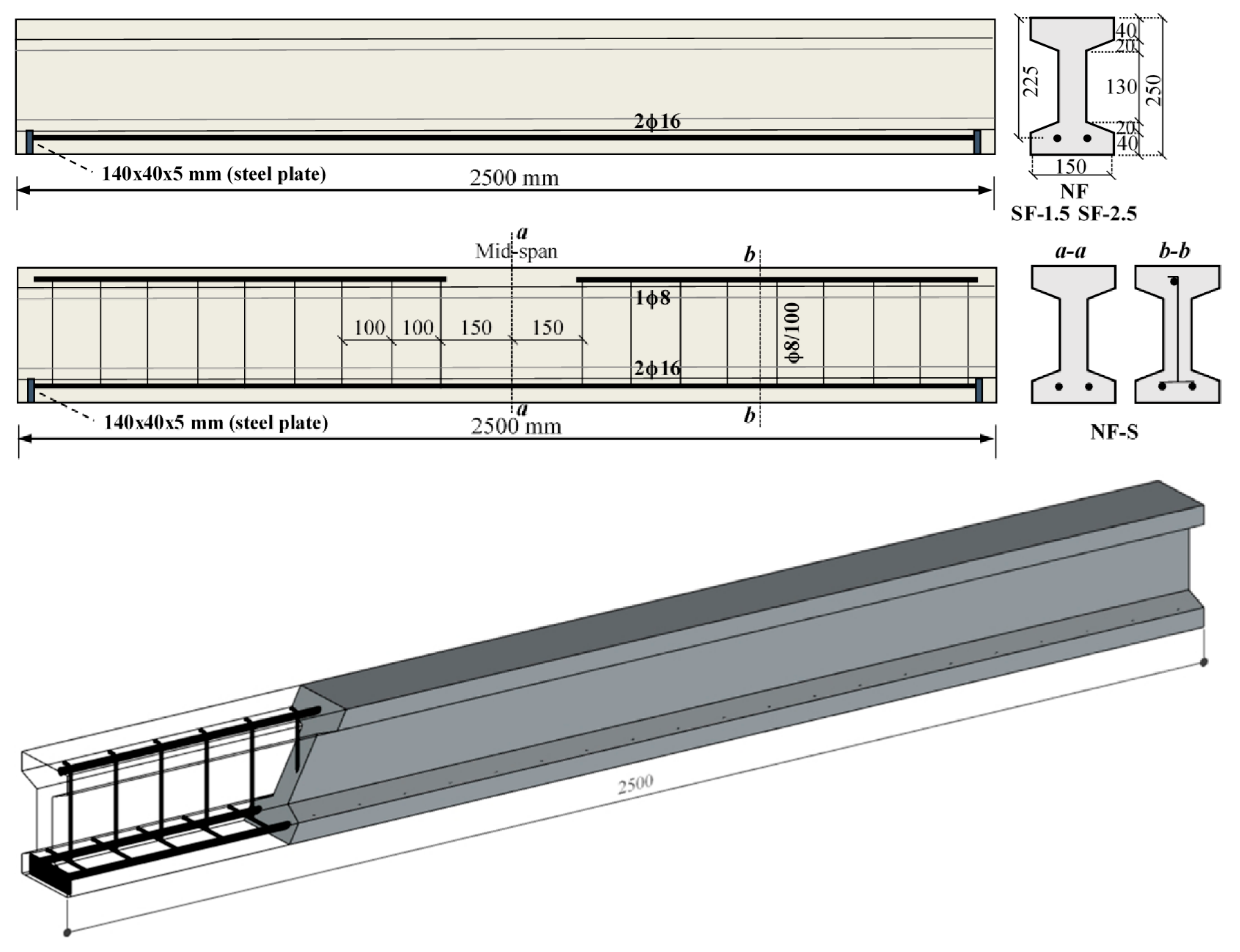
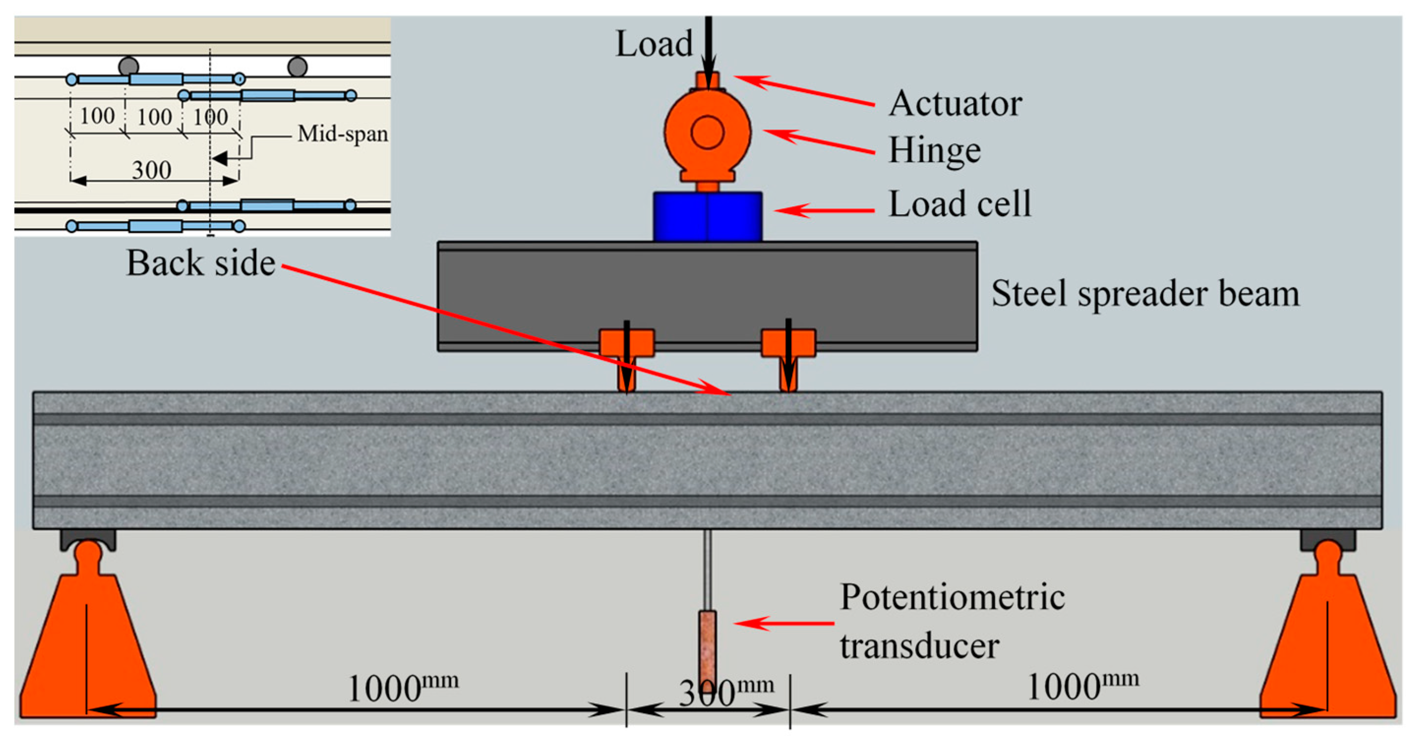
2.2. Details of Beam Specimens and Test Setup

In the experimental study, the total of four I-shaped and singly reinforced UHPC beams were produced with different configurations. While two of them were produced by the non-fiber UHPC with (NF-S) and without (NF) shear reinforcement to show the contribution of steel fiber use, the remaining beams were made from the UHP-FRC having the short straight fibers with 1.5% and 2.5% by volume. The I-shaped beam cross-sections comprised of 150 mm flange width, 60 mm flange thickness, 50 mm web thickness, and 250 mm height. The total length of beams is 2500 mm, as shown in Figure 2. The tensile reinforcement ratio was selected as 2.2%, which consisted of two deformed 16 mm reinforcing steel bars. The studied reinforcement ratio almost corresponds to the upper limits stipulated in the design codes such as TS-500 [38], ACI 318 [36], and Eurocode-2 [39]. The shear span to depth ratio was fixed to roundly 4.4 for all beams. In order to avoid the premature bond failure, the ends of tensile reinforcements were welded by a steel plate. No shear reinforcement was placed on the UHP-FRC beams to show the potential advantages of fiber use. The geometric sizes and details are expressed on a typical test beam in Figure 2. Whereas the reference beam NF without the shear reinforcement was designed to fail by shear, the beam NF-S had the shear reinforcement with 8 mm diameter and 100 mm spacing to ensure the ductile flexure failure (Figure 2). In addition, a single top rebar of 8 mm was provided to link the shear reinforcements at the shear dominant region out of the applied loads. The UHP-FRC beams were named based on the volume fraction. For instance, the SF-1.5 points out the UHP-FRC beam with the 1.5% steel fiber by volume.
The test setup for four-point loading is schematically given in Figure 3. The load was monotonically acted on by a hydraulic servo machine having the capacity of 500 kN. The loading with deflection control was conducted on a mid-span deflection rate of 0.2 mm/min up to the maximum load. Later on, the rate was increased to 0.5 mm/min to reduce the test time between the peak and ultimate deflections for the beams passing from the shear to flexure. The applied load P transferred to the test beam as two-point loads of P/2 by means of a steel spreader beam (Figure 3). The loads were applied at a distance of 1000 mm from the supports. A potentiometric transducer was placed to the bottom face of beam mid-span to obtain the load–deflection curve. In addition, a curvature meter setup was placed to the back side of beams to measure the average curvature value on a zone of 300 mm. This setup consisted of four transducers where two of them were placed to the left upper and bottom flanges of the beams and the other two were attached to the right side, as shown in Figure 3. During the tests, the load increments were stopped at the particular deflection values, and the crack formations were marked over the beams. A 24-channel data acquisition system, in which the data-recording frequency is 8 Hz per channel, was used to get the load and deflections from the test setup.

3. Test Results and Observations

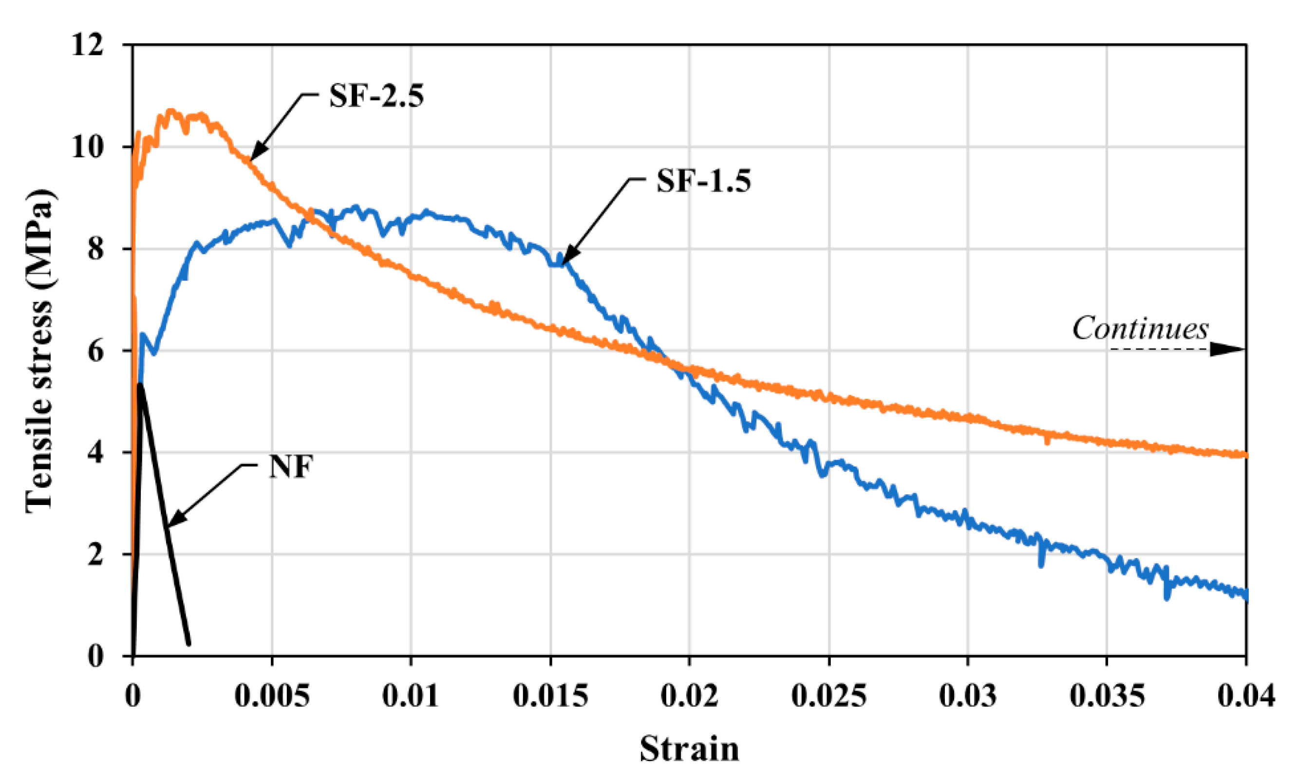
3.1. Material Test Results

The average values of concrete compressive and tensile strengths (fc’ and ft) for all concrete mixtures as well as the yield and ultimate strengths of tensile reinforcements are presented in Table 2. The results indicated that the steel fiber use increased the compressive strength by an average of 10% in comparison with the non-fiber concrete. The inclusion of 1.5 and 2.5 vol% short-straight fibers to the UHP-FRC mixtures significantly improved the tensile strength by 1.7 and 2.1 times, respectively. Even though there was no significant difference between the compressive strengths when the volume fraction increased from 1.5% to 2.5%, the tensile strength was affected by the fiber increase in a sensitive manner, as shown in Table 2.
The tensile stress–strain behaviors of concrete mixtures used in this study are presented in Figure 4 for all concrete mixtures. As expected, the brittle tensile failure occurred once the first crack formed for the NF mixture. In the UHP-FRC samples, the strain-hardening behavior was achieved after the first crack through the crack-bridging ability of steel fibers. After the peak load, the fibers began to pull out due to the growth of cracks, and the strength degradations were commenced, which reflects the initiation of the strain softening response, as shown in Figure 4.
In order to evaluate some rheological properties, the slump-flow test results (spread and t500 values) are presented in Table 2. The tests showed that the presence of steel fiber affected the flowability in a negative manner. However, the spread value decreased by an average of 8% with the fiber use comparing to the non-fiber form. It was also noted that the viscosity of concrete increased with the fiber use based on the t500 measurements.

3.2. Structural Test Results

After conducting the monotonic loadings to the NF, NF-S, and UHP-FRC beams until the failure, the load–deflection responses are presented in Figure 5. While the reference beam NF without the shear reinforcement suddenly failed without providing any deflection just after the single diagonal crack formation, the ductile flexural failure was observed for the beam NF-S, as expected at the beginning of the test.
Referring to Figure 5, the load–deflection curves linearly increased until the first cracking point, and then stiffness reduced. It can be noted that since the same concrete mixture was considered for both reference beams, the initial stiffnesses made a match of it. After the post-cracking stage, the load–deflection responses of beams divided into two groups with respect to their failure modes, as the shear or flexure. The beam NF failed by the shear with a sudden load drop before the yielding of reinforcement and produced no deflection capability. Regardless of the fiber volume fraction, full flexural behavior including the deflection hardening response commenced for the UHP-FRC beams without the shear reinforcement, as shown in Figure 5. From the beginning to the end of the tests, the UHP-FRC beams showed pretty good stabile behavior thanks to the fibers even at excessive deflection values being load drops. After this load decreases, some stability problems began to take place over the beams. Looking from the perspective of another flexural behavior, there is no deflection capacity of the beam NF-S after the maximum load due to the concrete crushing. It should be noted that the initial stiffness and load-carrying capacities of the UHP-FRC beams apparently are greater than those of the non-fiber configurations through the fibers’ crack-bridging ability. The main deflection and load values obtained from the tests are presented in Table 3. The yield deflection (Δy) was obtained from the bi-linearized load–deflection behavior, which is one of the methods recommended in Park [40]. This deflection point corresponds to the displacement at the intersection of the secant stiffness at 75% of the peak load (Pp) with the peak load level (Figure 6). Park also proposed some procedures to specify the ultimate deflection (Δu) of experimental load–deflection behavior [40]. In the current study, 20% load reduction method of these procedures was used to determine the ultimate point, as shown in Figure 6. Here, the response quantities with respect to the deflection ductility were calculated only for the NF-S and UHP-FRC beams exhibiting the ductile behavior.

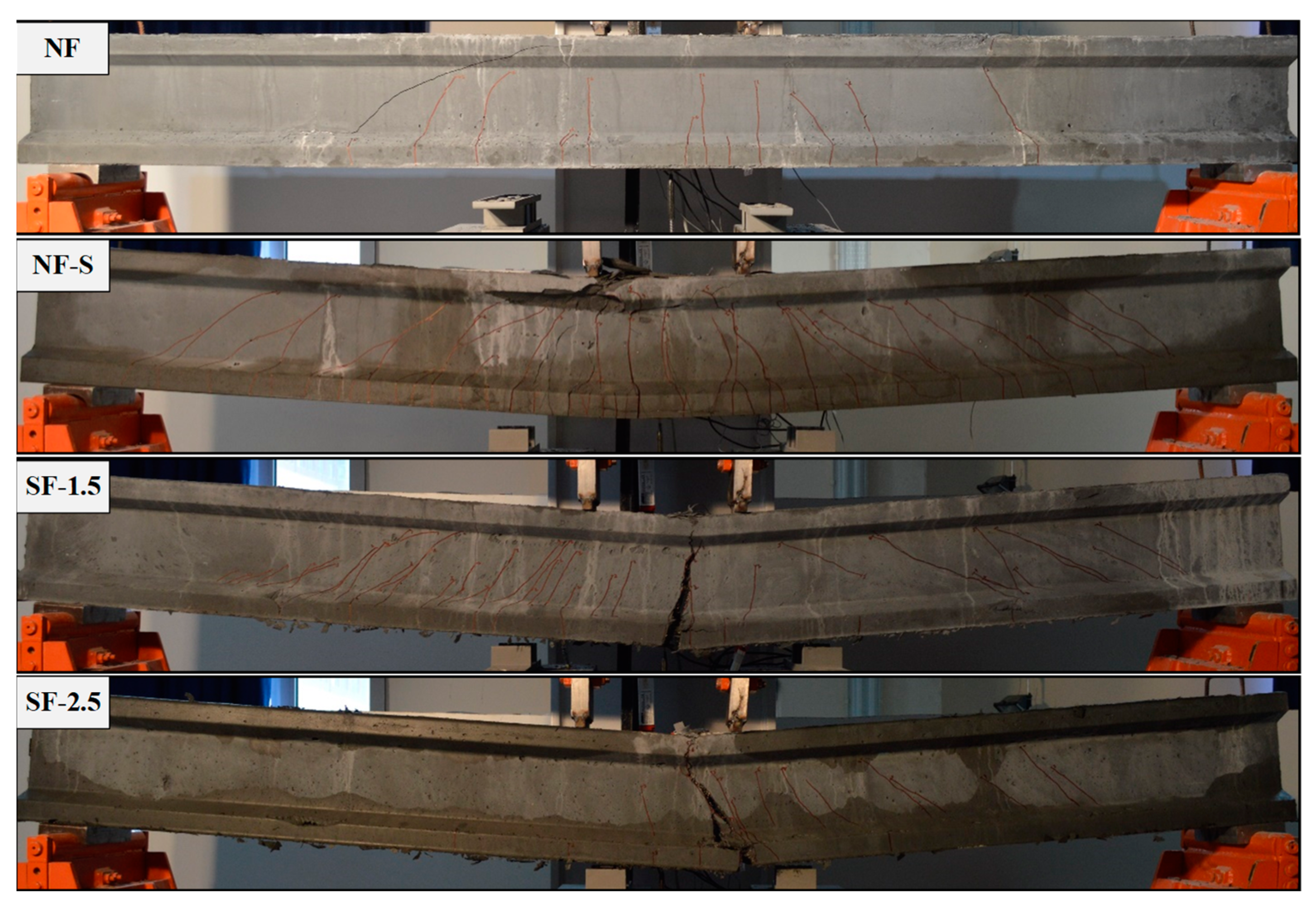
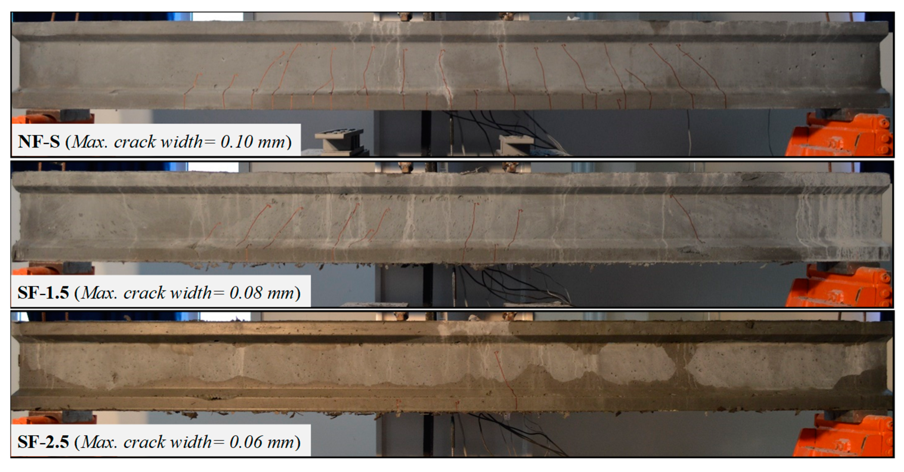
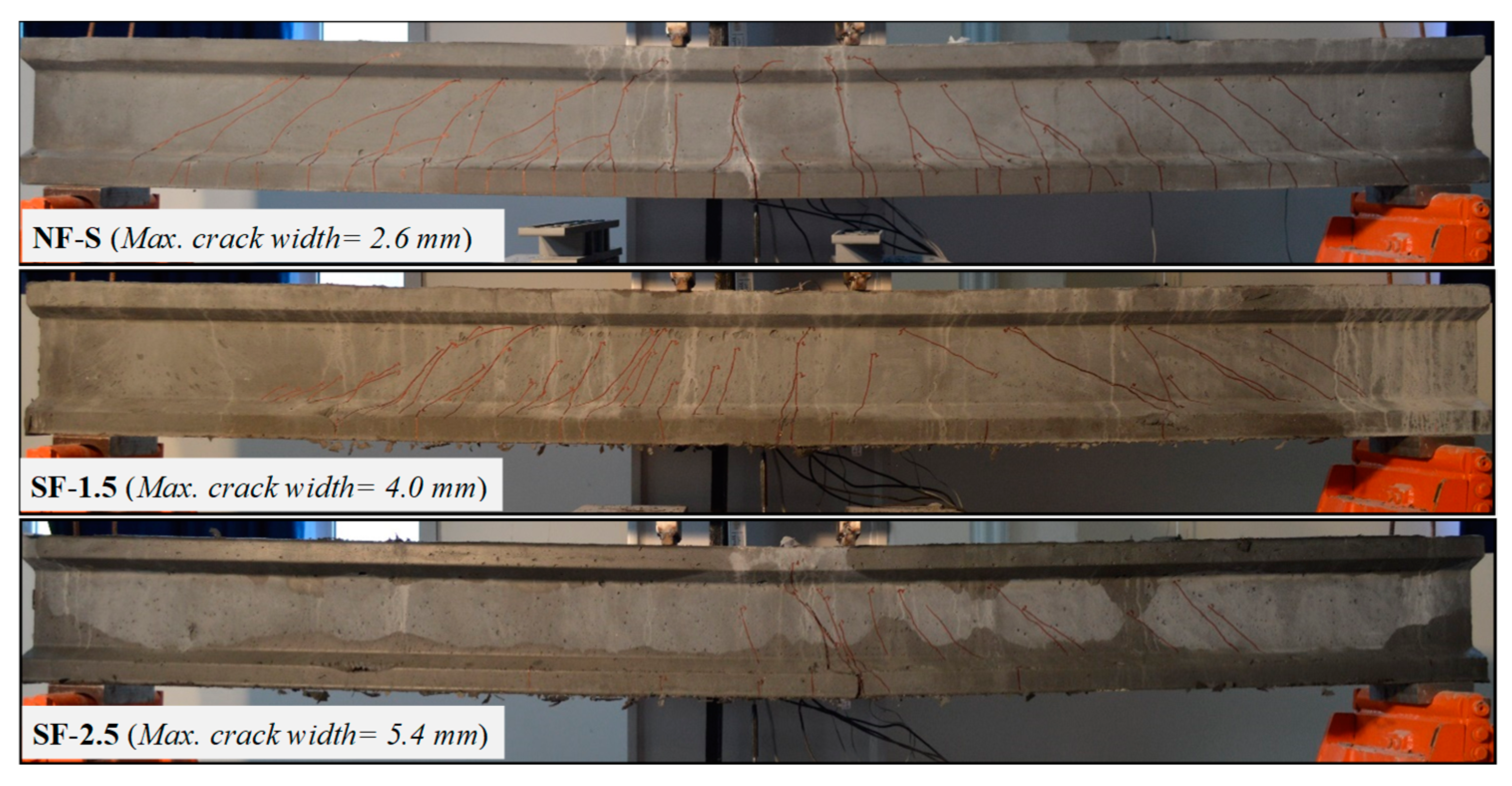
3.2.1. Cracking Behavior and Failure Modes

At the beginning of initial load increments, a large number of closely spaced microcracks developed vertically at the bottom faces in the pure moment region of beams. Note that it is not easy to see them with the naked eye until the peak load. Later on, more vertical cracks formed beside the existing cracks; together, the increasing load levels, but the crack widths remained at very low levels for the UHP-FRC beams due to the fibers’ crack-bridging ability. The failure modes of the beams are presented in Figure 7 and Table 3. When the load increased further, the reference beam NF without the shear reinforcement failed by the shear with a sudden load drop without any deflection capacity just after a single diagonal crack formation was initiated in the shear span. The related crack propagated between the left loading point and the bottom face of the beam. This failure mode pointed out is the diagonal tension failure (DT). For the second reference beam NF-S, as would be expected, the ductile flexural failure occurred since the shear reinforcements were placed to the shear-span and the tensile reinforcement ratio is below the balanced reinforcement ratio. However, the concrete crushing was observed at the compression region rather than the reinforcement rupture, and it negatively affected the deflection and curvature ductilities (Table 3).
In the case of providing adequate steel fiber content to the UHPC mixture, the fibers prevented the formation and propagation of diagonal cracks due to their crack-bridging ability, and the fiber use provided remarkable capacity to the beams. The cracking behavior of UHP-FRC beams is dissimilar when comparing to both reference beams. Here, a major crack formed at a single point over the mid-span. This crack intensely enlarged as against others due to the crack localization, as shown in Figure 7. Hence, the tensile reinforcement ruptured without the concrete crushing, even though the tensile reinforcement ratio is almost at the upper limit stipulated in the design codes. It can be noted that this crack phenomenon is distinctive, regardless of the fiber content, for the normal strength fibrous-reinforced concrete members.
Referring the conducted test results, the addition of 1.5 vol% short straight fibers to the UHPC mixture was enough to change the failure mode without requiring any shear reinforcement. This observation was well-supported with those presented in Kim et al. [22], Zagon et al. [30], Lim and Hong [31], and Hegger and Bertram [33]. It can be deduced that the steel fiber use provided a preferable structural performance for both fiber volume fractions against the reference beam exhibiting flexural behavior. This result also indicated that the inclusion of moderate-level short fibers to the UHP-FRC mixture may take the place of the shear reinforcement in practical applications.
The cracking behaviors for the test beams exhibiting the flexural failure are presented at the specific deflections of L/500 and L/100. While the value L/500 corresponds to the serviceability limit state (SLS) in the elastic region, the value L/100 represents the ultimate limit state (ULS) where significant inelastic deformations occurs. The cracking patterns and the maximum crack widths obtained from both limit states are given in Figure 8 and Figure 9. The crack widths at the SLS for the beams SF-1.5 and SF-2.5 decreased 20% and 40%, respectively. This indicates that the increases in fiber amount positively affected the limitation of cracks. However, the crack widths at the ULS for the UHP-FRC beams increased about two times due to the crack localization effect.

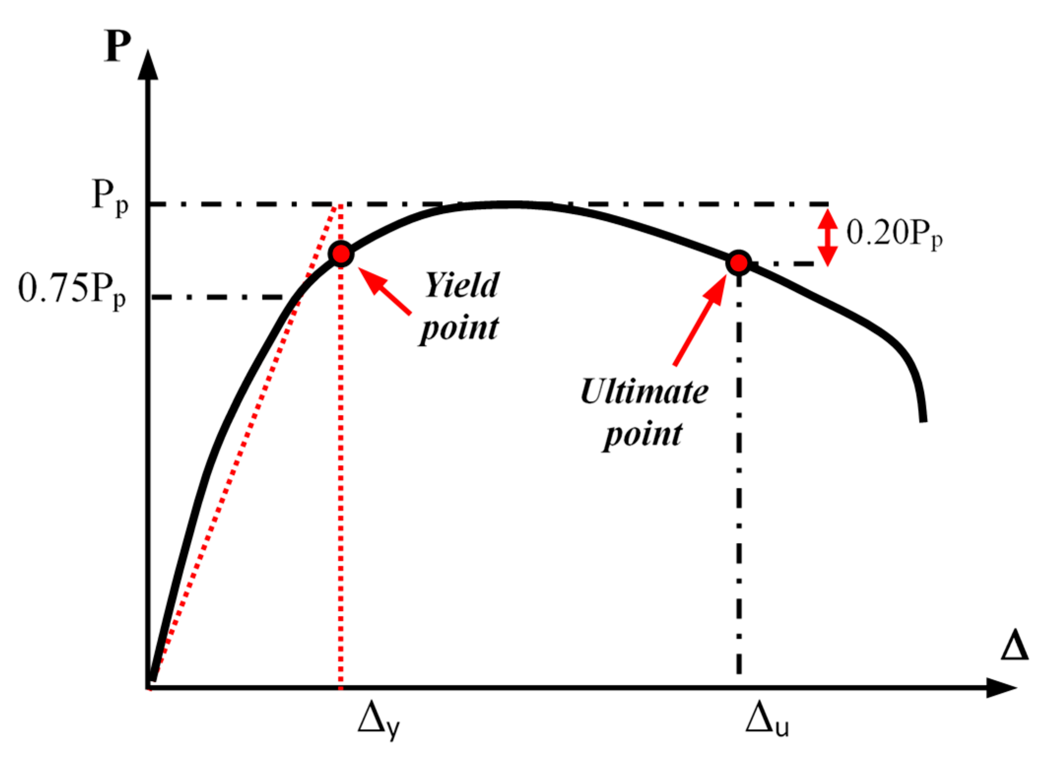
3.2.2. Deflection Ductility

For the test beams exhibiting the ductile behavior, the deflection ductilities (μΔ) were calculated by dividing the ultimate deflection (Δu) by yield deflection (Δy). In order to show the superiorities of steel fiber use from the viewpoint of the flexural behavior, the ductility values calculated for two UHP-FRC beams were compared to those of the NF-S beam. The main response quantities with respect to the deflection ductility are presented in Table 3.
Referring to Figure 5 and Table 3, the inclusion of short straight fiber to the UHPC matrix, regardless of the fiber amount, ensured much better ductility performance in comparison to the reference beam, NF-S. It was noted that the use of 1.5 and 2.5 vol% fibers improved the ductility by 1.55 and 1.80 times, respectively. The reason underlying this response is that the NF-S and UHP-FRC beams have different cracking characteristics. Although the test beams showed the ductile failure, except for the NF beam, while the NF-S beam failed by the concrete crushing after the maximum load, the reinforcement rupture for the UHP-FRC beams took place due to the major crack formed over the mid-span.

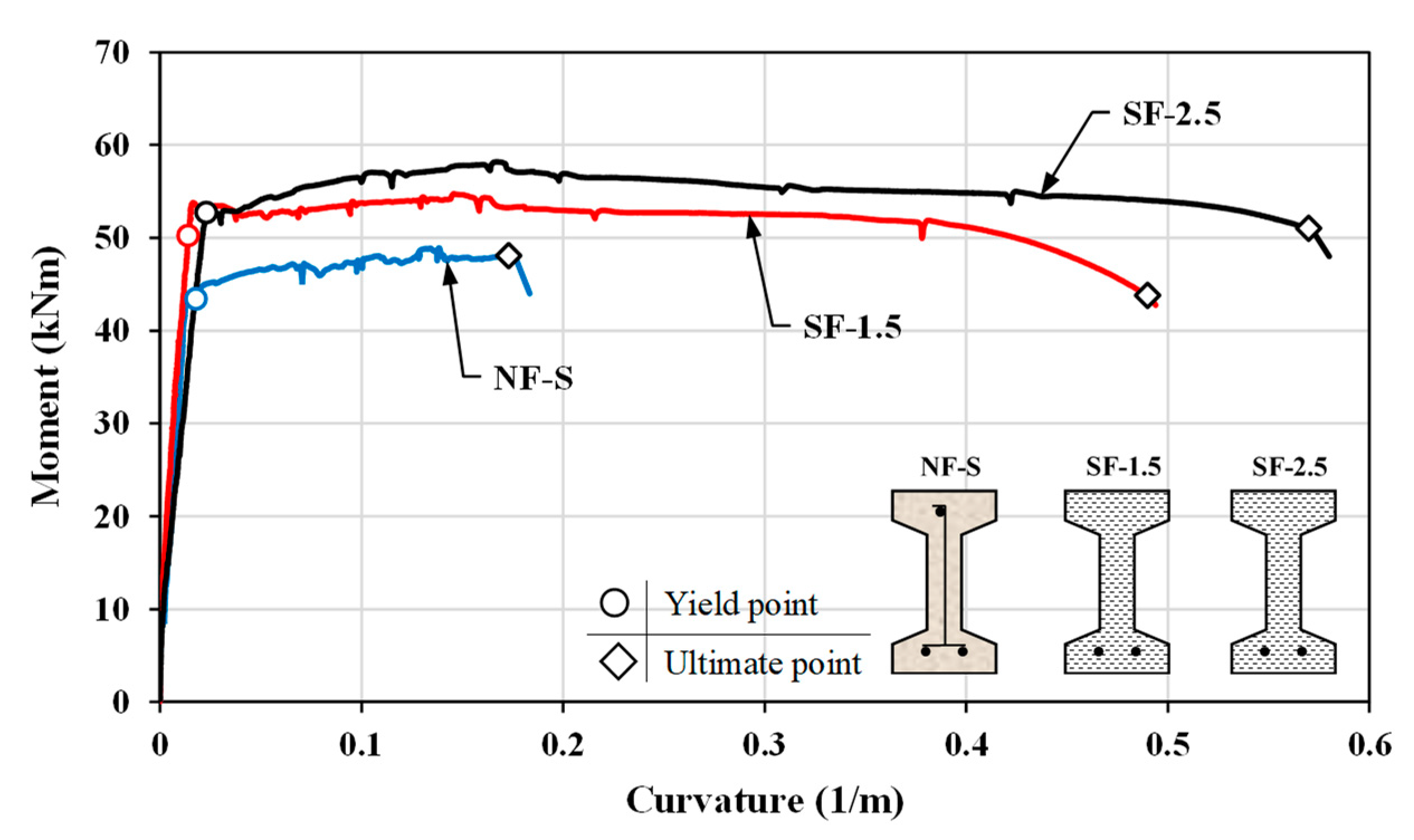
3.2.3. Curvature Ductility

On three beams exhibiting the ductile behavior, as shown in Figure 10, the moment-curvature responses were determined with the help of curvature meter setup placed to the back side of the mid-region. As in the deflection ductility, the curvature ductilities (μϕ) were calculated by dividing the ultimate curvature (ϕu) by the equivalent yield curvature (ϕy). Here, the yield curvature was captured from the bi-linearized moment-curvature graphics. The curvature ductilities and other characteristic values for the related test beams are given in Table 4.
As shown from Figure 10 and Table 4, the steel fiber uses with 1.5 and 2.5 vol% significantly improved the curvature ductility by 3.72 and 2.64 times, respectively, compared to the reference beam NF-S. It can be also noted that while the ultimate curvature of the SF-2.5 beam is greater than that of the SF-1.5 beam, the curvature ductility of the SF-1.5 beam is higher because its yield curvature is somewhat larger than that of the SF-2.5 beam. Extremely large curvature ductilities were obtained as against the deflection ductilities due to the crack localization in the UHP-FRC beams (Table 4). When the normal-strength concrete was considered instead of the UHPC, it would not be possible to obtain such great curvature ductilities because of the high tensile reinforcement ratio. Hence, the moderate-level steel fiber use in the UHP-FRC matrix demonstrates highly effective advantages in terms of the deflection and curvature ductilities.

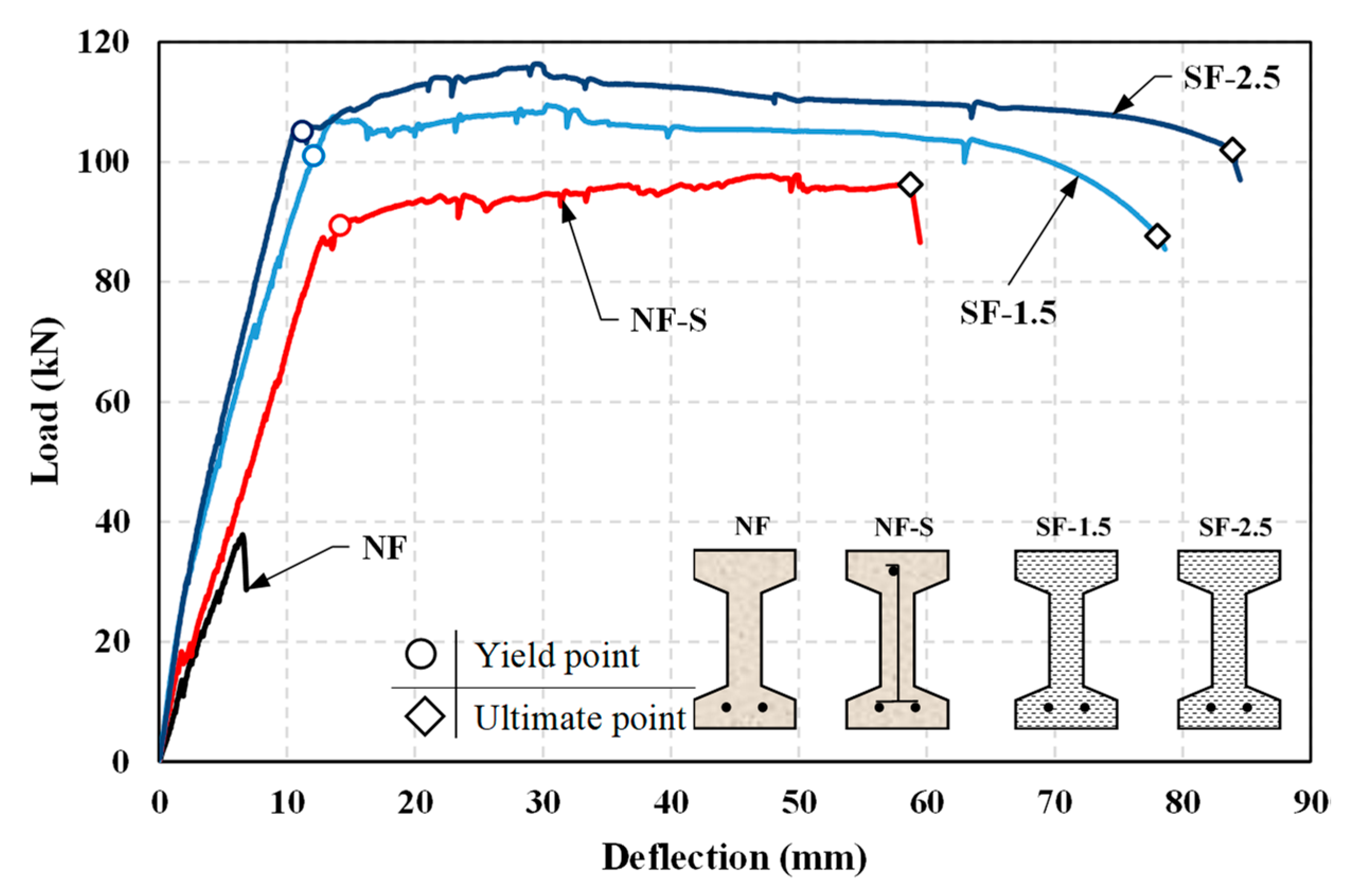
3.2.4. Load Carrying Capacity

In order to see the contribution of steel fibers on the load carrying capacities, the peak loads (Pp) of UHP-FRC beams were proportioned to that of the NF-S beam. As shown in Figure 5 and Table 3, the increases of 12% and 19% were obtained for two volume fractions by way of the fiber contribution in the compression and tensile regions. It can be noted that the fiber effectiveness on the beam’s load capacities showed an increasing tendency as the considered fiber amount increases. However, the fiber use provided exceptional contribution to the non-fiber beam without the shear reinforcement. The largest gain in the load carrying capacity was determined for the SF-2.5 beam with the highest fiber amount (Figure 5).

4. Numerical Predictions of the Shear and Flexural Capacities

Regarding the nominal shear capacity of reinforced concrete beams produced by the normal-strength concrete as well as high-strength concrete in some instances, some equations were given in well-known design codes such as ACI 318 [36], Eurocode 2 [39], and NZS 3101 [41]. These equations can be applied up to an upper limit of compressive strength. While the ACI 318 and Eurocode 2 limit as 60 and 70 MPa, respectively, the NZS 3101 based on 90 MPa. However, it is unknown whether or not the practical equations are applicable for the concretes with higher and higher compressive strength such as the UHP-FRC and reactive powder concrete. In the current study, the shear capacity of the reference beam, NF, without the shear reinforcement was calculated by different code equations, and the results were discussed by referencing the experimental capacity.
Regarding the other part, although some recommendations [1,2,4,5] were presented with regard to the flexural moment capacity of the UHP-FRC members, these approaches have not been included yet in a design code. Many efforts were conducted to practically calculate the capacities of both high strength and ultra-high strength fiber-reinforced concrete members, investigating the shape of the concrete stress block, ultimate strain capacity, fibers’ geometrical properties, volumetric ratio, orientation, and bond stress, as well as other parameters affecting the tensile stress distribution [42,43,44,45,46,47,48,49,50]. More recently, the authors of this study proposed a numerical approach to predict the nominal moment capacity of UHP-FRC beams with rectangular cross-sections [14]. In the second part of the numerical investigations, the flexural capacity of the test beams, except for the NF beam, were numerically determined and compared with the experimental results.

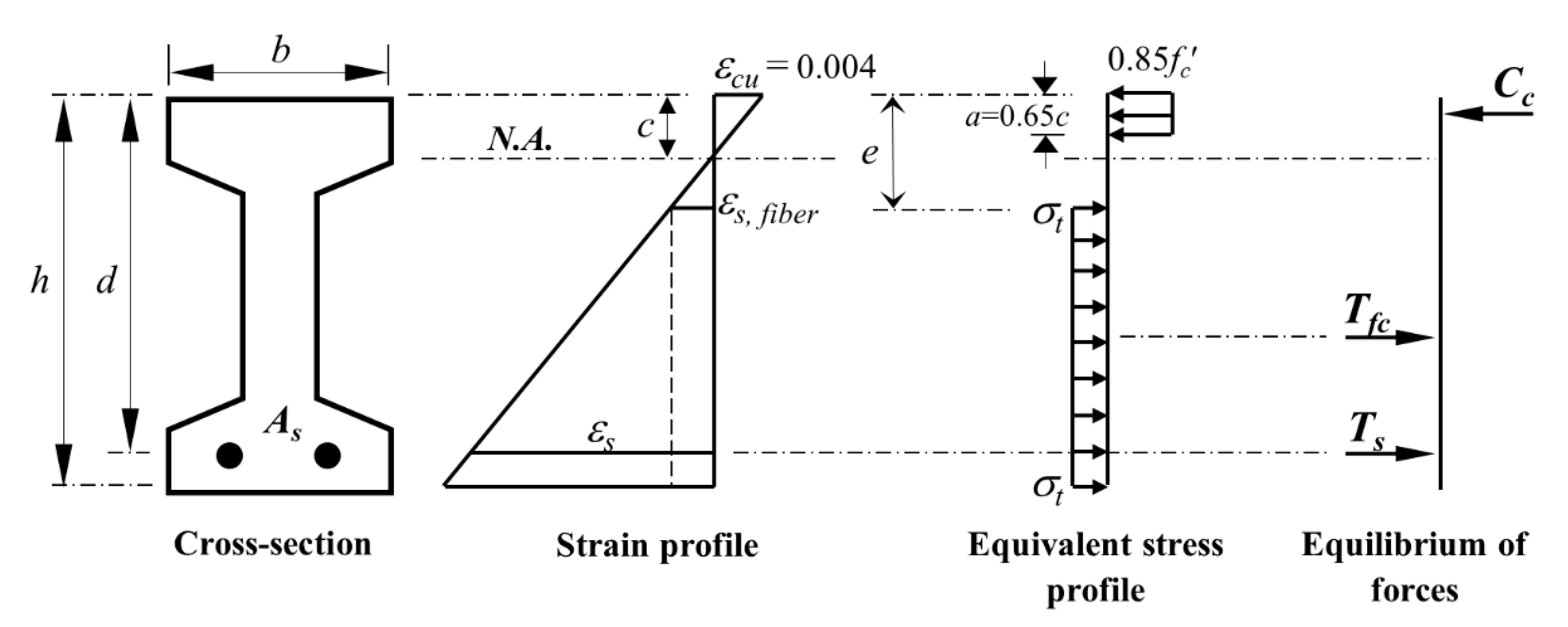
4.1. Predicting the Nominal Shear Capacity

As noted above, the nominal shear strength of the NF test beam without the shear reinforcement was calculated by means of Equations (1)–(3), which are given in the ACI 318, Eurocode 2, and NZS 3101, respectively. In Equation (1), ρ denotes the longitudinal reinforcement ratio; a, d, and bw are the shear span, effective depth, and width of the beam, respectively. In Equation (2), k is the size factor (=1 + (200/d)0.5). In Equation (3a,b), kd represents the influence of the member depth on the shear strength. If d ≤400 mm, kd = 1.0; d >400 mm, kd = (400/d)0.25. ka is an impact factor for the maximum aggregate size (da). If da ≥20 mm, ka = 1.0; if da ≤10 mm, ka = 0.85. Note that the d should be in mm in calculation of the coefficients k and kd. The value of Vc can be calculated by the linear interpolation for 200 mm < d < 400 mm.
ACI   318   :   V n = [ f c + 120 ρ ( d a ) ] b w d 7   ( M P a )
Eurocode   2   :   V R d , c = [ 0.18 k ( 100 ρ f c ) 1 / 3 ] b w d   ( M P a )
NZS   3101 :   V c = k d k a v b b w d d 400   m m   ( M P a )
V c = m a x [ E q . ( 3 a ) ; 0.17 k a f c b w d   ] d 200   m m
v b = m i n [ ( 0.07 + 10 ρ ) f c   ; 0.2 f c   ] 0.08 f c
In Table 5, the calculated shear capacities (Vncal) were proportioned to the experimental capacities (Vnexp) to show how the code equations give results. It can be noted that while the ACI 318 and NZS 3101 codes gave pretty good results, the Eurocode 2 equation highly overestimated the shear strength with an error of 42% (Table 5). Although the ACI 318 and NZS 3101 approaches are in different forms, both equations gave close predictions of the shear strength. It can be thought that these equations may be used to determine the shear capacities of UHPC beams. However, the shear equation of Eurocode 2 should be improved by considering the mechanical properties of this type of special concrete.

4.2. Predicting of the Flexural Moment Capacity

The flexural design principles developed for the normal-strength concrete cannot be directly applied to the UHP-FRC members since the compressive, tensile, and strain-hardening behaviors are distinct from those of the conventional concrete. In the scope of numerical investigations, an approach proposed by the authors [14] was used to predict the nominal moment capacity of UHP-FRC beams. Working together with this model, the use of a well-known equivalent stress block was maintained for the compression and tension regions, as shown in Figure 11. The tensile strength of the UHP-FRC beams were obtained from the direct tensile test in order to eliminate uncertainties in determining the fiber parameters. However, the tensile strengths (σt exp) must be reduced by a coefficient to get an equivalent tensile block as in the compression block (Figure 11). In this context, the strength reduction factor (k) was optimized to 0.75, as shown in Equation (4).
σt = k σtexp
The approach was applied to the NF-S and UHP-FRC test beams, and the calculated moment capacities (Mpcal) were proportioned to the experimental capacities (Mpexp), as shown in Table 6. It is apparent that the numerical results belonging to the UHP-FRC beams for both fiber amounts are highly compatible with the test results since the errors are in a band less than 10%. However, the non-fiber beam’s capacity was underestimated at a relative error of 15%. It can be deduced that the practical approach can satisfyingly determine the flexural moment capacities of UHP-FRC beams.

5. Conclusions

In the presented experimental study, the feasibility of steel fibers in place of shear reinforcement in the UHPC beams and the advantages of steel fiber use without providing any shear reinforcement were investigated in terms of flexural behavior. For these purposes, the total of four I-shaped test beams consisting of the non-fiber UHPC beams with/without the shear reinforcement and the UHP-FRC beams, including the short straight-fibers with 1.5% and 2.5% by volume, were produced. The shear and flexural test results were discussed based on the non-fiber UHPC beam configurations. In addition, the relation between the well-known code equations and the nominal shear capacity was discussed by referencing the experimental result. For the test beam exhibiting the flexural behavior, the moment capacities of UHP-FRC beams were numerically determined and compared with the experimental results as well. The following outcomes can be deduced from the experimental and numerical investigations.
The NF beam failed by the shear with a sudden load drop before the yielding of reinforcement and produced no deflection capability. Regardless of the fiber volume fraction, full flexural behavior commenced for the UHP-FRC beams without the shear reinforcement. On the other hand, the initial and effective stiffnesses of the UHP-FRC beams are apparently greater than those of the non-fiber configurations through the fibers’ crack-bridging ability. The cracking behavior for UHP-FRC beams is dissimilar when comparing to the non-fiber beams. A major crack formed at a single point over the beam mid-span. This crack is intensely enlarged against others due to the crack localization. Thus, the reinforcement ruptured without the concrete crushing even though the considered tensile reinforcement ratio is almost at the upper limit stipulated in the design codes.
The steel fiber use with 1.5% and 2.5% by volume improved the deflection ductility by 1.55 and 1.80 times, respectively, in comparison to the shear reinforcement. However, extremely large curvature ductilities for the UHP-FRC beams were obtained in comparison to the deflection ductilities. When the normal-strength concrete was considered instead of the UHPC, it would not be possible to obtain such great curvature ductilities because of the high tensile reinforcement ratio. The fiber use provided exceptional contribution to the non-fiber beams with and without the shear reinforcement. The largest gain in the load carrying capacity was determined for the test beam with the highest fiber amount.
The test results indicated that the steel fiber use ensured highly effective advantages in terms of the flexural behavior. Even though no shear reinforcement is provided in the UHP-FRC beams, in contrast with the requirements in design codes, the inclusion of steel fiber use of 1.5% by volume is sufficient to guarantee the flexural behavior. This observation consisted with those deduced from the researches by others [22,30,31,33].
Although the ACI 318 and NZS 3101 approaches are in different forms as well as are based on the normal-strength concrete, both equations predict the shear capacity satisfyingly. However, the Eurocode 2 equation highly overestimated the shear strength with an error of 42%. On the other side, the previously proposed approach by the authors is highly compatible with the test results of UHP-FRC beams.

Author Contributions

Conceptualization and methodology, U.H., A.Y., and K.T.; experiments and interpreted the data, U.H. and K.T.; validation, T.B. and K.T.; writing—original draft preparation, U.H.; writing—review and editing, supervision, U.H. and T.B.; project administration, A.Y. and T.B.; funding acquisition, A.Y.

Funding

This research was funded by the Scientific and Technological Research Council of Turkey (TUBITAK), Project No.: 116M517.

Conflicts of Interest

The authors declare no conflict of interest.

References

  1. Fehling, E.; Schmidt, M.; Walraven, J.; Leutbecher, T.; Frönlich, S. Ultra-High Performance Concrete UHPC: Fundamentals, Design, Examples, Beton-Kalender; Wilhelm Ernst & Sohn: Berlin, Germany, 2014. [Google Scholar]
  2. AFGC/SETRA. Recommendation: Ultra High Performance Fibre-Reinforced Concretes, Revised ed.; Association Française de Génie Civil, Service D’études Techniques Des Routes et Autoroutes; AFGC Publication: Paris, France, 2013. [Google Scholar]
  3. JSCE. Recommendations for Design and Construction of Ultra-High Strength Fiber Reinforced Concrete Structures; JSCE Guidelines for Concrete No. 9; Japan Society of Civil Engineers: Tokyo, Japan, 2006. [Google Scholar]
  4. JSCE. Recommendations for Design and Construction of High Performance Fiber Reinforced Cement Composites with Multiple Fine Cracks (HPFRCC); Concrete Engineering Series 82; Japan Society of Civil Engineers: Tokyo, Japan, 2008. [Google Scholar]
  5. Russell, H.G.; Graybeal, B.A. Ultra-High Performance Concrete: A State-of-the-Art Report for the Bridge Community; HWA-HRT-13-060, U.S.; Federal Highway Administration: McLean, VA, USA, 2013.
  6. Habel, K.; Gauvreau, P. Response of ultra-high performance fiber reinforced concrete (UHPFRC) to impact and static loading. Cem. Concr. Compos. 2008, 30, 938–946. [Google Scholar] [CrossRef]
  7. Wille, K.; Naaman, A.E.; Parra-Montesinos, G.J. Ultra-high performance concrete with compressive strength exceeding 150 MPa (22 ksi): A simpler way. ACI Mater. J. 2011, 108, 46–54. [Google Scholar]
  8. Wille, K.; Naaman, A.E.; El-Tawil, S.; Parra-Montesinos, G.J. Ultra-high performance concrete and fiber reinforced concrete: Achieving strength and ductility without heat curing. Mater. Struct. 2012, 45, 309–324. [Google Scholar] [CrossRef]
  9. Wille, K.; Parra-Montesinos, G.J. Effect of beam size, casting method, and support conditions on flexural behavior of ultra-high-performance fiber-reinforced concrete. ACI Mater. J. 2012, 379–388. [Google Scholar]
  10. Hussein, L.; Amleh, L. Size effect of ultra-high performance fiber reinforced concrete composite beams in shear. Struct. Concr. 2018, 19, 141–151. [Google Scholar] [CrossRef]
  11. Park, J.J.; Kang, S.T.; Koh, K.T.; Kim, S.W. Influence of the Ingredients on the Compressive Strength of UHPC as A Fundamental Study to Optimize the Mixing Proportion. In Proceedings of the Second International Symposium on Ultra High Performance Concrete, Kassel, Germany, 5–7 March 2008; pp. 105–112. [Google Scholar]
  12. Yoo, D.Y.; Lee, J.H.; Yoon, Y.S. Effect of fiber content on mechanical and fracture properties of ultra high performance fiber reinforced cementitious composites. Compos. Struct. 2013, 106, 742–753. [Google Scholar] [CrossRef]
  13. Kim, D.J.; Park, S.H.; Ryu, G.S.; Koh, K.T. Comparative flexural behavior of hybrid ultra high performance fiber reinforced concrete with different macro fibers. Constr. Build. Mater. 2011, 25, 4144–4155. [Google Scholar] [CrossRef]
  14. Turker, K.; Hasgul, U.; Birol, T.; Yavas, A.; Yazici, H. Hybrid fiber use on flexural behavior of ultra high performance fiber reinforced concrete beams. Compos. Struct. 2019, 229, 111400. [Google Scholar] [CrossRef]
  15. Hasgul, U.; Turker, K.; Birol, T.; Yavas, A. Flexural behavior of ultra-high-performance fiber reinforced concrete beams with low and high reinforcement ratios. Struct. Concr. 2018, 19, 1577–1590. [Google Scholar] [CrossRef]
  16. Turker, K.; Birol, T.; Yavas, A.; Hasgul, U.; Yazici, H. Flexural behavior of beams with ultra high performance fiber reinforced concrete. Tech. J. 2019, 30, 8777–8801. [Google Scholar]
  17. Yavas, A.; Hasgul, U.; Turker, K.; Birol, T. Effective fiber type investigation on the shear behavior of ultrahigh-performance fiber-reinforced concrete beams. Adv. Struct. Eng. 2019, 22, 1591–1605. [Google Scholar] [CrossRef]
  18. Baby, F.; Marchand, P.; Toutlemonde, F. Shear behavior of ultrahigh performance fiber-reinforced concrete beams. I: Experimental investigation. J. Struct. Eng. 2014, 140, 04013112. [Google Scholar] [CrossRef]
  19. El-Dieb, A.S.; El-Maaddawy, T.A.; Al-Rawashdah, O. Shear Behavior of Ultra-High-Strength Steel Fiber Reinforced Self-Compacting Concrete Beams. In Proceedings of the First International Conference on Construction Materials and Structures, Johannesburg, South Africa, 24–26 November 2014; pp. 972–979. [Google Scholar]
  20. Tahenni, T.; Chemrouk, M.; Lecompte, T. Effect of steel fibers on the shear behavior of high strength concrete beams. Constr. Build. Mater. 2016, 105, 14–28. [Google Scholar] [CrossRef]
  21. Qi, J.-N.; Ma, Z.J.; Wang, J.-Q.; Liu, T.-X. Post-cracking shear strength and deformability of HSS-UHPFRC beams. Struct. Concr. 2016, 17, 1033–1046. [Google Scholar] [CrossRef]
  22. Kim, C.-G.; Lee, H.; Park, H.-G.; Hong, G.-H.; Kang, S.-M. Effect of steel fibers on minimum shear reinforcement of high-strength concrete beams. ACI Struct. J. 2017, 114, 1109–1119. [Google Scholar] [CrossRef]
  23. Pourbaba, M.; Joghataie, A. Shear behavior of ultra-high performance concrete. Constr. Build. Mater. 2018, 183, 554–564. [Google Scholar] [CrossRef]
  24. Mészöly, T.; Randl, N. Shear behavior of fiber-reinforced ultra-high performance concrete beams. Eng. Struct. 2018, 168, 119–127. [Google Scholar] [CrossRef]
  25. Yoo, D.Y.; Yang, J.M. Effects of stirrup, steel fiber, and beam size on shear behavior of high strength concrete beams. Cem. Concr. Compos. 2018, 87, 137–148. [Google Scholar] [CrossRef]
  26. Zhao, J.; Liang, J.; Chu, L.; Shen, F. Experimental study on shear behavior of steel fiber reinforced concrete beams with high-strength reinforcement. Materials 2018, 11, 1682. [Google Scholar] [CrossRef] [Green Version]
  27. Ciprian, T.; Dan, B.; Victor, V.; Cornelia, M. Ultra high performance fiber reinforced concrete I beams subjected to shear action. ACTA Tech. Napoc. Civ. Eng. Archit. 2012, 55, 121–126. [Google Scholar]
  28. Voo, Y.L.; Poon, W.K.; Foster, S.J. Shear strength of steel fiber-reinforced ultra high-performance concrete beams without stirrups. J. Struct. Eng. 2010, 136, 1393–1400. [Google Scholar] [CrossRef]
  29. Kamal, M.M.; Safan, M.A.; Etman, Z.A.; Salama, R.A. Behavior and strength of beams cast with ultra high strength concrete containing different types of fibers. HBRC J. 2014, 10, 55–63. [Google Scholar] [CrossRef] [Green Version]
  30. Zagon, R.; Matthys, S.; Kiss, Z. Shear behaviour of SFR-UHPC I-shaped beams. Constr. Build. Mater. 2006, 124, 258–268. [Google Scholar] [CrossRef]
  31. Lim, W.Y.; Hong, S.G. Shear tests for ultra-high performance fiber reinforced concrete (UHPFRC) beams with shear reinforcement. Int. J. Concr. Struct. M. 2016, 10, 177–188. [Google Scholar] [CrossRef] [Green Version]
  32. Ngo, T.T.; Park, J.K.; Pyo, S.; Kim, D.J. Shear resistance of ultra-high-performance fiber-reinforced concrete. Constr. Build. Mater. 2017, 151, 246–257. [Google Scholar] [CrossRef]
  33. Hegger, J.; Bertram, G. Shear Carrying Capacity of Ultra-High Performance Concrete Beams. Tailor Made Concrete Structures; Walraven, J.C., Stoelhorst, D., Eds.; Taylor & Francis Group: London, UK, 2008; pp. 341–347. [Google Scholar]
  34. Yang, I.H.; Kim, B.S.; Joh, C. Shear behaviour of ultra-high performance fibre-reinforced concrete beams without stirrups. Mag. Concr. Res. 2012, 64, 979–993. [Google Scholar] [CrossRef]
  35. Model Code 2010. Fib Model Code for Concrete Structures 2010; International Federation for Structural Concrete; Wilhelm Ernst & Sohn: Berlin, Germany, 2013. [Google Scholar]
  36. ACI 318. Building Code Requirements for Structural Concrete (ACI 318M-14) and Commentary (318R-14); American Concrete Institute: Farmington Hills, MI, USA, 2014. [Google Scholar]
  37. Yoo, D.-Y.; Yuan, T.; Yang, J.M.; Yoon, Y.S. Feasibility of replacing minimum shear reinforcement with steel fibers for sustainable high-strength concrete beams. Eng. Struct. 2017, 147, 207–222. [Google Scholar] [CrossRef]
  38. TS-500. Requirements for Design and Construction of Reinforced Concrete Structures; Turkish Standards Institution: Ankara, Turkey, 2000. [Google Scholar]
  39. EN 1992-1-1. Eurocode 2: Design of Concrete Structures—Part 1–1: General Rules and Rules for Buildings; European Committee for Standardization: Brussels, Belgium, 2004. [Google Scholar]
  40. Park, R. Evaluation of ductility of structures and structural assemblages from laboratory testing. Bull. N. Z. Natl. Soc. Earthqu. Eng. 1989, 22, 155–166. [Google Scholar]
  41. NZS 3101. Concrete Structures Standard—Part 1: The Design of Concrete Structures; The Earthquake Commission (EQC) and Department of Building and Housing (DBH): Wellington, New Zealand, 2006.
  42. Dancygier, A.N.; Savir, Z. Flexural behavior of HSFRC with low reinforcement ratios. Eng. Struct. 2006, 28, 1503–1512. [Google Scholar] [CrossRef]
  43. Yang, I.H.; Joh, C.; Kim, B.S. Flexural strength of large-scale ultra high performance concrete prestressed T-beams. Can. J. Civ. Eng. 2011, 38, 1185–1195. [Google Scholar] [CrossRef]
  44. Qi, J.; Wang, J.; John, Z. Flexural response of high-strength steel-ultra-high-performance fiber reinforced concrete beams based on a mesoscale constitutive model: Experiment and theory. Struct. Concr. 2018, 19, 719–734. [Google Scholar] [CrossRef]
  45. Chen, S.; Zhang, R.; Jia, L.J.; Wang, J.Y. Flexural behaviour of rebar-reinforced ultrahigh-performance concrete beams. Magn. Concr. Res. 2018, 70, 997–1015. [Google Scholar] [CrossRef]
  46. Khalil, W.; Tayfur, Y.R. Flexural strength of fibrous ultra high performance reinforced concrete beams. ARPN J. Eng. Appl. Sci. 2013, 8, 200–214. [Google Scholar]
  47. Imam, M.; Vandewalle, L.; Mortelmans, F. Shear-moment analysis of reinforced high strength concrete beams containing steel fibres. Can. J. Civ. Eng. 1995, 22, 462–470. [Google Scholar] [CrossRef]
  48. Xia, J.; Chanb, T.; Mackieb, K.R.; Saleemc, M.A.; Mirmiran, A. Sectional analysis for design of ultra-high performance fiber reinforced concrete beams with passive reinforcement. Eng. Struct. 2018, 160, 121–132. [Google Scholar] [CrossRef]
  49. Lim, T.Y.; Paramasivam, P.; Lee, S.L. Shear and moment capacity of reinforced steel fiber concrete beams. Magn. Concr. Res. 1987, 39, 148–160. [Google Scholar] [CrossRef]
  50. Bae, B.I.; Choi, H.K.; Choi, C.S. Flexural strength evaluation of reinforced concrete members with ultra high performance concrete. Adv. Mater. Sci. Eng. 2016, 2016, 1–10. [Google Scholar] [CrossRef] [Green Version]
Figure 1. The UHP-FRC mixing procedure, (ad) the blending steps of mixture.
Applsci 09 05526 g001
Figure 2. The geometric size and details of test beams.
Applsci 09 05526 g002
Figure 3. The four-point loading setup.
Applsci 09 05526 g003
Figure 4. The average tensile stress–strain curves for each fiber volume fraction.
Applsci 09 05526 g004
Figure 5. The load–deflection responses of test beams.
Applsci 09 05526 g005
Figure 6. Definitions of yield and ultimate points [40].
Applsci 09 05526 g006
Figure 7. The failure modes of test beams.
Applsci 09 05526 g007
Figure 8. Cracking patterns and maximum crack widths at the serviceability limit state (SLS).
Applsci 09 05526 g008
Figure 9. Cracking patterns and maximum crack widths at the ultimate limit state (ULS).
Applsci 09 05526 g009
Figure 10. The moment-curvature responses of test beams.
Applsci 09 05526 g010
Figure 11. The strain and stress distributions in relation to the numerical model.
Applsci 09 05526 g011
Table 1. The material quantities for ultra-high performance concrete (UHPC) and ultra-high performance fiber reinforced concrete (UHP-FRC) mixtures. C: cement, GGBS: ground granulated blast-furnace slag, SF: silica fume, SP: superplasticizer, W: water.
Beam NameVf (%)CSFGGBSQSWSP
(kg/m3)
NF and NF-S0.072024024089020423.0
SF-1.51.572024024085220423.6
SF-2.52.572024024082520424.3
Table 2. The mechanical properties of the reinforcement and concrete.
Beam
Name
ReinforcementConcrete
fy (MPa)fu (MPa)fc’ (MPa)ft (MPa)Slump Flow
Spread (mm)t500 (s)
NF4695901455.37802.0
NF-S4705911425.1
SF-1.54705911548.87303.0
SF-2.547359315910.77003.0
fy: yield strength, fu: ultimate strength, fc’: compressive strength, ft: tensile strength.
Table 3. The main test results for load–deflection responses.
Beam
Name
Yield Deflection Δy (mm)Peak Load Pp (kN)Ultimate Deflection Δu (mm)Ultimate Load Pu (kN)Deflection Ductility μΔ = ΔuyFailure Mode/Reason
NF-37.82---Shear/diagonal tension
NF-S14.1197.8158.7396.184.16Flexure/concrete crushing
SF-1.512.09109.5378.0287.636.45Flexure/reinforcement rupture
SF-2.511.20116.4083.89102.017.49Flexure/reinforcement rupture
Table 4. The summary of variables related to the curvature ductilities.
Beam NameYield Curvature ϕy (1/m)Peak Moment Mp (kNm)Ultimate Curvature ϕu(1/m)Ultimate Moment Mu (kNm)Curvature Ductility μϕ = ϕuyEffective Stiffness EIe = Mpy (kNm2)
NFNA18.9NANANANA
NF-S0.01848.90.1748.19.42715
SF-1.50.01454.80.4943.835.03899
SF-2.50.02358.20.5751.024.82510
Table 5. Numerical shear capacities on the reference beam NF.
Design Code Vnexp (kN)Vncal (kN)Vncal/Vnexp
ACI 318 [36]18.9120.311.07
Eurocode 2 [39]18.9126.881.42
NZS 3101 [41]18.9120.441.08
Table 6. Numerical analysis results of the NF-S and UHP-FRC beams.
Beam NameMpexp (kNm)Mpcal (kNm)Mpcal/Mpexp
NF-S48.941.50.85
SF-1.554.858.31.06
SF-2.558.262.21.07

