Article

Influence of Cracking on Oxygen Transport in UHPFRC Using Stainless Steel Sensors

1
Interuniversity Research Institute for Molecular Recognition and Technological Development (IDM), Universitat Politècnica de València, Universitat de València, 46022 Valencia, Spain
2
Institute of Science and Concrete Technology (ICITECH), Universitat Politècnica de València, 46022 Valencia, Spain
3
Department of Architectural Constructions, Universitat Politècnica de València, 46022 Valencia, Spain
*
Author to whom correspondence should be addressed.
Appl. Sci. 2020, 10(1), 239; https://doi.org/10.3390/app10010239
Submission received: 29 November 2019 / Revised: 20 December 2019 / Accepted: 25 December 2019 / Published: 28 December 2019
(This article belongs to the Special Issue Fiber-Reinforced Concrete)

Abstract

:
Reinforced concrete elements frequently suffer small cracks that are not relevant from the mechanical point of view, but they can be an entrance point for aggressive agents, such as oxygen, which could initiate the degradation processes. Fiber-Reinforced Concrete and especially Ultra High Performance Concrete increase the multi-cracking behavior, reducing the crack width and spacing. In this work, the oxygen availability of three types of concrete was compared at similar strain levels to evaluate the benefit of multi-cracking in the transport of oxygen. The types of concrete studied include traditional, High-Performance, and Ultra-High-Performance Fiber-Reinforced Concrete with and without nanofibers. To this purpose, reinforced concrete beams sized 150 × 100 × 750 mm3 were prepared with embedded stainless steel sensors that were located at three heights, which have also been validated through this work. These beams were pre-cracked in bending up to fixed strain levels. The results indicate that the sensors used were able to detect oxygen availability due to the presence of cracks and the detected differences between the studied concretes. Ultra High Performance Concrete in the cracked state displayed lower oxygen availability than the uncracked High Performance Concrete, demonstrating its potential higher durability, even when working in cracked state, thanks to the increased multi-cracking response.

1. Introduction

Model Code 2010 defines fiber reinforced concrete (FRC) as a composite material that is characterized by cement matrix (concrete or mortar) and discontinuous discrete fibers, which can be made of steel, polymers, carbon, glass, or natural materials [1]. Cracks in reinforced concrete structures are the main entrance point for aggressive agents that could initiate the degradation processes in the structure. The incorporation of fibers into the cementitious matrix can improve its durability behavior due to the reduction of crack width and the spacing of the cracks produced by the internal redistribution of stresses. The dosage, type, and geometry of the fibers will modify the crack pattern and, in general, high fiber content will lead to multiple micro-cracking with reduced spacing between cracks, instead of localized macro-cracks spaced apart several centimeters.
Ultra-High-Performance Fiber-Reinforced Concrete (UHPFRC) is a type of FRC with compressive strength between 140–200 MPa and tensile strength between 7–15 MPa [2]. This type of concrete has very low maximum particle size (1–2 mm) and well graded aggregates, high content of fibers, usually steel fibers, and it displays high ductility, producing very thin cracks under load (<60 μm). The durability performance of UHPFRC is excellent, due to its high matrix density and its multi-cracking behavior that is provided by the fibers [3]. Other FRC families, such as Strain Hardening Cementitious Composites (SHCC), Engineered Cementitious Composites (ECC), or some deflection hardening cementitious composites (DHCC), also exhibit similar behavior in terms of multi-cracking with very thin cracks [4,5,6]. The multi-cracking response of these materials comes as a consequence of the strain or pseudo strain hardening responses, similarly to what occurs with reinforced concrete elements with a very high reinforcement ratio [4].
Some studies indicate that plain concrete specimens have microcracks inside their matrix, even in their initial stage before applying any load. These cracks are bond cracks (in the interface paste-aggregate), but also matrix microcracks that are produced by shrinkage, with sizes of around 2–3 microns [7]. When a load is applied, these cracks increase their size two or five times, even at a load level of 15% of concrete compressive strength [7]. Increasing the load level further produces widening and propagation of the cracks until they bridge to other microcracks [7,8,9].
The RILEM TC-122-MLC on “Micro-cracking and Lifetime Performance of Concrete” defined micro-cracks as those with a crack width below 10 microns. Cracks around this size allow for the interchange of fluids and dissolved solids with the environment [10]. RILEM TC-122-MLC also differentiates the potential relevance of transport, depending on the state of the material being transported (values at atmospheric pressure):
  • Gaseous materials, such as CO2, water and acid vapor, may take part in transport in cracks up to a few tenths of micrometer (i.e., 0.1, 0.2 microns).
  • Liquid materials, such as water, solutions of acids, might be of minor importance in microcracks below 1 micron.
Generally, the allowable surface cracks widths indicated in the codes for reinforced concrete assume that cracks up to 100 microns are allowable, even in highly aggressive environments. However, as the TC-122-MLC explains [10], these codes assume V-shaped cracks with the most open area in the surface of the element and decreasing crack width going towards the interior of the element. The codes assume that those sizes, combined with the recommended covers, ensure that the crack does not reach the rebar or does it at a very low size (around 10 microns). In the case of FRC, it has been reported [11] that the internal crack pattern greatly changes when fibers are added to concrete (as compared to cracks in reinforced concrete), increasing crack branching and crack tortuosity, despite having a similar total crack width when compared to reinforced concrete without fibers.
Water and oxygen are the main oxidant agents that are involved in the reduction–oxidation reaction of rebar corrosion [12,13], and crack geometry and pattern will affect their transport inside the concrete matrix. One of the few studies performed on FRC in micro-cracked state [14] reports that FRC improves the durability in load levels between 30 and 50% of the ultimate strength, which reduces the permeability to water and delaying corrosion initiation, with more delay with higher contents of fibers. Similarly, it has also been reported [15] that the presence of fibers contributes to a more generalized corrosion on rebars instead of pitting corrosion, which produces a fast section loss in the pitting zone.
A very effective way of detecting and characterizing the cracks produced in a FRC concrete element could be voltammetric sensors, since these sensors are able to detect variations of water or oxygen availability [12,16]. Voltammetric sensors are based on the application of a potential signal that changes with time. These sensors use different sweeping range potentials, depending on the agent to be detected. Each potential produces a different intensity of electrical current, which is associated with a reaction in which the agents of interest (oxygen, water, chlorides, etc.) are involved. These agents can be quantified through the analysis of the obtained signals. These sensors can be used as an indicator of cracking, damage in the cover, or other deterioration processes, since the availability of the agents inside concrete varies depending on the presence of cracks and concrete permeability.
A recent study [17] verified the capability of a voltammetric stainless steel sensor to detect the oxygen availability variations in the surroundings of the sensor inside the hardened concrete matrix through the Id.O2 parameter.
In the current study, the viability of this sensor to detect the availability of oxygen is analyzed in four different concrete types: (1) Standard Quality Concrete, (2) High Performance Concrete, (3) Ultra-High Performance Fiber-Reinforced Concrete, and (4) Ultra-High-Performance Fiber-Reinforced Concrete functionalized with nanofibers and a self-healing promoter. The first two concrete types will display a cracking pattern that corresponds to single cracks, while the last two types will show multi-cracking behavior. Three states have been compared (uncracked and two crack levels of different severity) with the aim of evaluating whether UHPFRCs working in the cracked state (with multiple cracks) present reduced oxygen presence as compared to traditional concrete types, since oxygen is one of the main elements involved in the corrosion processes.

2. Materials and Methods

2.1. Mix Design

The four concrete types studied in this work are: Standard Quality Concrete (C30/37, named SQC), High Performance Concrete (C70/85, named HPC), an Ultra High Performance Fiber Reinforced Concrete (C135, named UHPFRC) with steel fibers, and C125 modified to include alumina nanofibers and a self-healing promoter (named UHPFRC-n). UHPFRCs incorporated short straight-shaped steel fibers 13/0.2 (length 13 mm, diameter 0.2 mm, lf/df = 13/0.2 = 65, tensile strength > 2000 MPa), to guarantee ductility and multiple micro-cracking. Table 1 displays the compositions of these four concretes. Superplasticizer A, Sika Viscocrete 5970, was used for SQC and HPC. Superplasticizer B, Sika Viscocrete 20HE, was used for UHPFRC and UHPFRC-n.
ANF Development provided the alumina nanofibers used in this work, and they have diameter of 4–11 nm, length of 100–900 nm, and surface area of 155 m2/g. Alumina nanofibers were added in a dosage of 0.25% by the binder weight. This material was added to verify its potential to control crack growth at early stages. A crystalline admixture from Penetron, as a self-healing promoter, was added. Crystalline admixtures are a type of permeability reducing admixture that are thought to enhance the self-healing capability of concrete [18,19,20]. An additional 3% of water was needed in UHPFRC-n, due to the addition of alumina nanofibers and crystalline admixtures, to maintain the same workability of UHPFRC and ensure self-compacting properties.

2.2. Concrete Characterization

2.2.1. Slump and Compressive Strength

The four concretes were characterized in terms of workability and compressive strength at 28 days. Workability was measured by a slump test in SQC and HPC concretes and through a slump flow test in UHPFRCs. Similarly, compressive strength was evaluated in cylinders of 300 mm height and 150 mm diameter for SQC and HPC, while UHPFRCs were tested through 100-mm side cubes. Table 1 displays the values obtained and they show the broad differences in concrete strength levels from the three families (SQC, HPC, and UHPFRC). The addition of 3% of extra water produced a slight decrease in strength in UHPFRC-n. Usually, UHPFRCs have compressive strength values over 150 MPa, but this extremely high strength is not completely necessary and slightly slower strength values are also satisfactory for many applications.

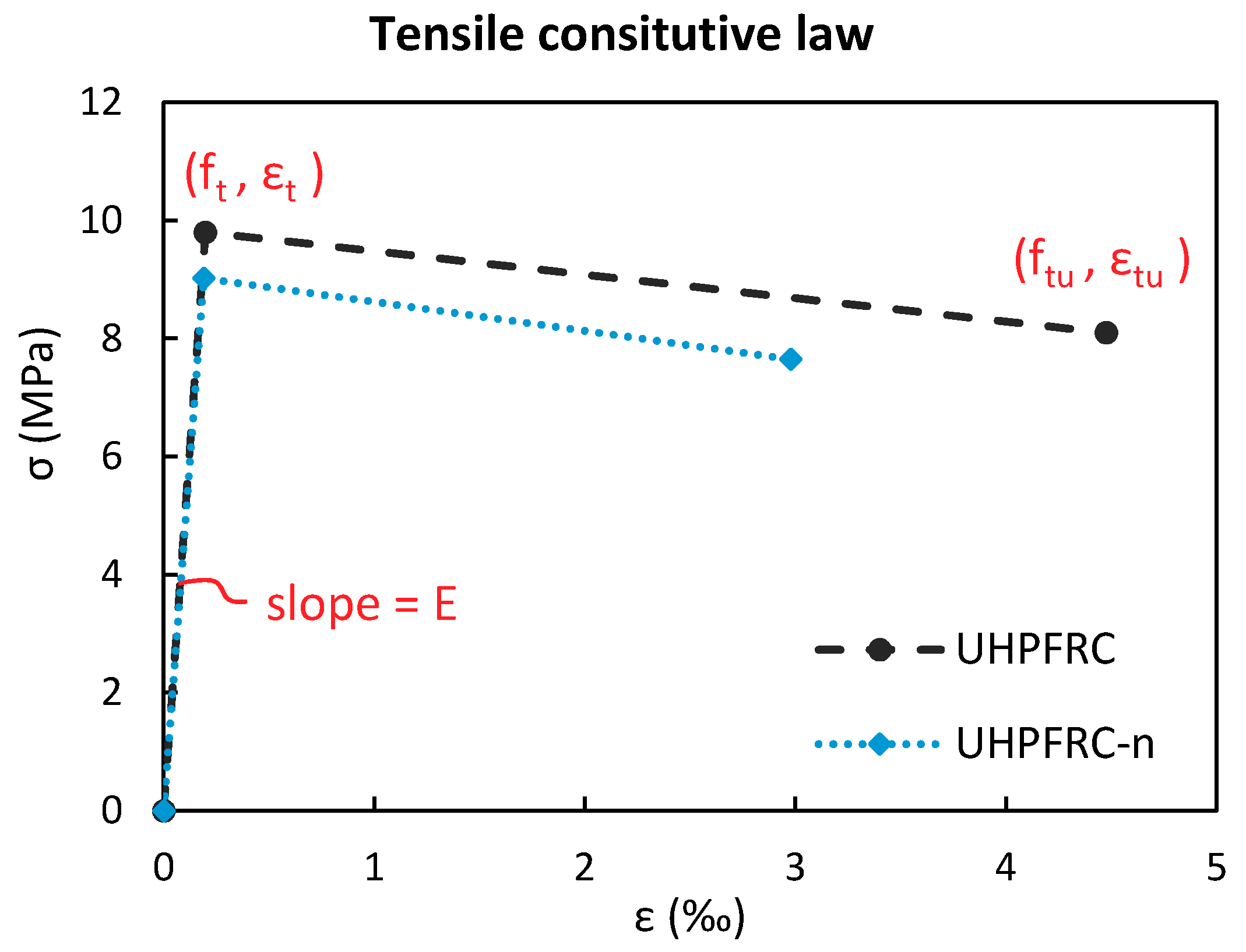
2.2.2. Flexural—Tensile Strength of UHFPRCs

Four-point bending tests were performed on prisms of size 100 × 100 × 500 mm3, with the loading points at beam length thirds, and the deflection at mid-span being measured by two displacement transducers on the front and back sides. The tensile response was obtained from the load vs deflection curves while using the simplified inverse analysis method that was proposed in [21,22]. This tensile constitutive model is defined by the parameters: elastic modulus (E), cracking strength (ft), ultimate cracking strength (ftu), and its associated strain (εtu). After reaching the ultimate strength, the first macrocrack localization is assumed to occur, and the final softening behavior is defined by a lineal stress/crack opening relation until reaching the crack opening axis at (w0).
Table 2 shows the stress-strain constitutive response that was obtained on the two UHPFRCs. All of the tested concretes presented deflection-hardening in the four-point bending test. The tensile behavior, as obtained through the inverse analysis, showed a low strain-hardening behavior (type 2 UHPFRC according with AFGC). The UHPFRC-n mix obtained a slightly lower mechanical response when compared to the UHPFRC mix (see representation in Figure 1). A type 3 UHPFRC according with AFGC (the most demanding UHPFRC type) requires a tensile strain hardening response. In this work, it was decided to use the developed type 2 UHPFRC due to previous knowledge with this mix and its good enough structural response at a competitive cost for real applications [23]. Table 2 also displays the coefficient of variation (CV) of the different parameters, being calculated as the ratio of the standard deviation to the average value of the data.

2.2.3. Air Permeability, Absorption, and Porosity Accessible to Water

Gas permeability tests, absorption tests, and porosity accessible to water tests were performed to completely characterize the four concrete types.
Concrete disks of diameter 150 mm and 50 mm height were used for the gas permeability tests, which were performed following the standard UNE 83981. The lateral surface of the disks was covered using a sealing paint (waterproof paint Sikalastic 612). For each concrete type, three samples were tested and Table 3 shows the average results and coefficient of variation obtained.
Regarding the absorption and porosity accessible to water, concrete disks of diameter 100 mm and 50 mm height were used following the standard UNE 83980. Six samples were tested for each concrete type. Table 3 displays the average results and coefficient of variation obtained.
It is clear that increasing the quality of concrete from SQC to HPC produces a significant decrease in the permeability of the matrix, absorption, and porosity to water while analyzing the three parameters. This decrease is more pronounced when moving to UHPFRC. The incorporation of the alumina nanofibers and crystalline admixtures in the UHPFRC-n mix in the percentages used in this work did not significantly change the values that were obtained for these parameters, showing slightly worse air permeability, but slightly better porosity and water absorption. The benefits of nanofibers and the crystalline admixture seem to have compensated for the slight increase in w/b ratio. The obtained results are consistent with those that were exposed in previous research by other authors [24], for SQC, HPC (similar to UHPC in [24]), and UHPFRC, demonstrating the improved durability of UHPFRC.

2.3. Methodology and Experimental Program in Cracked State

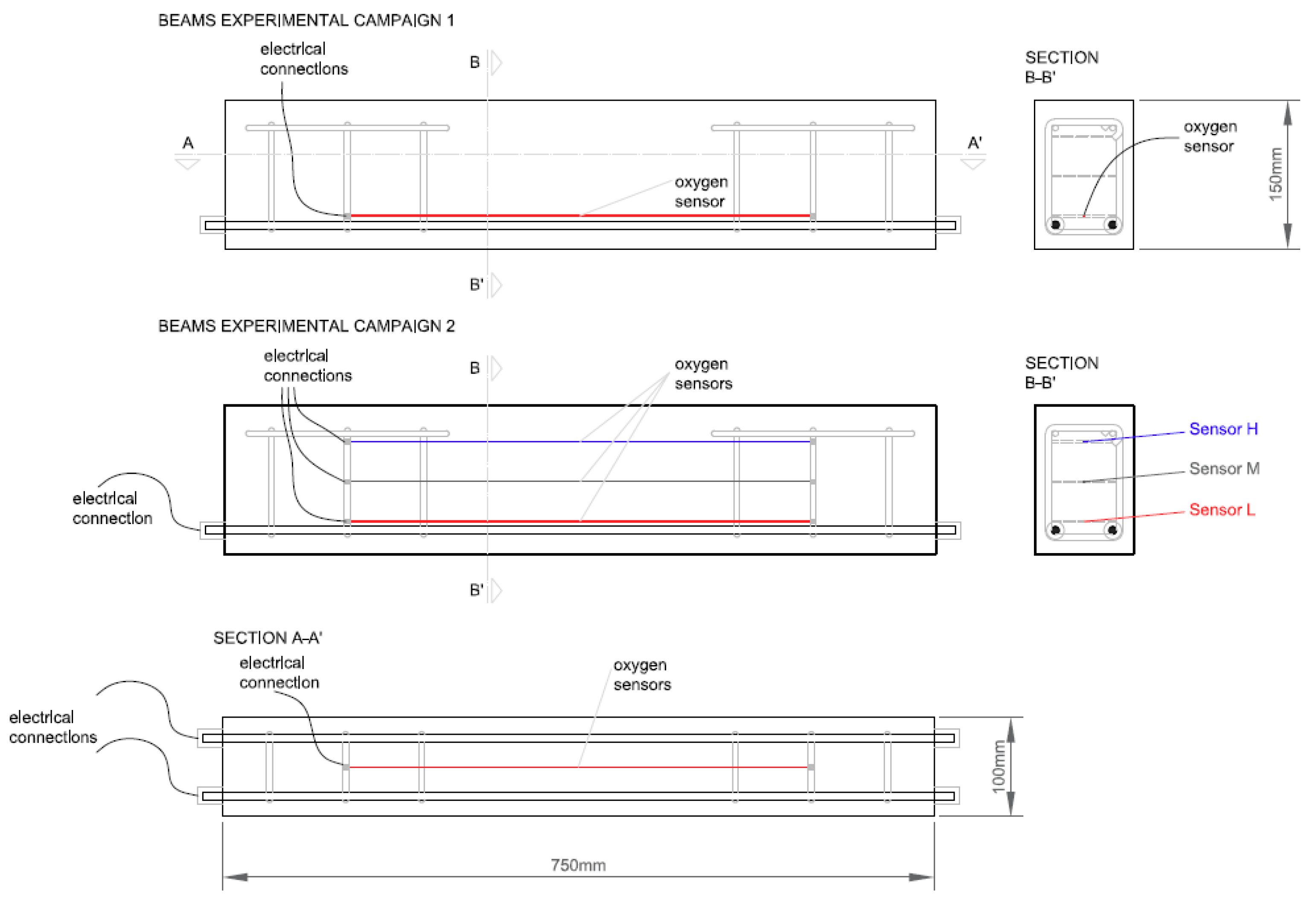
2.3.1. Concept and Experimental Program

It is clear that the UHPFRCs matrices display superior mechanical and durability properties if compared with those of traditional concrete types from the characterization results. This work aims to study whether these superior durability properties are also extended to the cracked state. To this purpose, small reinforced beams (Figure 2) were cast and pre-cracked (see Section 2.3.3) at three levels of severity, and its oxygen availability was analyzed in two experimental campaigns that are summarized in Table 4.
The first campaign was defined to compare the concretes evaluating the difference in oxygen availability while using one stainless steel sensor that was located in a fixed position at the lower part of the beam, as displayed in Figure 2. The four concrete types were all studied in uncracked state (Ref). HPC and UHPFRCs were studied in both low and high strain levels (HS). The comparison of the results that were obtained in these levels will allow for discerning the potential durability of cracked UHPFRCs as compared to traditional concrete types (SQC or HPC) in uncracked or low strain levels. Three beams were evaluated for each concrete and Table 4 shows the cracking level.
The second campaign was a detailed study that was performed on three beams that suffered high damage levels to evaluate the sensitivity of the result that was obtained when changing the position of the reference electrode. It aimed to determine whether the sensors are able to differentiate the cracking or damage levels in different areas of a same beam. In this case, each beam contained three sensors located at three heights (sensor H, M and L) and four sectors were studied, named S4, S3, S2, and S1, as displayed in Figure 3. The bottom surface will be tensioned while the upper surface will be compressed, since the pre-cracking method is a four-points bending test. The cracks are expected to be mainly produced in the middle span (sectors S2 and S3), and will be V-shaped, with the maximum crack opening in the tensioned surface (location of sensor L) and decreasing towards the compressed area (sensor H).

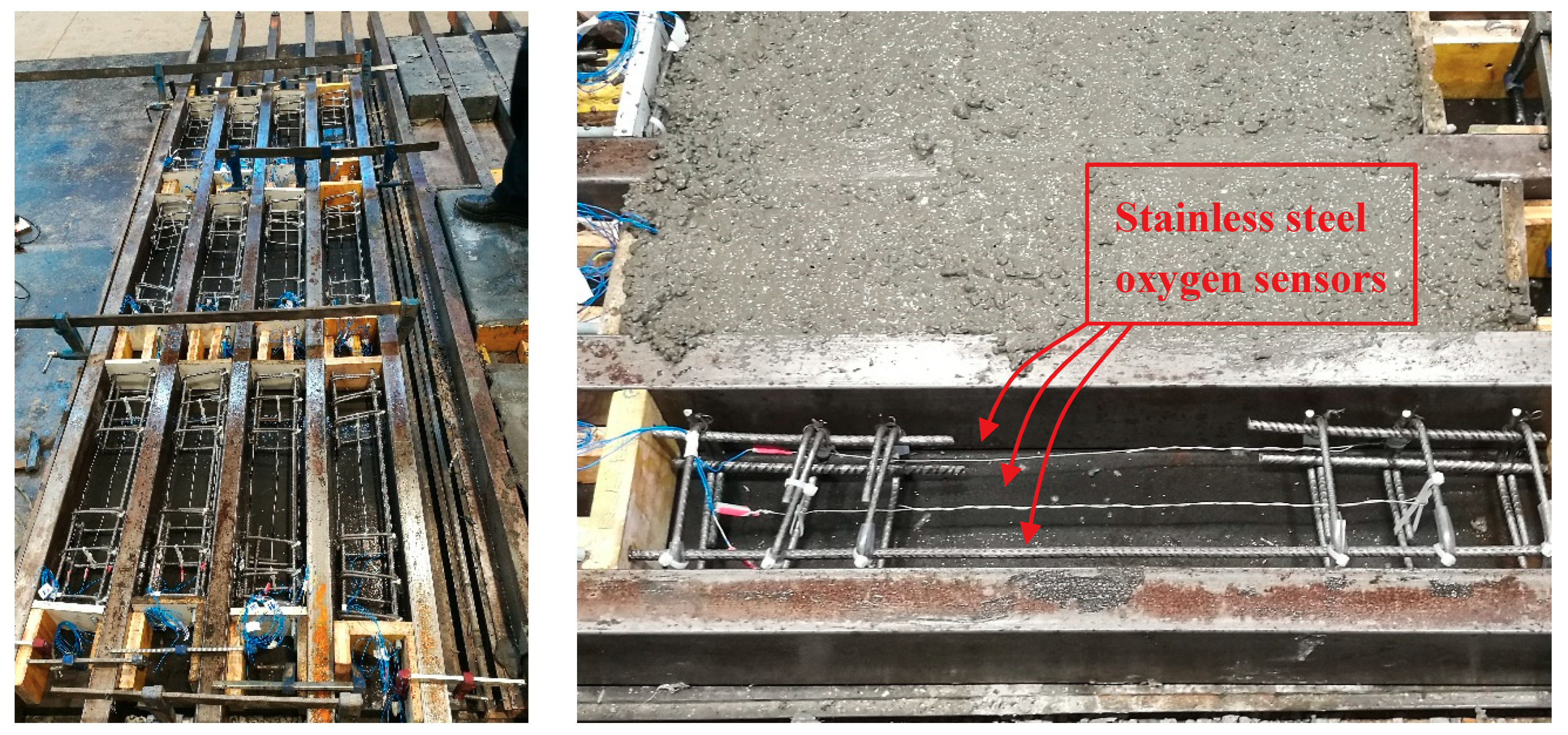
2.3.2. Preparation of the Beams and Casting

For each concrete type, the reinforced concrete beams of size 100 × 150 × 750 mm3 were casted. The reinforcement introduced in the beams consisted of 2ø8 lower reinforcing bars and 6ø6 stirrups to avoid shear failure during the pre-cracking stage. The concrete cover used is 20 mm.
Voltammetric sensors were embedded to evaluate the influence of the cracking pattern on oxygen penetration. These sensors were built from 0.8 mm stainless steel wire with an effective length of 500 mm, as depicted in Figure 4. Their electrical connection was performed while using copper single wire cables.

2.3.3. Pre-Cracking Procedure

A nonstandard test methodology was developed to generate a controlled crack state in a reinforced beam, based on a methodology that was previously proposed in [25]. After 28 days, the beams were pre-cracked while using a four-point bending test to produce cracks in the middle span (Figure 5left). Before starting the test, two rows of small disks were glued to one side of each sample to measure the strain variation with a Demountable Mechanical Strain Gauge (DEMEC) before, during, and after loading (Figure 5).The procedure for controlling crack width was to calculate the strain at six intervals separated by a distance of 100 mm and, from these values, to calculate the average strain (ε). The intervals between points 1–5 will be used to calculate the strain value at the depth of the stainless steel sensor L (εL) and points 6–10 will be used to calculate the same parameter at the depth of sensor M (εM). An LVDT was also placed in the middle span to measure the vertical displacement during the test.
The beams were pre-cracked at two damage levels, named low strain (LS) and high strain (HS) levels. Some beams remained unloaded as the reference beams state (Ref). The two strain levels are defined as:
  • Low Strain level (LS): average strain εM,avg at middle height of the beam around 0.5‰ as measured in loaded conditions. This level represents a condition inside the service limit state, in which a crack has been produced and it has been closed afterwards. This level produced one or two localized cracks of widths below 0.1 mm in traditional concretes and a series of very closed micro-crack of 10–15 microns in UHPFRCs at the reinforcement level.
  • High Strain level (HS): average strain εL,avg at the reinforcement level between 1‰ and 2‰ as measured after unloading. The condition used in practice was when the averaged strain of the three intervals exceeded the value of 1.5‰, since strain was measured between three intervals. This level represents a condition beyond the service limit state, with yielded or almost yielded rebars. This level produced localized cracks between 0.2–0.3 mm in traditional concretes and multiple micro-cracks of 25–50 microns in UHPFRCs at the reinforcement level. This cracking level represents a highly demanding condition, which is common for concrete structures in aggressive environments.
Figure 6 shows a comparison of the average strain values that were obtained at the lower row (εL) and at the medium row (εM) for all of the beams tested. The points of all the concrete types are clearly aligned following a linear trend, where the strain obtained at the bottom row is 1.78 times the strain obtained at the middle row. One of the points obtained at the HS level suffered higher than targeted strains due to the difficulties in controlling the process around the yielding point of the rebar.

2.3.4. Voltammetry Analysis to Detect Cracks

Cyclic voltammetry was used through custom-made fit-for-the-purpose voltammetric sensors once the beams were pre-cracked [17]. These sensors were used to detect the presence and size of cracks through the availability variation of oxygen.
Briefly, these sensors work in the following way: the electric current response that is obtained during the application of cyclic voltammetry is processed in the potential range associated to the oxygen reduction. In this potential range, the electric current is directly associated to the concentration of O2 inside of the material [17]. The analysis of the electric response allows for the definition of a parameter, named Id.O2, which is directly proportional to the ratio between the change in the electric current (logarithmic form) and the change in potential (Id.O2 = Δlog|i|/ΔV). Therefore, this parameter is correlated with oxygen availability, as demonstrated in a previous work [17]. Currently, the authors are working on a theoretical model for quantifying the concentration of oxygen from the results that were obtained with stainless steel voltammetry sensors. The results that are presented in this work show an initial experimental study to verify the relation between the Id.O2 parameter and the transport parameters of concrete in the different cracking states.
The cyclic voltammetry was used through the Autolab PGSTAT10 equipment, working with three electrodes and while using a saturated calomel electrode (SCE) as the reference electrode. A stainless steel plate sized 100 × 750 mm2 was used as a counter electrode (CE). The CE was l externally ocated, but electrical contact between the concrete beam and the plate was ensured through a wet cloth. The sweeping potential applied was in the range between 0.6 V and −1.1 V vs SCE.
Each measurement was repeated three times to have statistical certainty in each condition. During the test, the temperature and humidity conditions were kept controlled and constant (T = 25 °C ± 2 °C, RH ≈ 60%).
The reference position was the difference in the voltammetric test in each campaign. In the first experimental campaign, the reference electrode was always located in the middle span of the beam, at the height of sensor L. Conversely, in the second experimental campaign, the reference electrode was put in the same position and, additionally, in those spots that are indicated in Figure 3, to study the effect of changing the position of the sensor between the different sectors and heights. The relevance of this study is justified, because the closest area to the sensor is the one that will have more weight in the electrochemical reactions that will be produced on the surface of the sensor (oxygen reduction), closer to the position with the reference electrode.

3. Results and Discussion

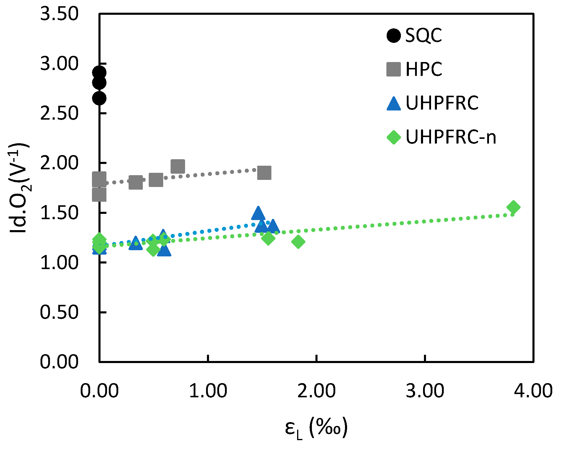
3.1. Experimental Campaign 1: Effect of Concrete Type on Cracking through Oxygen Availability

In this campaign, the absolute average value of the parameter Id.O2 is compared to the different strain levels (and thus crack sizes) for the four concrete mixes tested. The differences in the Id.O2 parameter obtained for HPC and UHPFRCs solely depend on the cracking pattern, which is multi-cracking in the case of the UHPFRCs and single-crack pattern with only ~2 cracks in HPC, since the strain levels and total crack width obtained were similar for each strain level.
Figure 7 compares the average values of the Id.O2 parameter obtained for each concrete type at the three strain levels (Ref, LS, and HS), as well as the standard deviation. These results show that the Id.O2 parameter was able to discern between the different levels in oxygen availability of the four concrete types, as well as detect the increase in oxygen presence when cracks or microcracks were produced in the concrete beams.
Analyzing the Id.O2 results that were obtained (Figure 7), SQC in uncracked state has the highest availability of oxygen, followed by HPC, and UHPFRCs obtain the lowest availability. Regarding the damage level (strain level) in HPC, it is clear that increasing the strain from Reference level to LS or HS increases the presence of oxygen (5% for LS and 20% for HS), which is a clear indicator of the presence of cracks in the beam.
In UHPFRCs, either this parameter is not sensitive to the LS level or the cracks are not able to transport oxygen. Thus, the LS condition in UHPFRCs was very similar to an uncracked situation in terms of oxygen availability inside the matrix. However, at the HS level, the Id.O2 parameter experienced increments of 11.5 % for UHPFRC-n and 18.8% for UHPFRC as compared with the value that was obtained for uncracked beams (Ref).
Despite the increase in oxygen availability that UHPFRC beams suffered in the HS condition when compared with uncracked UHPFRC beams, they obtained smaller Id.O2 values than the uncracked HPC, and clearly much smaller than uncracked SQC. These results indicate that cracked UHPFRC might have higher durability than the uncracked HPC. This higher durability would be even higher if the crack levels were maintained similar to LS.
It should be highlighted that the variation between beams of a same concrete and pre-cracking level was small, as seen in the standard deviation values, which show the similarity of the pre-cracking levels that were obtained in a specific concrete and the robustness of this parameter to evaluate oxygen availability. The coefficient of variation of the results that were obtained for each pre-cracking condition and the measurement repetitions performed were below 11% in all cases, which is a very good value when considering the heterogeneities of concrete.
Figure 8 shows the relation between the individual strain level reached in each beam after unloading and the O2 presence that was obtained in that beam through the stainless steel sensor. These results show a linear increase in the presence of oxygen when increasing the strain level for HPC, UHPFRC, and UHPFRC-n, with a very similar slope for the three concrete types. This result confirms the suitability of the stainless steel sensor that was used to evaluate the presence of oxygen in different concrete types, either from a FRC family or from a traditionally reinforced concrete. Additionally, when comparing UHPFRC-n and UHPFRC, it seems that the nano-alumina and crystalline admixtures provided a slight improvement under the HS conditions (seen as a lower oxygen presence for the HS strain levels), despite the extra amount of water that was used in this mix. However, this result would need further studies to be confirmed.
The percentual improvement calculated as per (1) has been summarized in Table 5 in order to evaluate the improvements of using HPC, UHPFRC, and UHPFRC-n compared to SQC. The results show that UHPFRCs in cracked states (LS and HS) have an improvement in the Id.O2 parameter of 50% when compared to uncracked SQC (that is, oxygen availability was reduced). There was also an improvement by using HPC, even in cracked state, as compared to SQC in the uncracked conditions, with a 23% of improvement. Similarly, when comparing UHPFRC and UHPFRC-n with HPC in uncracked state as per (2), the results indicate that UHPFRCs produce an improvement in in the Id.O2 parameter of 21% for UHPFRC and 25% in UHPFRC-n (Table 5).
Δ % v s S Q C _ R e f = I d . O 2 S Q C _ R e f I d . O 2 i _ j I d . O 2 S Q C _ R e f
Δ % v s H P C _ R e f = I d . O 2 H P C _ R e f I d . O 2 i _ j I d . O 2 H P C _ R e f
where i is the concrete type and j the cracking condition.

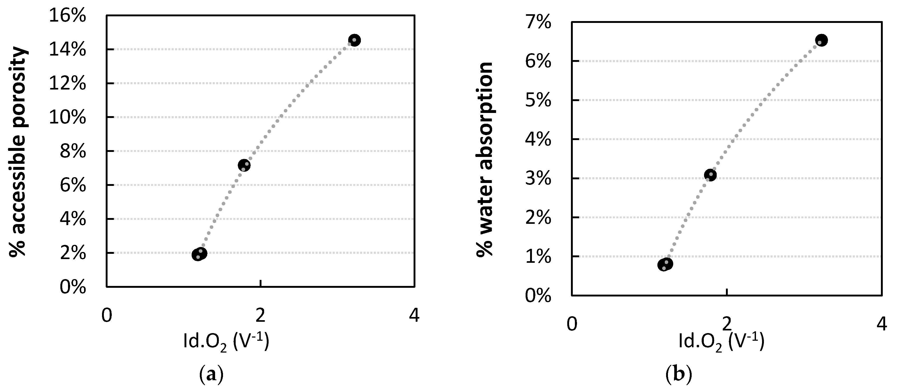
3.2. Discussion: Oxygen Availability Relation with Porosity and Permeability

From the experimental campaign 1, the value of the Id.O2 parameter inside the uncracked beams has been compared to the results of porosity accessible to water, water absorption, and air permeability. The concrete types with higher permeability are those with a higher amount of pores and higher values in the Id.O2 parameter, since the transport of gaseous agents is easier in porous concretes. Figure 9a,b represent the values of porosity accessible to water and absorption with the Id.O2 parameter.
Because of the relevance of the air permeability coefficient, which is a common parameter with standard procedures for its evaluation in concrete, its correlation with the Id.O2 parameter has been studied in depth in this section. Two additional concrete types that were analyzed in [17] have been added to this study to increase the robustness of this analysis. Figure 10 displays the resulting curve. The exponential curve adjusted to these points shows very good fitting (R2 = 0.98).
The equation that was obtained through this correlation allows for estimating the air permeability (K) parameters for the four concretes of this study in the three conditions studied (Ref, LS and HS). Using this equation, an estimation of the effective air permeability has been calculated in the different situations analyzed. Figure 11 represents the values of K that were calculated through the equation that was obtained from the correlation in Figure 10 while using the Id.O2 average values that were obtained (Figure 7). These values are consistent with those that were provided in [24,26], where they indicate that an UHPFRC will always have in standard conditions K < 10 × 10−19 m2.
Figure 12a shows the improvement produced in the estimated K parameter in UHPFRC, UHPFRC-n and HPC as compared to SQC in uncracked state (3). The permeability of UHPFRC and UHPFRC-n in uncracked state improves by 99% that of an SQC concrete. For the cracked beams (either at LS or HS levels), the value that was obtained for the estimated K parameter still produced an improvement when compared to uncracked SQC of a similar magnitude. When comparing the percentual increase to uncracked HPC (4), as shown in Figure 12b, the results indicate that UHPFRCs produce improvements of 80% in Ref and LS conditions and around 65–75% in HS conditions.
Δ % v s S Q C _ R e f = K S Q C _ R e f K i _ j K S Q C _ R e f
Δ % v s H P C _ R e f = K H P C _ R e f K i _ j K H P C _ R e f
where i is the concrete type and j the cracking condition.
It is clear that UHPFRC concrete types produced a clear durability improvement in the cracked state compared to HPC, due to their significantly lower air permeability, after the results that were obtained in Figure 11 and Figure 12. The reduction of the air permeability and, therefore, oxygen entrance, of UHPFRC concrete types, even after suffering several aggressive levels of stress, will certainly improve the protection of the reinforcement against corrosion. Subsequently, the amount of oxygen that will be able to reach the reinforcement surface will be smaller and the kinetics of the REDOX reaction will be reduced, since this gas is the main oxidizing agent of the rebar corrosion reaction.
This demonstrates that a situation with high number of cracks of small width is more beneficial in terms of durability than a situation with a single crack of higher crack width, even if their global stress level and total crack width are comparable. In other words, having 10 cracks of 0.01 mm is better in terms of durability than having one crack of 0.10 mm. These results support that using these concretes in construction with a design fitted for their specific behavior will produce high durability structures with an extended service life, even after suffering conditions producing cracks.

3.3. Experimental Campaign 2: Sensitivity of the Sensor at Different Locations

In the second campaign, the sensors were tested to differentiate the cracking levels in different areas of a same beam, as depicted in Figure 3. The average values are obtained for the three repetitions for each point. Figure 13 displays these values and their standard deviation.
The results that were obtained in the HPC beam in uncracked state (Figure 13a, bars labelled as Ref) show very similar Id.O2 values in the three sensor zones (L, M, H). For the beam pre-cracked at the HS level, higher oxygen availability was detected at the three sensor zones, even in sectors S1 and S4, where minimum cracking was thought to have occurred (probably because of the existence of shear cracks). Sector 2 shows the most relevant increase in oxygen presence in the sensor that was located at the low area (L), indicating the location of a crack produced by bending, while the rest of measures do not show a clear trend.
The four sectors displayed a similar behavior regarding the results of UHPFRC concretes in cracked state (Figure 13b,c), with the highest oxygen presence in zone L, where the cracks were wider. On the contrary, the lower value was consistently obtained in zone H, and there was a clear trend of decreasing oxygen content going towards the upper part of the beam in all cases. This demonstrates the good sensitivity of this sensor, which was able to detect different oxygen availability levels at the three studied heights, despite UHPFRCs’ extremely thin cracks.
Additionally, the UHPFRC-n mix shows slightly lower values of oxygen availability inside the matrix when compared to UHPFRC, which is especially noted at the zone H. This is a possible indicator of the durability improvement produced by the functionalizing agents added to this mix.
When comparing the results of HPC and UHPFRCs, it can be concluded that the crack patterns in UHPFRCs appeared to be more distributed and uniform in the different sectors and studied heights, while, in HPC, the relative position of the crack compared to the position of the sensor was unclear. The HPC cracking pattern exhibits wider and longer cracks, which are generally visible to the naked eye, whereas, multiple thin cracks are produced in UHPFRC, which are only visible when using microscopes. These cracks can be even more reduced in the interior of the beam when compared to the surface crack, as reported previously in other works [10,11]. Subsequently, together with the high content of steel fibers in UHPFRC, and also with nano-fibers in UHPFRC-n concrete types, the oxygen availability can be reduced even further.

4. Conclusions

Several conclusions can be drawn from this study:
  • The stainless steel voltammetric sensor used in this work and the Id.O2 parameter were able to detect variations in the availability of oxygen and, thus, detect differences in size of cracks produced in reinforced concrete in the range of 0.1–0.3 mm, as well as smaller cracks in the range of microns. This sensor was also able to detect differences in crack pattern for a same concrete type, depending on the zone that is measured. The study of the sensitivity of the sensor at different locations in UHPFRCs shows that oxygen availability decreased while going towards the upper part of the beam, as the crack width was thinner.
  • In uncracked conditions, HPC and UHPFRCs improved the air permeability coefficient by three orders of magnitude, and the absorption and porosity to water by one order of magnitude. For cracked conditions, the air permeability coefficient for cracked concrete has been estimated through a correlation model. The obtained results show that cracked UHPFRCs improved 65–80% the values of uncracked HPC and 98–99% the values of uncracked SQC. This improvement is produced by the compacity of UHPFRCs matrices and their diffused micro-crack pattern.
  • Oxygen availability, as measured in UHPFRC and UHPFRC-n with the stainless steel sensor, indicates that cracked UHPFRCs registered improvements in the Id.O2 parameter in the range of 20–30% comparing to uncracked HPC and 50–60% when comparing to uncracked SQC.
  • Increasing the damage level or strain in HPC beams increased the presence of oxygen in 5% for LS and 20% for HS when compared to the uncracked level. In the case of UHPFRCs, the beams cracked to LS conditions showed the same oxygen availability than uncracked beams. However, the beams cracked at the HS level experienced increments between 11 and 19% for UHPFRC and UHPFRC-n.
  • This work demonstrates that multi-cracking patterns are more beneficial in terms of air transport than single crack patterns for a comparable strain level, especially for small strain levels, and that using these concretes in construction will potentially produce high durability structures with an extended service life, even after suffering cracks.
Future studies that can be derived from this work may focus on establishing mathematical models of cracking and oxygen presence in concrete with variable fibers content, as well as in evaluating the internal tortuosity and crack width variation in the interior of concrete by means of the availability of oxygen in different areas, or while analyzing the effects of this different oxygen availability in the corrosion processes produced.

Author Contributions

Conceptualization, P.S. and M.V.; methodology, P.S., A.M.-I.; formal analysis, A.M.-I. and M.R.-F.; investigation, A.M.-I., E.J.M.-A. and J.L.-F.; resources, P.S. and M.V.; writing—review and editing, M.R.-F. and A.M.-I.; supervision, P.S. and M.V.; project administration, M.R.-F.; funding acquisition, A.M.-I., M.V., P.S. and M.R.-F. All authors have read and agreed to the published version of the manuscript.

Funding

The authors would like to express their gratitude to the Spanish Ministry of Science and Innovation for the pre-doctoral scholarship granted to Ana Martínez Ibernón (FPU 16/00723), to the Universitat Politècnica de València for the pre-doctoral scholarship granted to Josep Ramon Lliso Ferrando (FPI-UPV-2018), and the European Union’s Horizon 2020 ReSHEALience project (Grant Agreement No. 760824).

Conflicts of Interest

The authors declare no conflict of interest.

References

  1. Du Beton, F.I. International Federation for Structural Concrete (fib). In Fib Model Code for Concrete Structures 2010; John Wiley & Sons: Hoboken, NJ, USA, 2013. [Google Scholar] [CrossRef]
  2. Yoo, D.-Y.; Banthia, N. Mechanical properties of ultra-high-performance fiber-reinforced concrete: A review. Cem. Concr. Compos. 2016, 73, 267–280. [Google Scholar] [CrossRef]
  3. Ahlborn, T.; Misson, D.; Peuse, E.; Gilbertson, C. Durability and strength characterization of ultra-high performance concrete under variable curing regimes. In Proceedings of the Second International Symposium on Ultra High Performance Concrete, Kassel, Germany, 5–7 March 2008; ISBN 978-3-89958-376-2. [Google Scholar]
  4. van Zijl, G.; Wittmann, F. Durability of Strain-Hardening Fibre-Reinforced Cement-Based Composites (SHCC). Rilem State Art Rep. 2011. [Google Scholar] [CrossRef]
  5. Li, V.C. On Engineered Cementitious Composites (ECC) A Review of the Material and Its Applications. J. Adv. Concr. Technol. 2003, 1, 215–230. Available online: http://hdl.handle.net/2027.42/84703 (accessed on 28 December 2019). [CrossRef] [Green Version]
  6. Asgari, M.A.; Mastali, M.; Dalvand, A.; Abdollahnejad, Z. Development of deflection hardening cementitious composites using glass fibres for flexural repairing/strengthening concrete beams: Experimental and numerical studies. Eur. J. Environ. Civ. Eng. 2019, 23, 916–944. [Google Scholar] [CrossRef]
  7. Derucher, K.N. ‘Failure mechanism of concrete’ in Composite Materials: Testing and Design (Fifth Conference). In ASTM STP 674; Tsai, S.W., Ed.; American Society for Testing and Materials: Philadelphia, PA, USA, 1982; pp. 664–679. [Google Scholar]
  8. Ravindrarajah, R.S.; Swamy, R.N. Load effects on fracture of concrete. Mater. Struct. 1989, 22, 15–22. [Google Scholar] [CrossRef]
  9. Bascoul, A. State of the art report—Part 2: Mechanical micro-cracking of concrete. Mater. Struct. 1996, 29, 67–78. [Google Scholar] [CrossRef]
  10. Damgaard-Jensen, A.; Chatterji, S. State of the art report on micro-cracking and lifetime of concrete—Part I. Mater. Struct. 1996, 29, 3–8. [Google Scholar] [CrossRef]
  11. Berrocal, C.G.; Löfgren, I.; Lundgren, K.; Görander, N.; Halldén, C. Characterisation of bending cracks in R/FRC using image analysis. Cem. Concr. Res. 2016, 90, 104–116. [Google Scholar] [CrossRef] [Green Version]
  12. Correia, M.J.; Pereira, E.; Salta, M.; Fonseca, I. Sensor for oxygen evaluation in concrete. Cem. Concr. Compos. 2006, 28, 226–232. [Google Scholar] [CrossRef]
  13. Yoon, I.-S. Comprehensive Approach to Calculate Oxygen Diffusivity of Cementitious Materials Considering Carbonation. Int. J. Concr. Struct. Mater. 2018, 12, 16. [Google Scholar] [CrossRef]
  14. Banthia, N.; Zanotti, C.; Sappakittipakorn, M. Sustainable fiber reinforced concrete for repair applications. Constr. Build. Mater. 2014, 67, 405–412. [Google Scholar] [CrossRef]
  15. Berrocal, L.I.; G, C.; Lundgren, K. The effect of fibres on steel bar corrosion and flexural behaviour of corroded RC beams. Eng. Struct. 2018, 163, 409–425. [Google Scholar] [CrossRef] [Green Version]
  16. Zamora, J.R. Sistema de Sensores Embebidos para Monitorizar la Corrosión en Estructuras de Hormigón Armado. Fundamentos, Metodología y Aplicaciones. Ph.D. Thesis, Universitat Politècnica de València, València, Spain, 2018. [Google Scholar]
  17. Martínez-Ibernón, A.; Gandía-Romero, J.; Lliso-Ferrando, J.; Soto, J. Determination of oxygen availability in concrete by means of voltammetric sensors. In Proceedings of the EUROCORR 2019, Sevilla, Spain, 8–13 September 2019. [Google Scholar]
  18. Sisomphon, K.; Copuroglu, O.; Koenders, E. Self-healing of surface cracks in mortars with expansive additive and crystalline additive. Cem. Concr. Compos. 2012, 34, 566–574. [Google Scholar] [CrossRef]
  19. Ferrara, L.; Krelani, V.; Carsana, M. A “fracture testing” based approach to assess crack healing of concrete with and without crystalline admixtures. Constr. Build. Mater. 2014, 68, 535–551. [Google Scholar] [CrossRef]
  20. Roig-Flores, M.; Pirritano, F.; Serna, P.; Ferrara, L. Effect of crystalline admixtures on the self-healing capability of early-age concrete studied by means of permeability and crack closing tests. Constr. Build. Mater. 2016, 114, 447–457. [Google Scholar] [CrossRef]
  21. López, J.Á.; Serna, P.; Navarro-Gregori, J.; Camacho, E. An inverse analysis method based on deflection to curvature transformation to determine the tensile properties of UHPFRC. Mater. Struct. 2015, 48, 3703–3718. [Google Scholar] [CrossRef]
  22. Martínez, J.L. Characterisation of the Tensile Behaviour of UHPC by Means of Four-Point Bending Tests. Ph.D. Thesis, Universitat Politècnica de València, València, Spain, 2017. [Google Scholar]
  23. Lopez, J.A.; Serna, P.; Camacho, E.; Coll, H.; Navarro-Gregori, J. First ultra-high-performance fibre-reinforced concrete footbridge in Spain: Design and construction. Struct. Eng. Int. 2014, 24, 101–104. [Google Scholar] [CrossRef]
  24. Resplendino, J.; Petitjean, J. French recommendations for ultra-high performance fiber-reinforced concretes. In Proceedings of the International RILEM Workshop on Test and Design Methods for Steel Fibre Reinforced Concrete, Bochum, Germany, 20–21 March 2003. [Google Scholar]
  25. Negrini, A.; Roig-Flores, M.; Mezquida-Alcaraz, E.; Ferrara, L.; Serna, P. Effect of crack pattern on the self-healing capability in traditional, HPC and UHPFRC concretes measured by water and chloride permeability. In Proceedings of the 7th International Conference on Concrete Repair, Cluj Napoca, Romania, 30 September–2 October 2019; Volume 289. [Google Scholar] [CrossRef]
  26. AFGC Groupe de travail BFUP. Bétons fibrés à ultra-hautes performances. In Recommandations—Ultra High Performance Fibre-Reinforced Concretes; AFGC Groupe de travail BFUP: Paris, France, 2013. [Google Scholar]
Figure 1. Bilinear σ–ε relationship for UHPFRC and UHPFRC-n mixes before crack localization.
Applsci 10 00239 g001
Figure 2. Beams scheme for the two experimental campaigns showing the position of the sensors.
Applsci 10 00239 g002
Figure 3. Diagram showing the three sensors levels and four sectors of the study.
Applsci 10 00239 g003
Figure 4. Molds and stainless steel sensors placed before and after pouring concrete.
Applsci 10 00239 g004
Figure 5. Four-point bending test setup (left) and Demountable Mechanical Strain Gauge (DEMEC) points location (right).
Applsci 10 00239 g005
Figure 6. Comparison of the strain obtained at the bottom row (εL) and middle height row (εM).
Applsci 10 00239 g006
Figure 7. Absolute average values Id.O2 parameter for each analyzed scenario.
Applsci 10 00239 g007
Figure 8. Influence of the strain level (damage level) on the presence of oxygen for the concretes studied.
Applsci 10 00239 g008
Figure 9. (a) Curve Id.O2 vs porosity accessible to water (UNE 83980) (b) Curve Id.O2 vs water absorption (UNE 83980).
Applsci 10 00239 g009
Figure 10. Correlation between the parameters Id.O2 and K air permeability coefficient (UNE 83981).
Applsci 10 00239 g010
Figure 11. K coefficients that were estimated through the correlation from Figure 10.
Applsci 10 00239 g011
Figure 12. Percentual increase of estimated K (a) when compared to SQC_Ref. (b) as compared to HPC_Ref.
Applsci 10 00239 g012
Figure 13. Sectorization Id.O2 results obtained at the HS level in the (a) High Performance Concrete HPC) beam, (b) UHPFRC beams, (c) UHPFRC-n beam.
Applsci 10 00239 g013aApplsci 10 00239 g013b
Table 1. Composition of the four concrete types studied and results of control tests.
Kg/m3SQCHPCUHPFRCUHPFRC-n
Cement I 42.5 R-SR5350450800800
Silica Fume 50175175
Water192160160165.0
w/c0.5910.3560.2000.206
w/b0.5910.3200.1640.169
Aggregate 7/12600200
Aggregate 4/7300600
Natural sand950950
Limestone filler60
Siliceous sand–medium 0/1.6 mm 565565
Siliceous sand–fine 0/0.5 mm 302302
Siliceous sand–flour (<50 μm) 225225
Short steel fibers 13/0.2 160160
Superplasticizer A0.7
Superplasticizer B 5.53030
Crystalline admixture 7.8
Alumina nanofibers 2.438
Slump or [slump flow] (mm)180190700620
Compressive strength at 28d (MPa)40.279.8144.7133.6
Table 2. Parameters of the constitutive tensile law obtained for Ultra-High-Performance Fiber-Reinforced Concrete (UHPFRC) and UHPFRC-n.
Concrete TypeSpec.Constitutive Tensile Law
ft (MPa)ftu (MPa)εtu (‰)E (MPa)ωo (mm)
UHPFRCavg.9.808.104.4849,6392.87
CV6.74%17.72%24.86%4.77%16.46%
UHPFRC-navg.9.027.652.9847,5172.49
CV11.28%11.79%52.63%1.72%14.69%
Table 3. Average values obtained in air permeability tests (UNE 83981), porosity accessible to water and absorption tests (UNE 83980).
Air Permeability coef. (10−19 m2)CV% Porosity Accessible to WaterCV% Water AbsorptionCV
SQC103011.07%14.53%3.00%6.53%3.53%
HPC6.2329.96%7.15%3.20%3.08%3.25%
UHPFRC1.3826.48%1.96%3.56%0.81%3.63%
UHPRFC-n1.9430.10%1.87%13.18%0.78%13.11%
Table 4. Summary of the distribution of beams for the experimental campaigns performed and number of specimens per case (No.).
Experimental Campaign 1Experimental Campaign 2
Single Crack PatternMultiple Cracks Pattern
ConcreteCrack LevelNo.ConcreteCrack LevelNo.ConcreteCrack LevelNo.
SQCUncracked3UHPFRCUncracked3HPCHigh Strain1
HPCUncracked3Low Strain3UHPFRCHigh Strain1
Low Strain3High Strain3UHPFRC-nHigh Strain1
High Strain1
UHPFRC-nUncracked3
Low Strain3
High Strain3
Table 5. Percentual improvement of Id.O2 as compared to uncracked SQC_Ref and HPC_Ref.
Δ% vs. SQC_RefΔ% vs. HPC_Ref
HPCUHPFRCUHPFRC-nUHPFRCUHPFRC-n
Ref36.05%57.32%57.03%33.26%32.81%
LS33.10%56.97%57.16%32.71%33.01%
HS23.24%49.30%52.09%20.72%25.07%

