Article

A Gesture-Based Teleoperation System for Compliant Robot Motion

1
Department of Mechanical Engineering and Automation, Northeastern University, Shenyang 110819, Liaoning Province, China
2
SoftLab, Bristol Robotics Laboratory, University of Bristol, Bristol BS16 1QY, UK
*
Author to whom correspondence should be addressed.
Appl. Sci. 2019, 9(24), 5290; https://doi.org/10.3390/app9245290
Submission received: 11 October 2019 / Revised: 23 November 2019 / Accepted: 29 November 2019 / Published: 4 December 2019

Abstract

:
Currently, the gesture-based teleoperation system cannot generate precise and compliant robot motions because human motions have the characteristics of uncertainty and low-resolution. In this paper, a novel, gesture-based teleoperation system for compliant robot motion is proposed. By using the left hand as the commander and the right hand as a positioner, different operation modes and scaling ratios can be tuned on-the-fly to meet the accuracy and efficiency requirements. Moreover, a vibration-based force feedback system was developed to provide the operator with a telepresence capability. The pick-and-place and peg-in-hole tasks were used to test the effectiveness of the teleoperation system we developed. The experiment results prove that the gesture-based teleoperation system is effective at handling compliant robot motions.

1. Introduction

With the development of space, ocean and atomic technology, there is an urgent need for robots to work in dangerous, uncertain environments and inaccessible workplaces [1]. Therefore, the teleoperation system of robots has received more and more attention. In industrial environments, many robotic tasks (e.g., assembly, grinding, painting, welding, etc.) require precise position and compliance control. Therefore, they asks the teleoperation systems not only to achieve precise positional control but also to have the function of force feedback.
Teleoperation means the operator can remotely control the robot [2,3,4]. Usually, a physical human–robot interaction (pHRI) device is used to provide the motion commands [5], and such devices can be divided into joystick devices and motion-tracking devices. The joystick is usually a better control device because it can reflect forces that are experienced at the remote site [6]. For example, with Phantom [7] or Omega 7 [8], the contact force can be fed back to the operator. However, usually, the movement range is limited, and the mapping has to be tuned for different robots.
The other way to teleoperate a robot is through a motion-tracking device. An operator can use his/her body to command the robot to move. There is no physical contact or constraints. Hand gestures are an effective way to teleoperate a robot. The hands’ movements can be used to guide the robot to move directly. The static or dynamic gestures can also be mapped to different primitive robot actions. Gestures can be detected using different sensors, such as monocular cameras [9], stereo cameras [10], RGB-D sensors (i.e., Kinect, Xtion, RealSense) [11,12] and sEMG sensors [13]. However, because of the limited sensing capability and accuracy, these devices can only be used to identify predefined gestures or track hands with low resolution. These facts limit the application of gesture-based human robot interaction. The leap motion (LM) sensor is a promising alternative to the above-mentioned sensors. It can track fingers, hands and even joints with an accuracy of up to 200 μ m [14]. Not only the position but also the rotation can be fed back in real-time at 60 fps [15]. It has been used to teleoperate different robots. Bassily developed a human-robot interaction system based on an LM sensor to operate a robot manipulator intuitively and adaptively [16]. Hernoux used the LM sensor to track 3D hand motion and transfer the motion to an industrial robot [17]. Jin developed a gesture-based non-contact teleoperation system to operate tabletop objects; both gestures and palm positions are used [18]. He also investigated the multiple LM configurations to improve the robustness of the hand tracking function [19]. Despinoy used the joint angles and palm position to assist robotic surgical training [20].
The LM sensor and gesture-based human-robot interface have been successfully used in these applications. However, the gesture-based teleoperation technique has its own limitations. Firstly, since the motion of human arm/hand/limb motion is unstable and imprecise, it cannot be used to finish tight tolerant assembly skills. In some research, interval Kalman filter is used to filter the human motion [21]. However, the low-frequency movement still may affect the final robot motion. Secondly, although the LM is up to sub-millimeter accuracy, it still cannot meet the requirements of a tight tolerant assembly task where the error is in micrometer range. Thirdly, the LM has a limited sensing range, and it cannot be applied to tasks with large workspace; finally, like other non-contact interaction methods, the lack of force feedback makes it difficult to be applied in compliant tasks, which are common in complex assembly processes [22,23].
Force feedback is an important module in a teleoperation system. The force feedback can be realized by haptic devices or vibrotactile devices. Because of the complexity, low reliability, and high cost of haptic devices, the applications of haptic feedback systems are limited [24]. For vibrotactile feedback, Eitan Raveha added vibrotactile feedback to a myoelectric-controlled hand. When visual feedback was disturbed, it improved performance during a functional test [25]. Khasnobish conveyed shape information with vibrotactile feedback to aid in the recognition of items when tactile perception was hindered [26]. Hussain carried out a pick-and-place experiment with ten subjects. Vibrotactile feedback significantly improved the performance in task execution in terms of completion time, exerted force and perceived effectiveness [27]. Therefore, the vibrotactile device is an attractive option for implementing force feedback in teleoperation systems.
Therefore, this paper proposes a novel gesture-based teleoperation system, which can generate precise robot motions as well as compliant robot motions. First, the effects of the low-frequency movement of human hands are mitigated by a scalable human-robot motion mapping mechanism. Second, a new interaction logic, scalable human-robot motion mapping mechanism and single-axis mode are used to improve the teleoperation’s accuracy. Third, to expand the sensing range of the leap motion, the clutch mode is introduced. Then, to meet requirements of complaint assembly skill, a vibration-based force feedback system was developed to let the operator feel the contact force. Lastly, an active force control mechanism was also designed to restrict the contact force within a safe range.
Compared to the other gesture-based teleoperation method, the proposed one combines both hand gestures and hand movements, which results in more flexible robotic motions. The force feedback capabilities and multiple operation modes make it possible to perform compliant and precise robot motion.
The remainder of the paper is organized as follows: Section 2 introduces the system’s human-machine interface, including the leap motion-based gesture recognition, hand-robot-tool mapping and force feedback loop. Section 3 describes refining the above interfaces to meet the requirements of actual tasks and integrating them into the system. The pick-and-place and peg-in-hole tasks were used to test the effectiveness of the developed teleoperation system, as described in Section 4. Section 5 gives some conclusions and outlines future work.

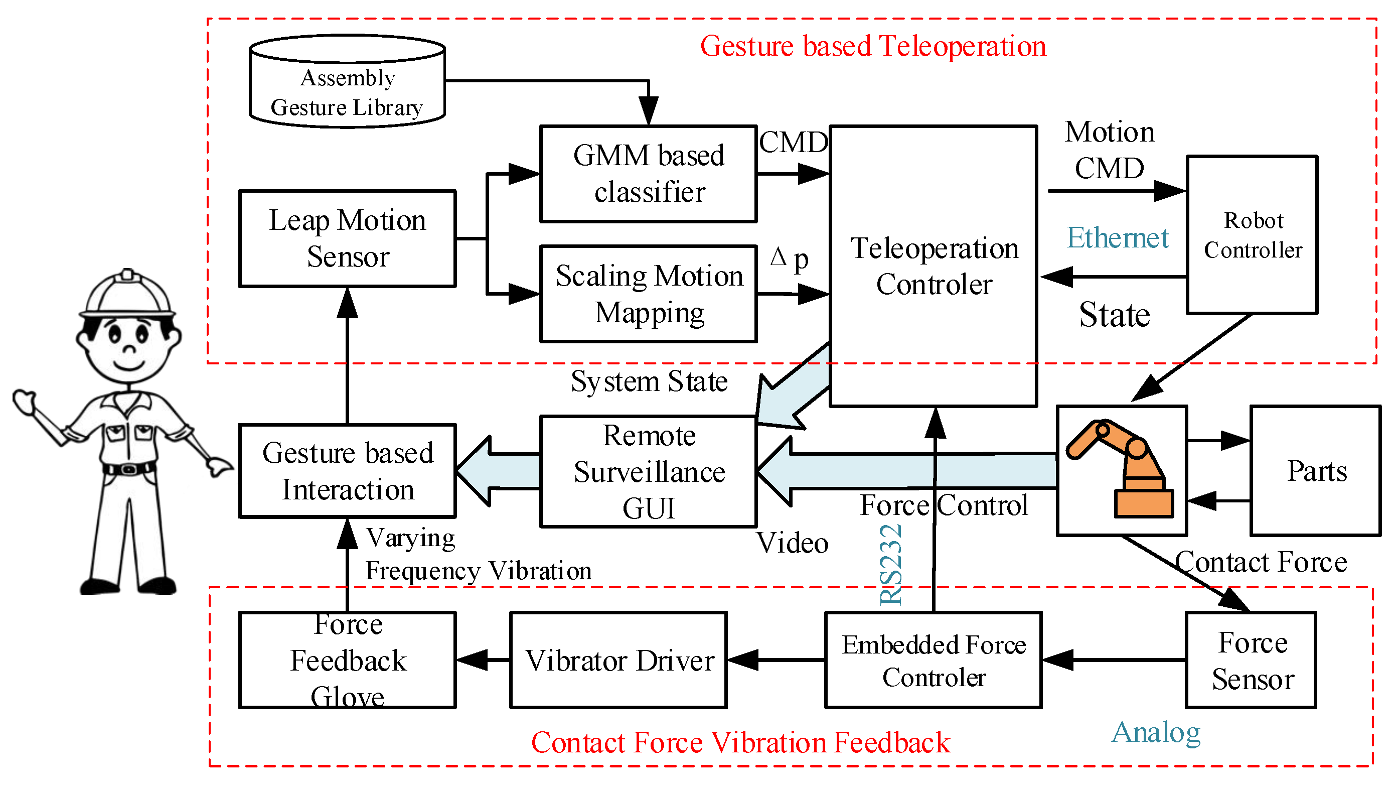
2. Gesture-Based Human-Robot Interface

2.1. Leap Motion Based Gesture Recognition

Leap motion is a hand tracking device based on the structured light technique. It can recognize and track dual hands at sub-millimeter accuracy and 60 fps. With the leap motion API, position and orientation of the palm, the position of the fingertip and joints can be provided in real-time. The hand gesture recognition is realized in three processes: feature selection, offline training and online classification.

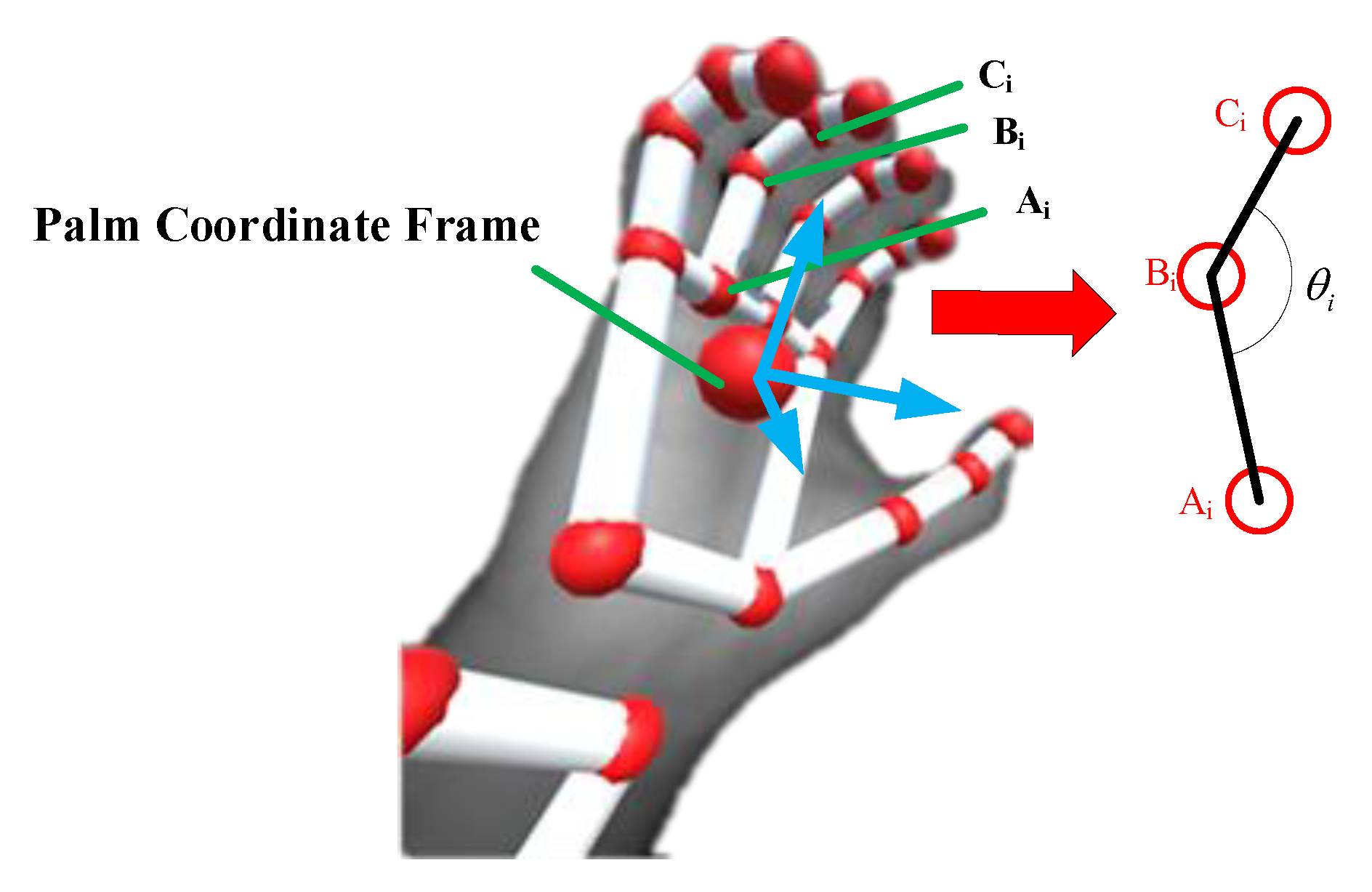
2.1.1. Feature Selection

In order to reduce the influence of the variance of hand sizes and shapes among different people, in this paper the angular features are used. As shown in Figure 1, the bone/joint position A i = ( x A i , y A i , z A i ) , B i = ( x B i , y B i , z B i ) , C i = ( x C i , y C i , z C i ) , i = 1 , , 5 can be provided by the leap motion sensor.
According to laws of cosine, the bending angle θ i is
θ i = arccos A i B i 2 + B i C i 2 A i C i 2 A i B i 2 + B i C i 2 A i C i 2 2 A i B i B i C i 2 A i B i B i C i .
After conversion, five features θ 1 θ 2 θ 3 θ 4 θ 5 T are obtained. These features describe the bending angle of each finger, which are enough to distinguish the simple gestures. For more complex gestures, it is better to incorporate more features such as other joint angles and angles between fingers. In this paper, for simplicity, only the bending angles are used.

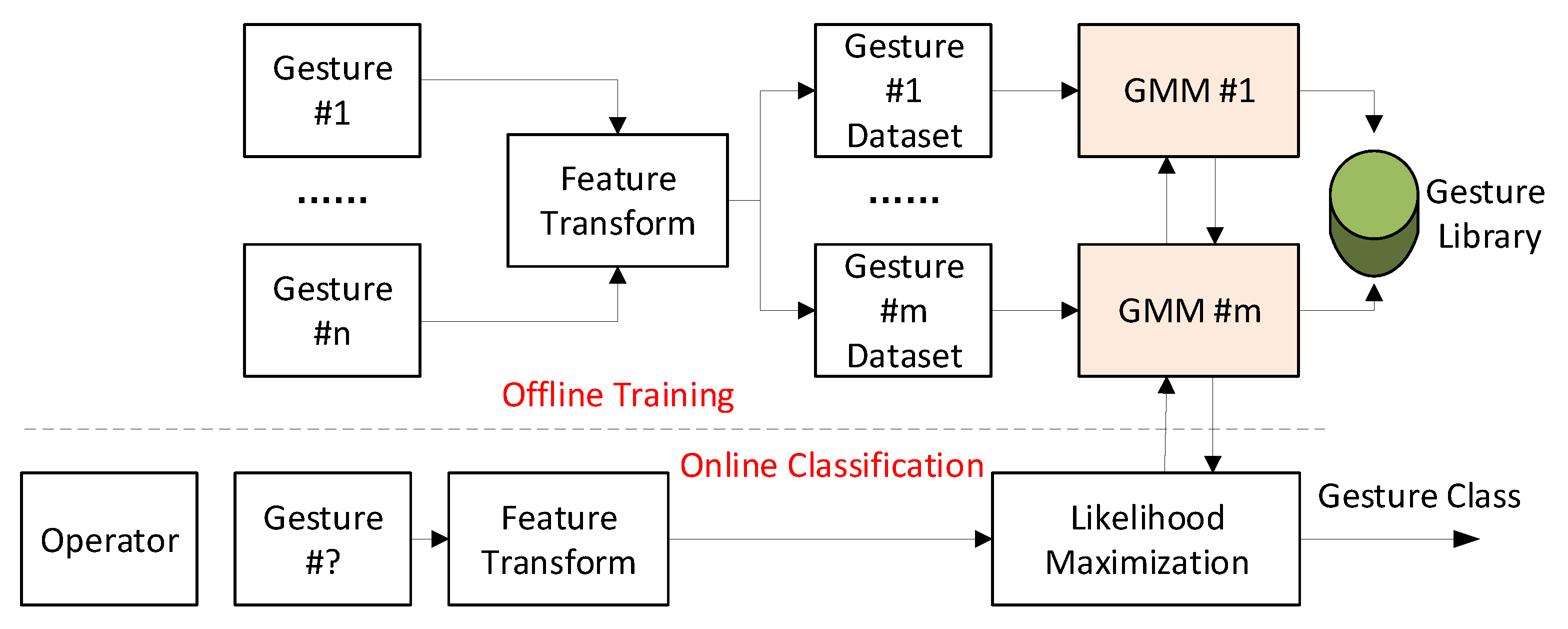
2.1.2. Gaussian Mixture Model (GMM) Based Classification

Gesture recognition is a supervised learning problem; i.e., training a classifier using a labeled dataset and then finding the right label for a test sample. As is shown in Figure 2, gesture samples are taken for offline training to build a gesture library, and then the operator’s gesture can be classified online. It is assumed that there are M hand gestures, and for each gesture, there are N samples. The commonly-used recognition algorithms for gestures are support vector machines (SVMs), artificial neural networks (ANNs), hidden Markov models (HMMs), the Gaussian mixture model (GMM), etc. [28]. GMM is a mature regression and classification technique and it can achieve a 95% success rate in existing hand gesture recognition research [29]. In this paper, the gesture classification is only a component of the teleoperation system. For simplicity, GMM is used to model the datasets.
The samples of gesture m M are denoted as S m = x i m , i = 1 N , where x i m is a vector of five finger bending angles. Each dataset can be modeled by a mixture of K Gaussians with dimensionality D = 5 . Therefore, totally M GMM models are derived. GMM m is formulated using
p m x = k = 1 K π k m N x ; μ k m , Σ k m ,
where π k m , μ k m , Σ k m are the parameters of the k t h Gaussian component in GMM m . π k m is the prior or weight for k t h component and μ k m , Σ k m is the corresponding mean and covariance matrix.
The expectation-maximization (EM) algorithm is used to solve the maximum likelihood estimation of mixture parameters [30]. It guarantees that the likelihood of the training set can monotonously increase during optimization. k-means clustering technique is used to provide an initial estimation and to avoid getting trapped into a local minimum. After optimization, the datasets are converted into a very compact probabilistic form. Detailed optimization steps of EM algorithm can refer to the literature [31].
Given a query sample x * , the label can be found by maximizing the log-likelihood,
c * = argmax m M log p m x * log p m * x * > p 0 0 otherwise
A threshold p 0 is defined to filter out the irrelevant hand gestures and its specific value needs to be adjusted according to the actual situation.

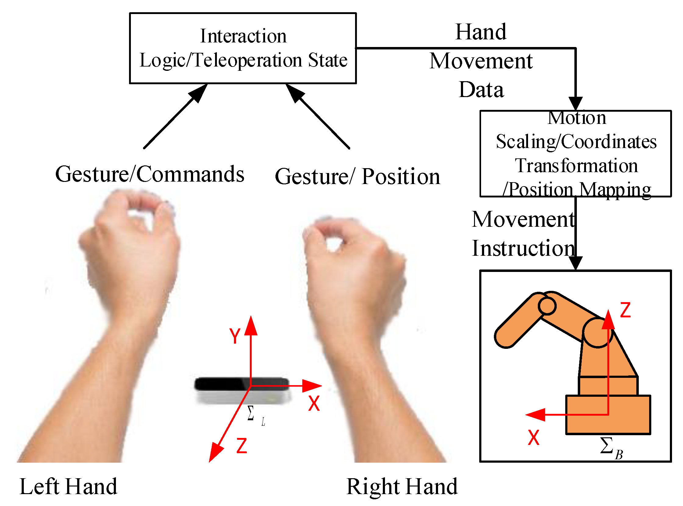
2.2. Hand-Robot-Tool Mapping

The typical teleoperation configuration is shown in Figure 3. An operator faces the robot with leap motion in front of him/her. There are several coordinate frames involved in this system, including the robot base frame Σ B , robot tool frame Σ T , and leap motion frame Σ L .
The robot can be guided in different frames—a base/tool/leap motion frame. In this paper, it is assumed that all the robot is guided along the robot base frame. Although physically, Σ L and Σ B are located at different places, they can be treated as sharing the same origin point because what matters is the relative motion instead of absolute movement.
The teleoperation is realized in an incremental way. Before each continuous movement, the teleoperation controller records the initial position of the robot tool Σ B r 0 and hand Σ L P 0 . At time t, the new hand position Σ L P t can be mapped to a robot with
Σ B r t = Σ B r 0 + Σ B R Σ L × Σ L P t Σ L P 0 ,
where Σ B R Σ L is the rotation matrix between Σ B and Σ L and Σ B R Σ L = 0 0 1 1 0 0 0 1 0 .
It is noticeable that the initial positions can be updated during the teleoperation, so the hand is not bounded by the working range of the leap motion sensor. It can be reset by renewing the mapping origins.

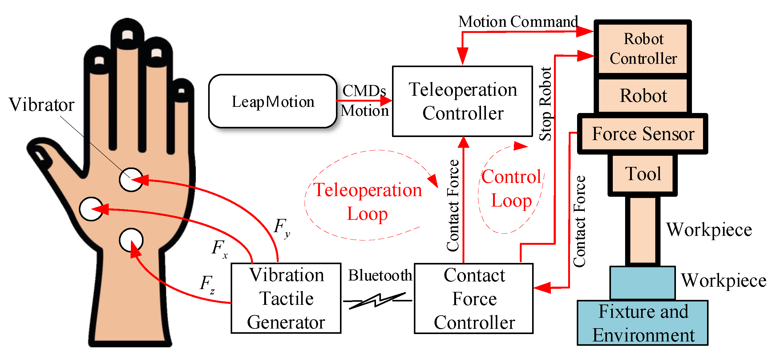
2.3. Force Feedback Loop

During the working process of the robot, such as assembly, it is unavoidable that one part contacts other parts. Sensing, controlling and learning contact force are an essential parts of the compliant teleoperation platform. Firstly, the contact force is feedback to the operator to avoid damaging the robot and the parts; secondly, the contact force usually contains skill knowledge of assembly process, which is a key to the knowledge transferring between human and robots.
According to the characters of the gesture-based teleoperation, a vibration/tactile based contact force feedback system is proposed to provide the operator with telepresence experience. As shown in Figure 4, the contact force is detected by the force sensor located between the robot tool and wrist. The force signals are directly fed in the force controller, which is a component connecting two loops—the teleoperation loop and the control loop, where passive and active force control is realized. The forces are sent to the vibration tactile generator, which will then drive three micro vibrators located on the hands. The vibration frequency is proportional to the amplitude of contact forces. The operator can “feel” the force direction and values by the vibration patterns. Then, the user can adjust their demonstration to ensure a proper skill is conducted. The inner control loop is a fail-safe mechanism, which guarantees the safety of the robot and parts when the operator does not regulate the force well. A threshold force is set. Once the contact force exceeds this threshold, the robot motion is limited; i.e., the robot can only be commanded to move in the reverse direction.

3. Gesture-Based Teleoperation System for Robot Motion

In the previous section, the development of physical interfaces for gesture-based teleoperation platform was described. However, because of the roughness and uncertainty of human motion, and thus the complexity of the actual tasks, it is still not possible to use those interfaces to teleoperate complex compliant skills, such as assembly. In this section, the above interfaces are further refined to meet such requirements and integrate them into the system. Figure 5 shows the block diagram of the proposed gesture-based teleoperation system.

3.1. Gesture Language Library and Interaction Logic

There are two main operations in the teleoperation—changing system state and relocating robot position. In order to achieve those two goals simultaneously, the following dual hands interaction logic is introduced.

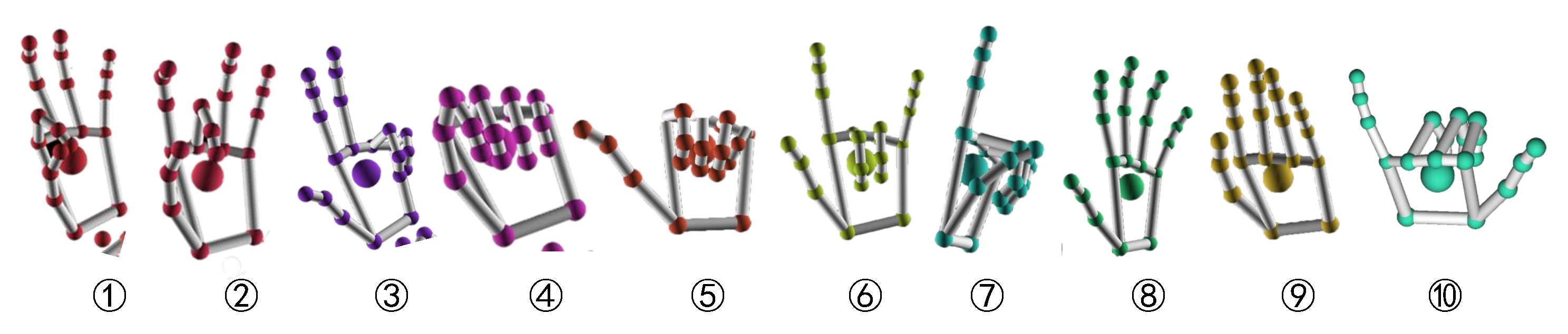
3.1.1. Gesture Library

As shown in Figure 6, both left and right hands are used to operate the robot. The left hand is used to generate gesture commands to change robot/system states, while the right hand is used to move the robot. There are thousands of static and dynamic gestures. In order to reduce system complexity, an assembly gesture library was designed to meet specific requirements. The index, name and meaning of gestures are given in Table 1, and the corresponding predefined static gestures are shown in Figure 7.

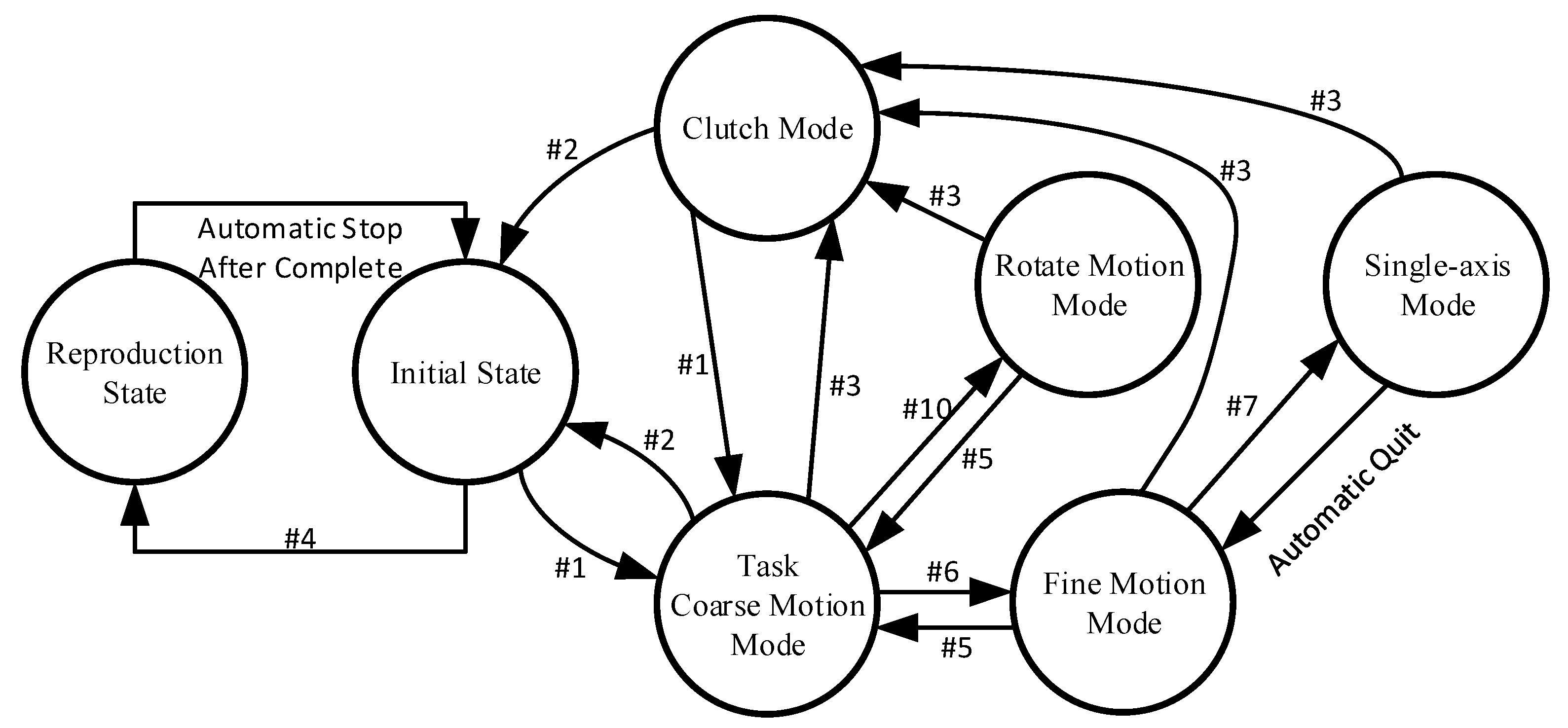
3.1.2. Interaction Logic

Based on the above gesture library, it is able to coordinate different motion modes and system states. In this paper, a finite state machine (FSM) is used to represent the system states: initial mode, coarse motion mode, fine motion mode, single-axis mode, clutch mode and reproduction state. Their switching conditions are shown in Figure 8.
The above modes were designed according to the requirements of assembly skills. Because the assembly process involves contact between parts, considering the uncertainties and unsteadiness in hands motion, a 1:1 mapping will directly transfer the disturbances into the robot motion, which may generate huge contact forces and cause serious damages for robot and parts. Therefore, in this paper, coarse, fine, single-axis motion modes are proposed. When the robot moves in a large free space, it is desirable to use coarse mode to improve the demonstration efficiency; when the robot moves in a small space or requires to contact the parts, it is essential to use fine motion mode to improve the teleoperation accuracy and system safety.
Many assembly processes, such as insertion, pick and placing operations, all include a linear movement along one direction. Therefore, a single-axis mode was introduced to increase the robustness of such motions. The clutch mode was proposed to achieve two goals—reducing teleoperation difficulty and increasing the motion range. When teleoperating a complex task, the operator may need a rest or to split the whole task into several subtasks. In the clutch mode, the robot stands still and the data acquisition is stopped. The operator can leave and then come back to continue later. The other reason is to increase the motion range. The leap motion has a limited sensing range. However, the robot may need to operate a part that is far away. The clutch mechanism provides a means to reset the mapping origins in (3). When in clutch mode, the operator can relocate his/her hands. Once switching back to motion mode, the new mapping origins are recorded, and the large movements can be realized in pieces by renewing the origins. The process is similar to operating the mouse on a small mouse pad.
Initially, the teleoperation platform is in standby mode. Once a start task gesture is detected, it will switch to motion mode with coarse motion. Then, it can be clutched using clutch gesture and switch to fine motion mode using fine motion gesture. In fine motion mode, once the single axis motion gesture is held, the robot will go into single-axis mode. When a stop task gesture is detected, the system will go back to the initial state. A reproduction gesture will trigger the learning process, and then the robot will repeat the learn motion autonomously. The gripper opens, and close gestures are active throughout the teleoperation process.

3.2. Hand/Tool Motion Scaling and Control

3.2.1. Motion Scaling

Fine and Coarse is realized by introducing a scaling coefficient in the mapping Equation (4).
Σ B r t = Σ B r 0 + s × Σ B R Σ L × Σ L P t Σ L P 0 ,
where s is the scaling coefficient, and by using different values, the human hand motions can be zoomed in or out. In coarse mode, s > 1 is used to let the robot move quickly from one position to another; in fine mode, s < 0.1 is used to let the robot moves in a small range with a small step size to avoid overshooting.

3.2.2. Single-Axis Motion

In some circumstances, the robot is required to move along an axis. In order to increase the robustness, a single-axis motion mechanism is proposed. During the demonstration, in t and t + 1 time steps, suppose the hand positions are Σ L P t and Σ L P t + 1 . The offset value is
Δ P t + 1 = Δ x t + 1 Δ y t + 1 Δ z t + 1 = Σ L P t + 1 Σ L P t .
The gradient, i.e., the axis with maximum offset, is treated as the desired movement direction. Ignoring other movement, one gets
Δ P ¯ t + 1 = Δ x t + 1 0 0 T Δ x t + 1 = max Δ P t + 1 0 Δ y t + 1 0 T Δ y t + 1 = max Δ P t + 1 0 0 Δ z t + 1 T Δ z t + 1 = max Δ P t + 1 .
It is noticeable that in single axis mode, the mapping Equation (4) cannot be used. The first reason is that the offset is evaluated between t and t + 1 instead of t 0 . The second reason is that the accumulation of ignored movements may cause serious negative effects when the principal axis changes. Therefore, Equation (4) was modified into
Σ B r t + 1 = Σ B r t + s × Σ B R Σ L × Σ L Δ P ¯ t + 1 ,
where Σ B r t and Σ L Δ P ¯ t + 1 are updated in each step to remove the accumulation effect.

3.3. Active Force Control
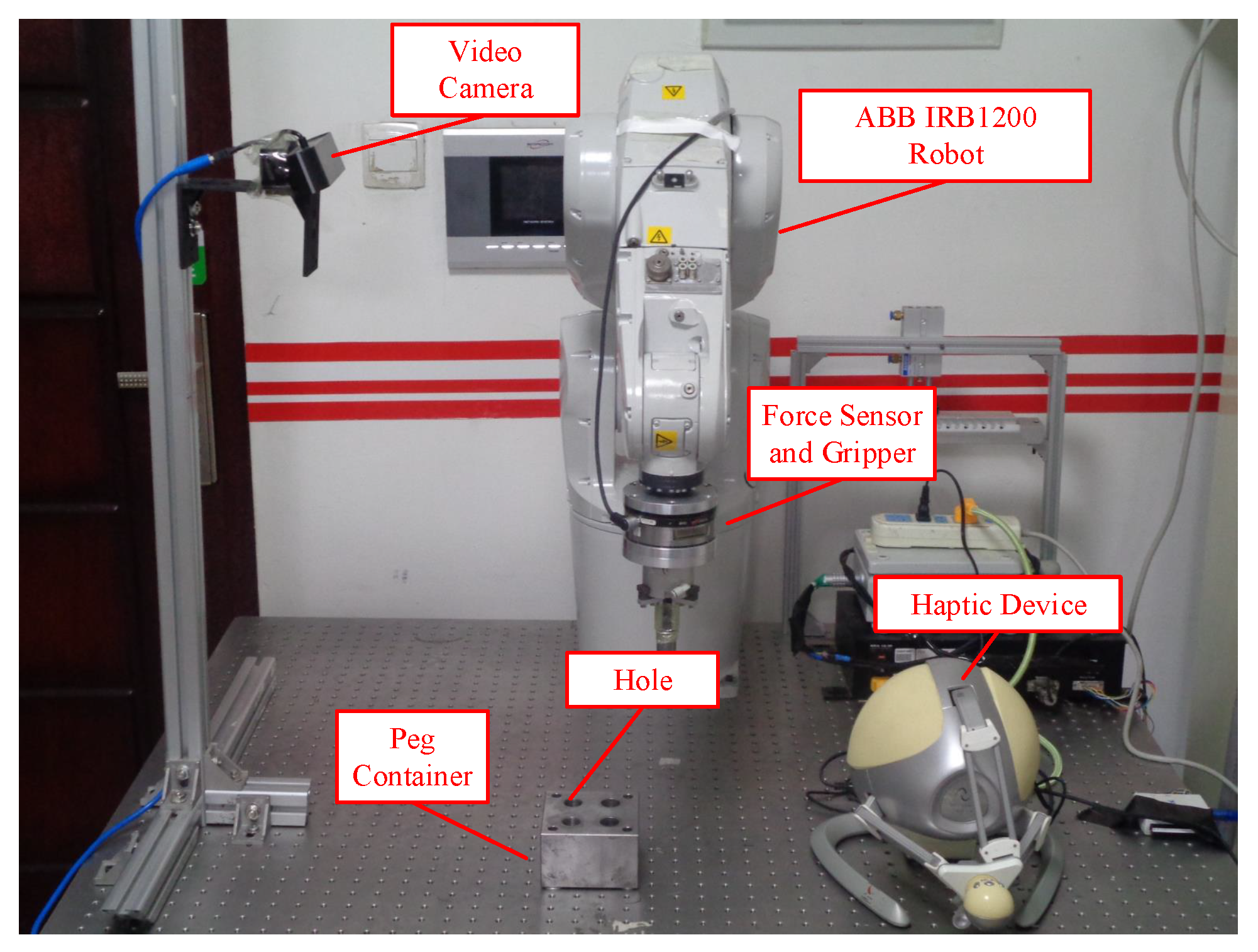
In order to guarantee the safety of the robotic system, the operator’s motion command is filtered in the inner force control loop according to the following law.
Σ B r ¯ t = K f Σ B × r t + I K f Σ B × r t 1 ,
where
K f Σ B = k x 0 0 0 k y 0 0 0 k z ,
is a weight matrix indicating whether the given command is acceptable. The elements are
k i = 1 F i < F t h e s h o l d 0 F i F t h e s h o l d i = x , y , z ,
where F t h e s h o l d is the predefined threshold contact force. It can be determined by the robot capacity and part materials. Also, the scaling coefficient s is related to this value. If the material is stiff, it is better to use a smaller s to ensure the contact force will not exceed F t h e s h o l d in a single step.
As shown in Figure 4, there is a connection between the force controller and the robot controller. It is a protective mechanism in extreme conditions. The force controller continuously monitors the analog force signals. Once the contact force exceeds the predefined value F m a x , a “STOP ROBOT” signal is sent to the robot controller immediately. Different from the above active force control, it is a reactive action with minimum delay. After triggering, the robot will not respond to the operation until performing a manual recovery.
This extreme state may be triggered when the robot moves with a large step size toward an obstacle. It can be avoided by using fine motion mode and moving the hands slowly.

4. Experiments

In order to verify the effectiveness of the gesture-based teleoperation system, the system was implemented on a platform shown in Figure 9a. The platform is based on an industrial robot manipulator: ABB IRB1200, which can carry a payload of up to 7 kg with a reach of 700 mm. The robot is mounted on the workbench. It is equipped with an ATI six DOF force/torque sensor and corresponding force control functionality. A pneumatic gripper was attached to the force sensor to pick up peg and do the peg-in-hole assembly work. The hole was installed at an arbitrary location within the workspace of the manipulator. The diameter of the peg was 12.00 mm, and the clearance between the peg and hole was 0.08 mm. The length of the peg was 100.00 mm and the depth of the hole was 60.00 mm.
An external computer was used as the teleoperation controller. The leap motion sensor was connected to this computer. Its tasks included recognizing hand gestures, tracking hand motions, controlling the interaction logic and recording the demonstrations.
The computer and the robot IRC5 controller communicate with each other through Ethernet. The computer sends out motion commands and receives feedback robot states. The robot is preprogrammed with the capability of responding to the motion commands and feeding back its states.

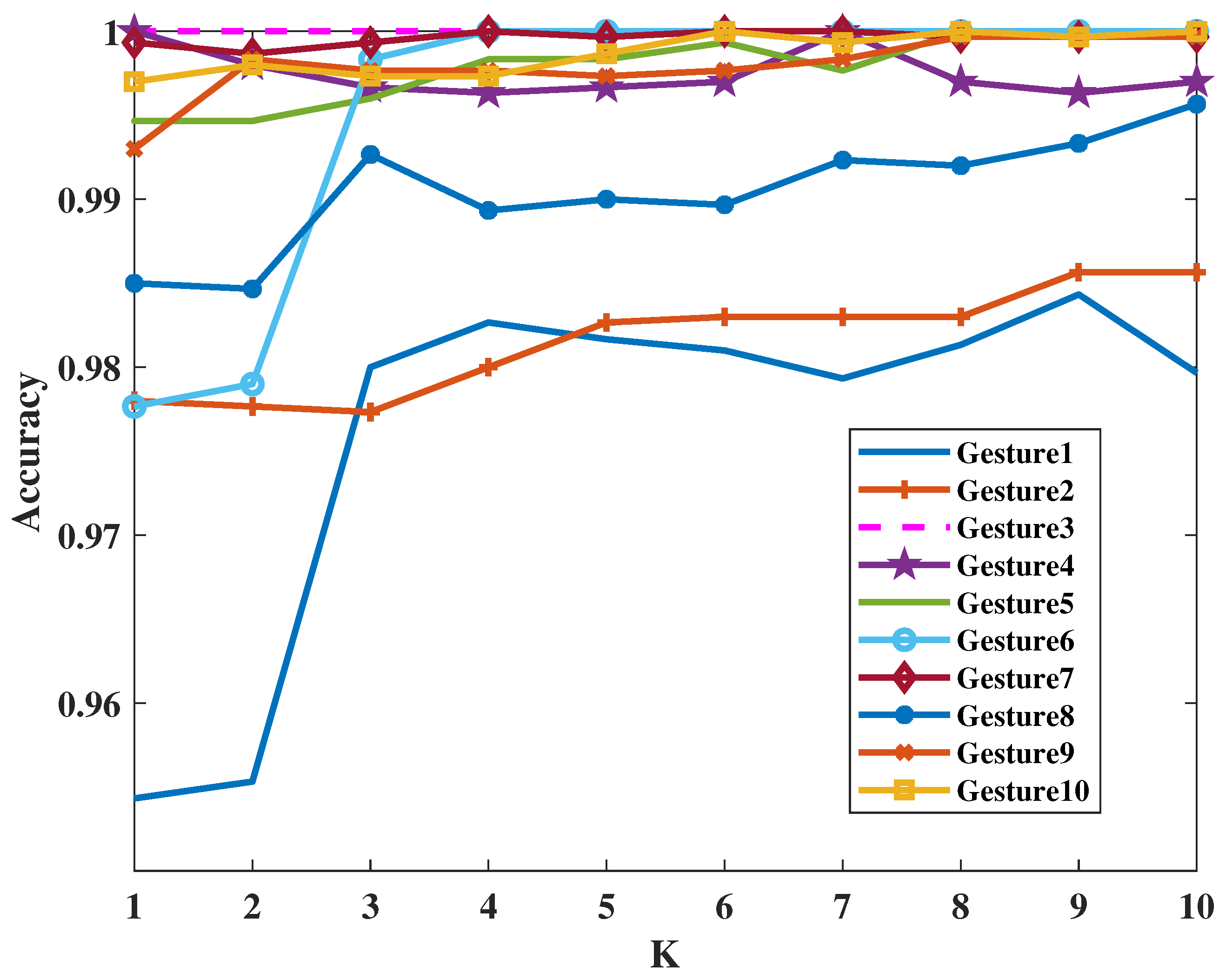
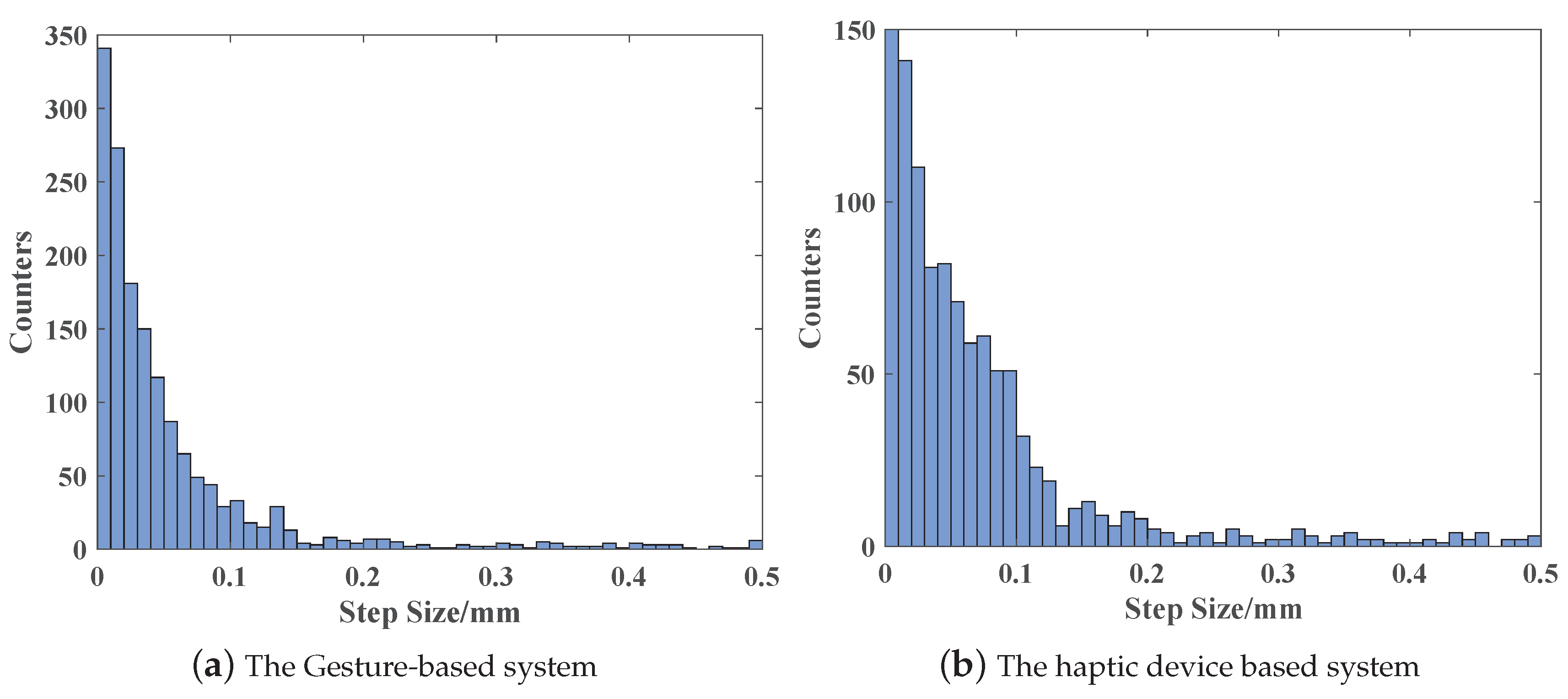
4.1. Gesture Recognition Results

For each gesture, 8000 samples were collected. Those samples were obtained from four different persons with different hand sizes. The 8000 samples were randomly sorted and then sliced into two parts: 5000 samples for modeling and 3000 samples for evaluation. In GMM, the number of components was a hyper-parameter, which should be determined first. In this paper, GMMs with different K values were evaluated by using the Scikit-learn machine learning library [32], and the covariance “tied” was chosen.The relevant specific code can be found at https://github.com/pz10150127/Gesture_GMM. The results are shown in Figure 10.
As shown in Figure 10, the recognition rate for each gesture (M i ) was plotted. It is clearly visible that K indeed affects the modeling accuracy. Higher K leads to a higher rate. To balance the accuracy and computational complexity, K = 3 was used in the gesture-based demonstration platform. The average recognition rate was more than 98%. The detection time was 3 ms on an Intel Core I7-8650U at 1.9 GHz CPU computer, which is enough for the application.

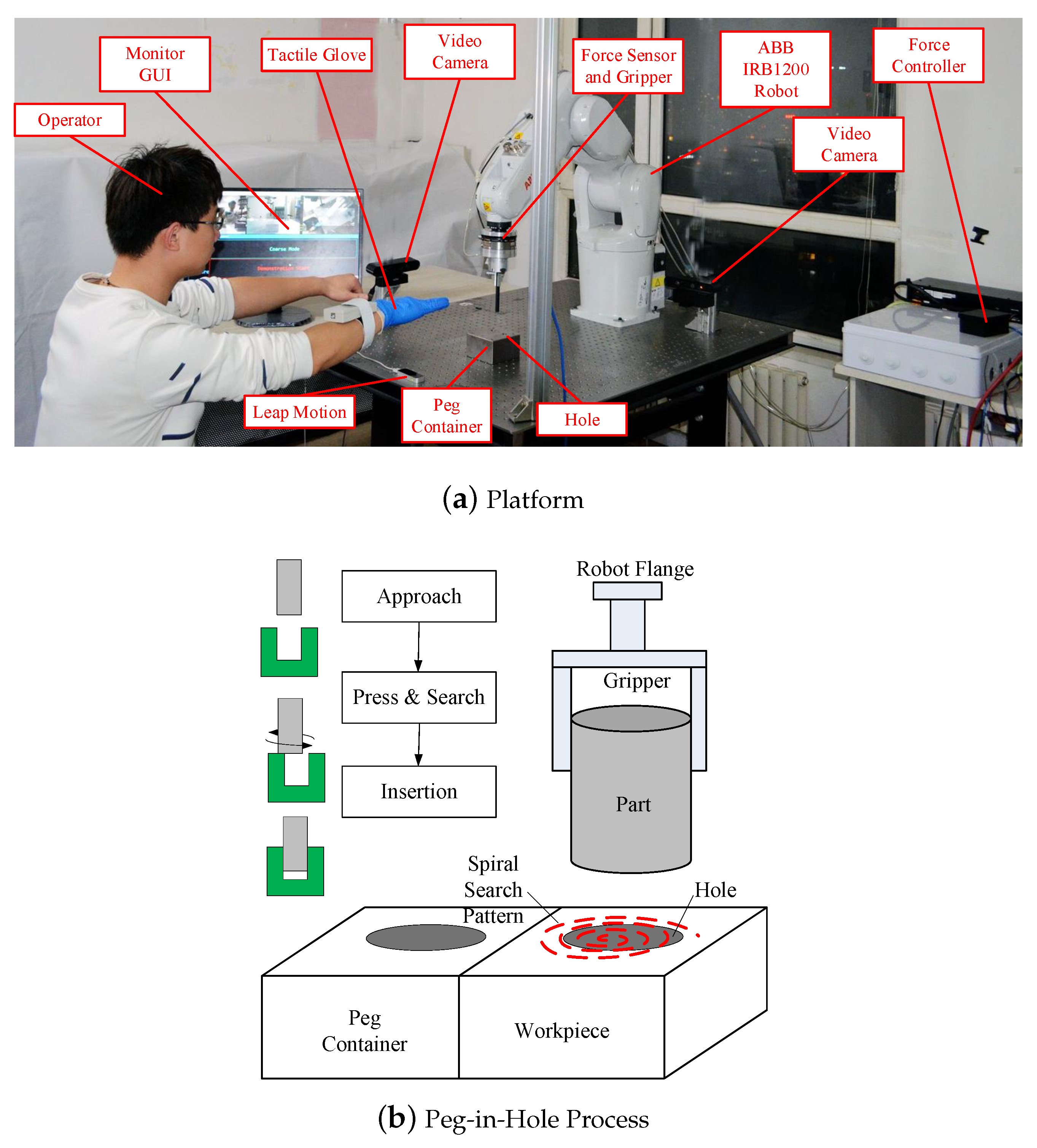
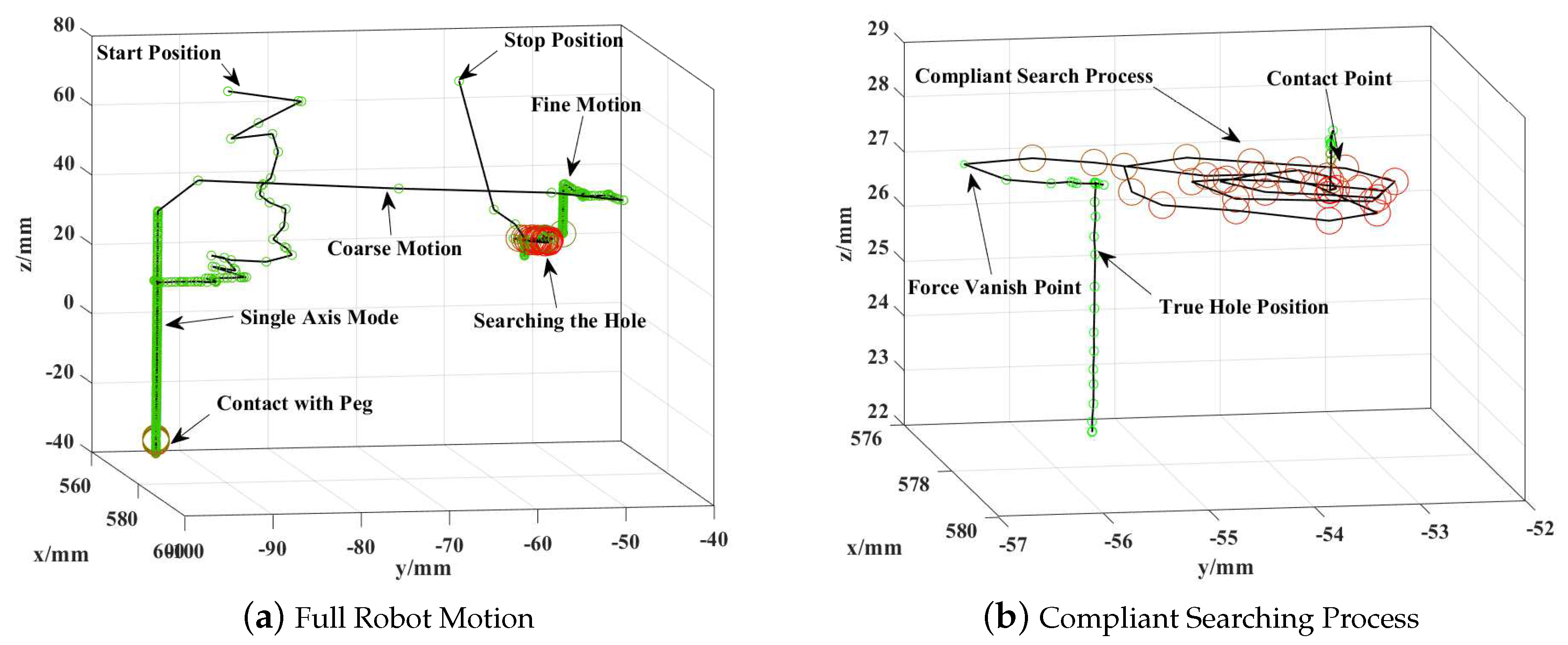
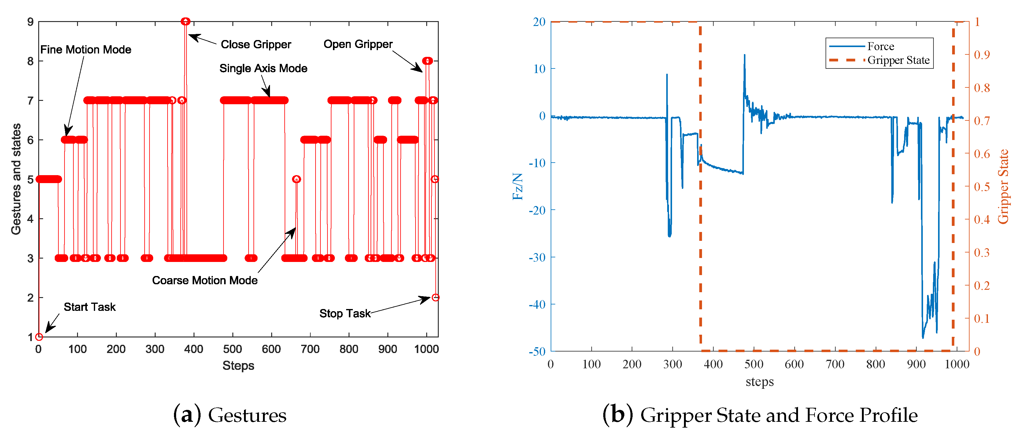
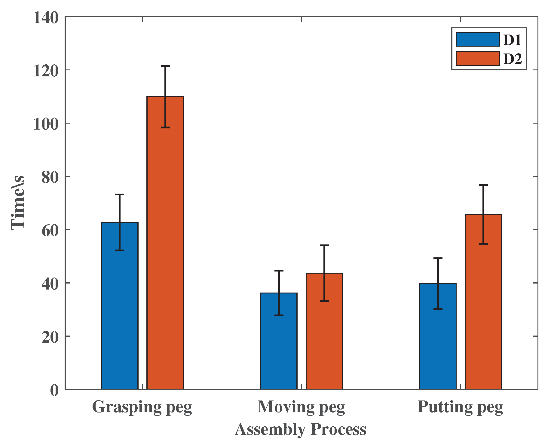
4.2. Case Study of Peg-In-Hole Process

The gesture-based teleoperation system was used to show the robot how to execute the pick-and-place and peg-in-hole task. The platform is shown in Figure 9a. The whole process is as follows:
  • Move the robot gripper above the peg;
  • Move the robot gripper downward until contact;
  • Close the pneumatic gripper;
  • Move the robot gripper upward until the peg is higher than container;
  • Move the peg above the hole;
  • Move the peg downward until contact;
  • Move along a spiral pattern to search the hole while pressing the surface; this process continues until the contact force disappears;
  • Move the peg downward;
  • Open the robot gripper to release the peg.
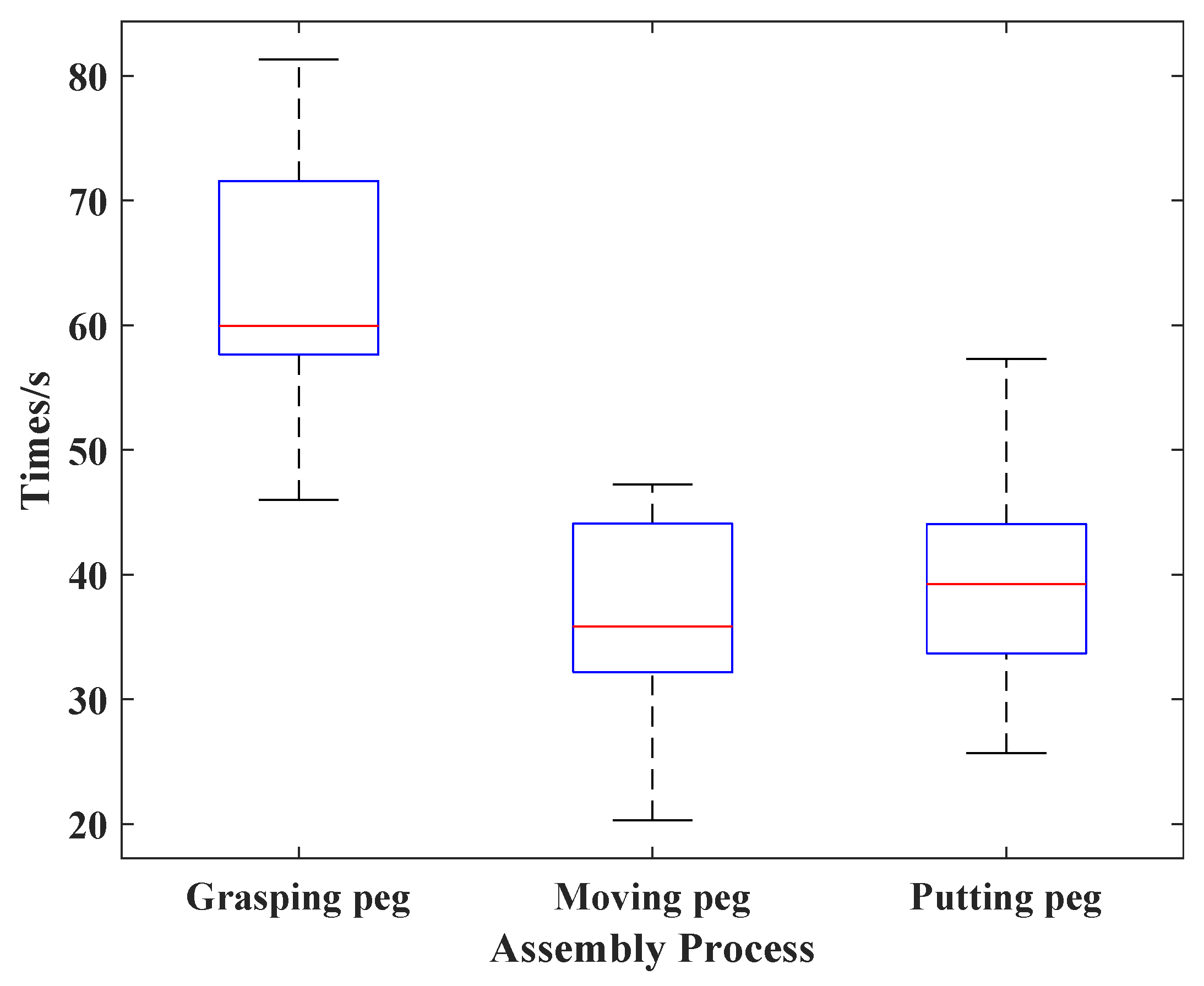
Steps 2, 6 and 7 are related to contact force. The force is a vital signal indicating the assembly state. In step 2 the contact signal means the gripper surrounds the peg, and there is no gap in the vertical direction; in step 6, similarly to the step 2, the contact force signal means the peg contacts the hole’s surface, which means the peg misses the right hole position. It is ubiquitous in the tight tolerant assembly process, so a compliant searching process is needed. Reference [33] gives a detailed discussion of the searching process. In step 7, a search force is necessary for a successful hole searching process. It can provide a judging signal when finding the right hole position. The signal may be that the contact force disappears, or the contact force suddenly drops in the downward direction.
During the pick-and-place and peg-in-hole process, the force threshold F t h r e s h o l d was set to 40 N. The scaling coefficient s was chosen as 0.05 in fine mode and 1.0 in the coarse mode. The maximum force F m a x was set to 70 N.

4.2.1. Results

It takes less than an hour to train two operators to use the gesture-based system, including how to make the right gestures, how to switch modes and how to accurately control the robot movement. And it requires more than 10 min for the operator to complete an assembly task at the beginning of the training. After several training sessions, the assembly task can be completed in 1.5 min. Although the speeds were different, all tasks were successfully accomplished.
Ten sets of experiments were done by two operators. As shown in Figure 11, the average time for grabbing the axis was 62.72 s and its standard deviation was 10.51 s, the average time for moving the axis was 36.19 s and its standard deviation was 8.41 s; and the time for putting the peg in the hole was 39.74 s and its standard deviation was 9.48 s. Because of the difference in physical structure of human and robot, it was a bit slower than manual operation. After learning the tasks through GMM/GMR method [34], the robot can quickly reproduce this task.
One of the recorded robot motions is shown in Figure 12; the small green circles stand for the robot position in free space, while the big red circles are positions where contact force was detected. Figure 12a shows a full robot motion from start position to stop position. Initially, it was in coarse motion mode. Because of the unsteadiness of human motion, the robot motion also had a significant variation. This variation is not a serious problem because it can be smoothed in the learning from the demonstration process by averaging techniques.
When the robot was close to the peg, it was switched into fine motion mode. The step size reduced, and the points were dense compared to coarse motion mode. After a series of adjustments, the robot moved above the peg, and the single-axis mode was used. The robot moved along the vertical direction until the contact force was detected.
After closing the gripper, the robot started to lift the peg out of the container. Because the gripper-peg combination was longer than the gripper, the lift attitude was higher than the previous gripping process. Once the peg was out of the container, it was switched into coarse motion mode again. The peg was swiftly moved above the hole. After adjusting the position in fine mode, the peg was driving downward in single axis mode until contact occurred. This process can be clearly seen in Figure 12b. The dense red circles are points in the hole searching process when the robot movds along a horizontal search pattern while keeping contact with the hole’s surface. Finally, once the contact force vanished, it was switched into the fine motion mode and single-axis mode to insert the peg into the hole and release the peg then. Finally, the gripper was lifted with coarse motion mode and returned to the stop position.
Figure 13a shows the used gestures. The values represent specific actions, as shown in Table 1. It can be seen that coarse mode, fine mode and single-axis mode are frequently used to adapt the assembly skills and sensor ranges. Gripper open/close gestures were used twice to pick and place the peg.
Figure 13b shows the forces measured during the teleoperation. The compliant assembly skills can be located on this figure. The contact force in the process of moving the robot gripper downward appears at around step 450; the search force in the process searching hole appears at around step 950. Owing to human uncertainties, the locating errors and the friction between peg-container and peg-hole generated additional forces. The pulse drag force (positive) at step 280 and 500 was caused by those frictions when lifting motion happens, and multiple demonstrations can eliminate this. It was noticed that the contact force was limited around 40 N, which proves the effectiveness of the proposed passive and active force control mechanism.
The above peg-in-hole process shows that the gesture-based interaction system can be used to teleoperate the robot with compliant and complex assembly skills. The operator can sense the contact force and select appropriate motion mode to balance efficiency and accuracy.

4.2.2. Analysis

In order to illustrate the effectiveness of the proposed system, as shown in Figure 14, an assembly system based on a haptic device was built for comparison. The haptic device is the Novint Falcon, which is a relatively inexpensive haptic device, and it was selected to offer force feedback while allowing the control of the end-effector with minimal effort [35]. It has only four buttons, which can only define four working modes; namely, coarse motion mode, fine motion mode, clutch mode and claw open/close gripper mode. In this experiment, two operators were used to perform 10 sets of experiments to accomplish the same assembly task.
As shown in Figure 15, the gesture-based teleoperation system costs less time than the system based on the haptic device. In the stage of grasping the peg, since the center of the gripper needs to be aligned with the peg, the single-axis motion mode is crucial. Because the haptic device based system without the single-axis motion mode, it needs to adjust the position of the gripper many times, so it takes more time to adjust the position of the gripper. When moving the peg, the haptic device based system needs to clutch more times than the gesture system because its working range is less than the leap motion. During putting the peg in the hole, while haptic-based systems can provide better force feedback, it needs more time to adjust the position because there is no single-axis mode.
Figure 16 shows the distribution of the step size in the teleoperation. It can be seen that the gesture-based system and the haptic device based system have a similar distributions: most of the step sizes were less than 1 mm, and some of them were smaller than 0.1 mm. A smaller step size means the position can be precisely adjusted, and even human hand motions are uncertain and noisy. It was noticed that the step size was related to several factors, such as the scaling coefficient and the human hand’s velocity. The operator should choose fine motion mode and slow down their moving speed to improving accuracy and system safety.
It can be seen from the above comparison that the gesture-based teleoperation system can perform high-precision operations due to good scalability; it is possible to select a suitable working mode to complete the task faster. Therefore, the proposed gestured based teleoperation system provides an alternative option for portable, precise and compliant teleoperation methods.

5. Conclusions and Future Work

This paper proposes a novel gesture-based teleoperation system for compliant robot motion. In order to overcome the limitations of human motion accuracy, resolution and sensor work range, the paper introduces new interaction logic, scalable human-robot motion mapping mechanism and single axis mode to balance teleoperation efficiency and accuracy. In order to meet the requirements of complaint assembly skill, a vibration based force feedback system was developed to let the operator feel the contact force. An active force control mechanism was also designed to restrict the contact force within a safe range. The gesture-based teleoperation system was tested with a pick-and-place and peg-in-hole case study. The results prove its effectiveness and feasibility in tight, tolerant and complaint assembly tasks. In the future, we will focus on more complex complaint robot motions to complete more advanced tasks.

Author Contributions

Literature search, software, data curation and writing—original draft, W.Z. and M.T.; data interpretation, H.C., L.Z. and M.T.; methodology, L.H. and L.Z.; writing—review and editing, H.C., L.H. and C.X.

Funding

This work was supported in part by the Natural Science Foundation of Liaoning Province under grant number 20180520003, the Natural Science Foundation of China under grant number 61573093 and U1613205, the Fundamental Research Funds for the Central Universities under grant number N18.

Acknowledgments

We thank Xingchen Li for his comments which substantially improved the quality of this paper.

Conflicts of Interest

The authors declare no conflict of interest.

References

  1. Wen, G.; Xie, Y.C. Research on the tele-operation robot system with tele-presence. In Proceedings of the 4th International Workshop on Advanced Computational Intelligence (IWACI 2011), Beijing, China, 7–10 August 2011; pp. 725–728. [Google Scholar] [CrossRef]
  2. Romano, D.; Donati, E.; Benelli, G.; Stefanini, C. A review on animal-robot interaction: From bio-hybrid organisms to mixed societies. Biol. Cybern. 2019, 113, 201–225. [Google Scholar] [CrossRef] [PubMed]
  3. Ando, N.; Kanzaki, R. Using insects to drive mobile robots—Hybrid robots bridge the gap between biological and artificial systems. Arthropod Struct. Dev. 2017, 46, 723–735. [Google Scholar] [CrossRef] [PubMed]
  4. Bozkurt, A.; Lobaton, E.; Sichitiu, M.L. A Biobotic Distributed Sensor Network for Under-Rubble Search and Rescue. IEEE Comput. 2016, 49, 38–46. [Google Scholar] [CrossRef]
  5. Breazeal, C.; Dautenhahn, K.; Kanda, T. Social Robotics; Springer International Publishing: Berlin, Germany, 2016. [Google Scholar]
  6. Cui, J.; Tosunoglu, S.; Roberts, R.; Moore, C.; Repperger, D.W. A review of teleoperation system control. In Proceedings of the Florida Conference on Recent Advances in Robotics, Boca Raton, FL, USA, 18–20 June 2003; pp. 1–12. [Google Scholar]
  7. Xu, Z.; Fiebrink, R.; Matsuoka, Y. Virtual therapist: A Phantom robot-based haptic system for personalized post-surgery finger rehabilitation. In Proceedings of the 2012 IEEE International Conference on Robotics and Biomimetics (ROBIO), Guangzhou, China, 11–14 December 2012; pp. 1662–1667. [Google Scholar]
  8. Sanfilippo, F.; Weustink, P.B.T.; Pettersen, K.Y. A Coupling Library for the Force Dimension Haptic Devices and the 20-sim Modelling and Simulation Environment. In Proceedings of the 41st Annual Conference of the IEEE Industrial Electronics Society (IECON), Yokohama, Japan, 9–12 November 2015. [Google Scholar]
  9. Shimada, N.; Shirai, Y.; Kuno, Y.; Miura, J. Hand gesture estimation and model refinement using monocular camera-ambiguity limitation by inequality constraints. In Proceedings of the IEEE International Conference on Automatic Face and Gesture Recognition, Nara, Japan, 14–16 April 1998; pp. 268–273. [Google Scholar]
  10. Li, X.; An, J.H.; Min, J.H.; Hong, K.S. Hand gesture recognition by stereo camera using the thinning method. In Proceedings of the International Conference on Multimedia Technology, Hangzhou, China, 26–28 July 2011; pp. 3077–3080. [Google Scholar]
  11. Ren, Z.; Yuan, J.; Meng, J.; Zhang, Z. Robust Part-Based Hand Gesture Recognition Using Kinect Sensor. IEEE Trans. Multimed. 2013, 15, 1110–1120. [Google Scholar] [CrossRef]
  12. Wei, Q.; Yang, C.; Fan, W.; Zhao, Y. Design of Demonstration-Driven Assembling Manipulator. Appl. Sci. 2018, 8, 797. [Google Scholar] [CrossRef] [Green Version]
  13. Côté-Allard, U.; Fall, C.L.; Campeau-Lecours, A.; Gosselin, C.; Laviolette, F.; Gosselin, B. Transfer learning for sEMG hand gestures recognition using convolutional neural networks. In Proceedings of the 2017 IEEE International Conference on Systems, Man, and Cybernetics (SMC), Banff, AB, Canada, 5–8 October 2017; pp. 1663–1668. [Google Scholar]
  14. Weichert, F.; Bachmann, D.; Rudak, B.; Fisseler, D. Analysis of the Accuracy and Robustness of the Leap Motion Controller. Sensors 2013, 13, 6380–6393. [Google Scholar] [CrossRef] [PubMed]
  15. Placidi, G.; Cinque, L.; Polsinelli, M.; Spezialetti, M. Measurements by A LEAP-Based Virtual Glove for the Hand Rehabilitation. Sensors 2018, 18, 834. [Google Scholar] [CrossRef] [PubMed] [Green Version]
  16. Bassily, D.; Georgoulas, C.; Guettler, J.; Linner, T.; Bock, T. Intuitive and Adaptive Robotic Arm Manipulation using the Leap Motion Controller. In Proceedings of the Isr/robotik 2014; International Symposium on Robotics, Munich, Germany, 2–3 June 2014; pp. 1–7. [Google Scholar]
  17. Hernoux, F.; Béarée, R.; Gibaru, O. Investigation of dynamic 3D hand motion reproduction by a robot using a Leap Motion. In Proceedings of the Virtual Reality International Conference, Laval, France, 8–10 April 2015; pp. 1–10. [Google Scholar]
  18. Jin, H.; Zhang, L.; Rockel, S.; Zhang, J.; Hu, Y.; Zhang, J. Optical Tracking based Tele-control System for Tabletop Object Manipulation Tasks. In Proceedings of the IEEE/RSJ International Conference on Intelligent Robots and Systems, Hamburg, Germany, 28 September–3 October 2015; pp. 636–642. [Google Scholar]
  19. Jin, H.; Chen, Q.; Chen, Z.; Hu, Y.; Zhang, J. Multi-LeapMotion sensor based demonstration for robotic refine tabletop object manipulation task. CAAI Trans. Intell. Technol. 2016, 1, 104–113. [Google Scholar] [CrossRef] [Green Version]
  20. Despinoy, F.; Zemiti, N.; Forestier, G.; Sánchez, A.; Jannin, P.; Poignet, P. Evaluation of contactless human-machine interface for robotic surgical training. Int. J. Comput. Assist. Radiol. Surg. 2017, 13, 1–12. [Google Scholar] [CrossRef] [PubMed] [Green Version]
  21. Du, G.; Zhang, P.; Liu, X. Markerless Human–Manipulator Interface Using Leap Motion With Interval Kalman Filter and Improved Particle Filter. IEEE Trans. Ind. Inform. 2017, 12, 694–704. [Google Scholar] [CrossRef]
  22. Zhao, Y.; Al-Yacoub, A.; Goh, Y.M.; Justham, L.; Lohse, N.; Jackson, M.R. Human skill capture: A Hidden Markov Model of force and torque data in peg-in-a-hole assembly process. In Proceedings of the 2016 IEEE International Conference on Systems, Man, and Cybernetics (SMC), Budapest, Hungary, 9–12 October 2016; pp. 000655–000660. [Google Scholar]
  23. Zhang, K.; Shi, M.H.; Xu, J.; Liu, F.; Chen, K. Force control for a rigid dual peg-in-hole assembly. Assem. Autom. 2017, 37, 200–207. [Google Scholar] [CrossRef]
  24. Dennerlein, J.T.; Millman, P.A.; Howe, R.D. Vibrotactile feedback for industrial telemanipulators. In Proceedings of the Sixth Annual Symposium on Haptic Interfaces for Virtual Environment and Teleoperator Systems, ASME International Mechanical Engineering Congress and Exposition, Dallas, TX, USA, 16–21 November 1997; Volume 61, pp. 189–195. [Google Scholar]
  25. Raveh, E.; Portnoy, S.; Friedman, J. Adding vibrotactile feedback to a myoelectric-controlled hand improves performance when online visual feedback is disturbed. Hum. Mov. Sci. 2018, 58, 32–40. [Google Scholar] [CrossRef] [PubMed]
  26. Khasnobish, A.; Pal, M.; Sardar, D.; Tibarewala, D.N.; Konar, A. Vibrotactile feedback for conveying object shape information as perceived by artificial sensing of robotic arm. Cogn. Neurodyn. 2016, 10, 327–338. [Google Scholar] [CrossRef] [PubMed] [Green Version]
  27. Hussain, I.; Meli, L.; Pacchierotti, C.; Salvietti, G.; Prattichizzo, D. Vibrotactile Haptic Feedback for Intuitive Control of Robotic Extra Fingers. In Proceedings of the 2015 IEEE World Haptics Conference, Evanston, IL, USA, 22–26 June 2015. [Google Scholar]
  28. Cheok, M.J.; Omar, Z.; Jaward, M.H. A review of hand gesture and sign language recognition techniques. Int. J. Mach. Learn. Cybern. 2019, 10, 131–153. [Google Scholar] [CrossRef]
  29. Perezdelpulgar, C.J.; Smisek, J.; Rivasblanco, I.; Schiele, A.; Munoz, V.F. Using Gaussian Mixture Models for Gesture Recognition During Haptically Guided Telemanipulation. Electronics 2019, 8, 772. [Google Scholar] [CrossRef] [Green Version]
  30. Xuan, G.; Zhang, W.; Chai, P. EM algorithms of Gaussian mixture model and hidden Markov model. In Proceedings of the 2001 International Conference on Image Processing (ICIP), Thessaloniki, Greece, 7–10 October 2001; Volume 1, pp. 145–148. [Google Scholar]
  31. Watanabe, H.; Muramatsu, S.; Kikuchi, H. Interval calculation of EM algorithm for GMM parameter estimation. In Proceedings of the 2010 IEEE International Symposium on Circuits and Systems, Paris, France, 30 May–2 June 2010; pp. 2686–2689. [Google Scholar]
  32. Pedregosa, F.; Varoquaux, G.; Gramfort, A.; Michel, V.; Thirion, B.; Grisel, O.; Blondel, M.; Prettenhofer, P.; Weiss, R.; Dubourg, V.; et al. Scikit-learn: Machine Learning in Python. J. Mach. Learn. Res. 2011, 12, 2825–2830. [Google Scholar]
  33. Chen, H.; Zhang, G.; Zhang, H.; Fuhlbrigge, T.A. Integrated robotic system for high precision assembly in a semi-structured environment. Assem. Autom. 2007, 27, 247–252. [Google Scholar] [CrossRef]
  34. Li, X.; Cheng, H.; Liang, X. Adaptive motion planning framework by learning from demonstration. Ind. Robot 2019, 46, 541–552. [Google Scholar] [CrossRef]
  35. Cappa, P.; Clerico, A.; Nov, O.; Porfiri, M. Can force feedback and science learning enhance the effectiveness of neuro-rehabilitation? An experimental study on using a low-cost 3D joystick and a virtual visit to a zoo. PLoS ONE 2013, 8, e83945. [Google Scholar] [CrossRef] [PubMed]
Figure 1. Hand model used in leap motion and feature selection for hand gesture classification.
Applsci 09 05290 g001
Figure 2. Block diagram of the Gaussian mixture model (GMM) based hand gesture classification.
Applsci 09 05290 g002
Figure 3. The gesture-based assembly skill teleoperation platform and the corresponding coordinate frames.
Applsci 09 05290 g003
Figure 4. Block diagram of the proposed vibration-based force feedback and sensing system.
Applsci 09 05290 g004
Figure 5. Block diagram of the proposed gesture-based teleoperation system for robot motion.
Applsci 09 05290 g005
Figure 6. Interaction logic for the gesture-based teleoperation system.
Applsci 09 05290 g006
Figure 7. The predefined static gestures.
Applsci 09 05290 g007
Figure 8. Finite state machine (FSM) work-flow for the proposed gesture-based interaction logic. The label of the conversion condition is the index of the gestures in Table 1.
Applsci 09 05290 g008
Figure 9. Experimental platform. (a) Photo of the experimental platform. The gesture-based teleoperation interface was used to demonstrate a complete pick-and-place and peg-in-hole assembly task. (b) The compliant assembly skills in the peg-in-hole process.
Applsci 09 05290 g009
Figure 10. Hand gesture identification results versus GMMs with different K. Gesture 1 to Gesture 10 represent the ten gestures in Figure 7. To balance the accuracy and computational complexity, K = 3 was used in the gesture-based demonstration platform.
Applsci 09 05290 g010
Figure 11. The portion time for each part of the assembly process. The average time for grabbing the axis was 62.72 s and its standard deviation was 10.51 s; the average time for moving the axis was 36.19 s and its standard deviation was 8.41 s; and the time for putting the peg in the hole was 39.74 s and its standard deviation was 9.48 s.
Applsci 09 05290 g011
Figure 12. The recorded robot motions and force profile during the demonstration of a pick-and-place and peg-in-hole process. In fine motion mode, dense points were recorded. The big red circle indicates contact force was detected. From this figure, one can clearly see the robot motion trajectories and operation mode. (b) Partial of (a), which enlarges the compliant hole searching process.
Applsci 09 05290 g012
Figure 13. These two figures show changes of hand gestures, gripper states and contact forces.
Applsci 09 05290 g013
Figure 14. The experimental platform based on haptic device. The haptic device is a Falcon haptic device which has three degrees of freedom.
Applsci 09 05290 g014
Figure 15. Comparison of teleoperation time at each stage. D1 represents the gesture-based teleoperation system, and D2 denotes the system based on the haptic device.
Applsci 09 05290 g015
Figure 16. The distribution of the step size in the teleoperation.
Applsci 09 05290 g016
Table 1. The proposed gesture commands for teleoperation.
#NameMeanings
1Task StartStart a new task, from standby mode to task mode
2Task StopEnd a task, from task mode to standby mode
3Task ClutchClutch task, robot doesn’t response the motion command
4Start reproductionAutonomous Repeating the learned motions
5Coarse Motion ModeMoves with big motion scaling factor
6Fine Motion ModeMoves with small motion scaling factor
7Single-axis ModeMoves only along the gratitude direction
8Open GripperOpen the robot gripper or tool
9Close GripperClose the robot gripper or tool
10Rotation Motion ModeRotate the robot tool

