Integrated Design of Aerodynamic Performance and Structural Characteristics for Medium Thickness Wind Turbine Airfoil

Abstract
:1. Introduction
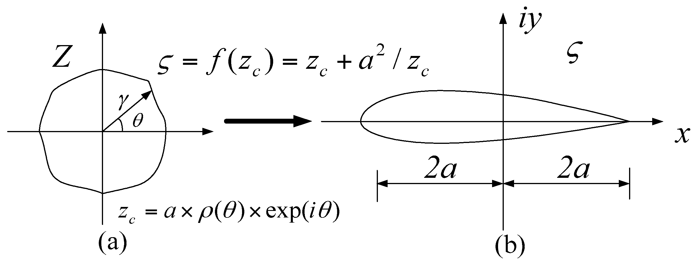
2. Airfoils Functional Integrated Express
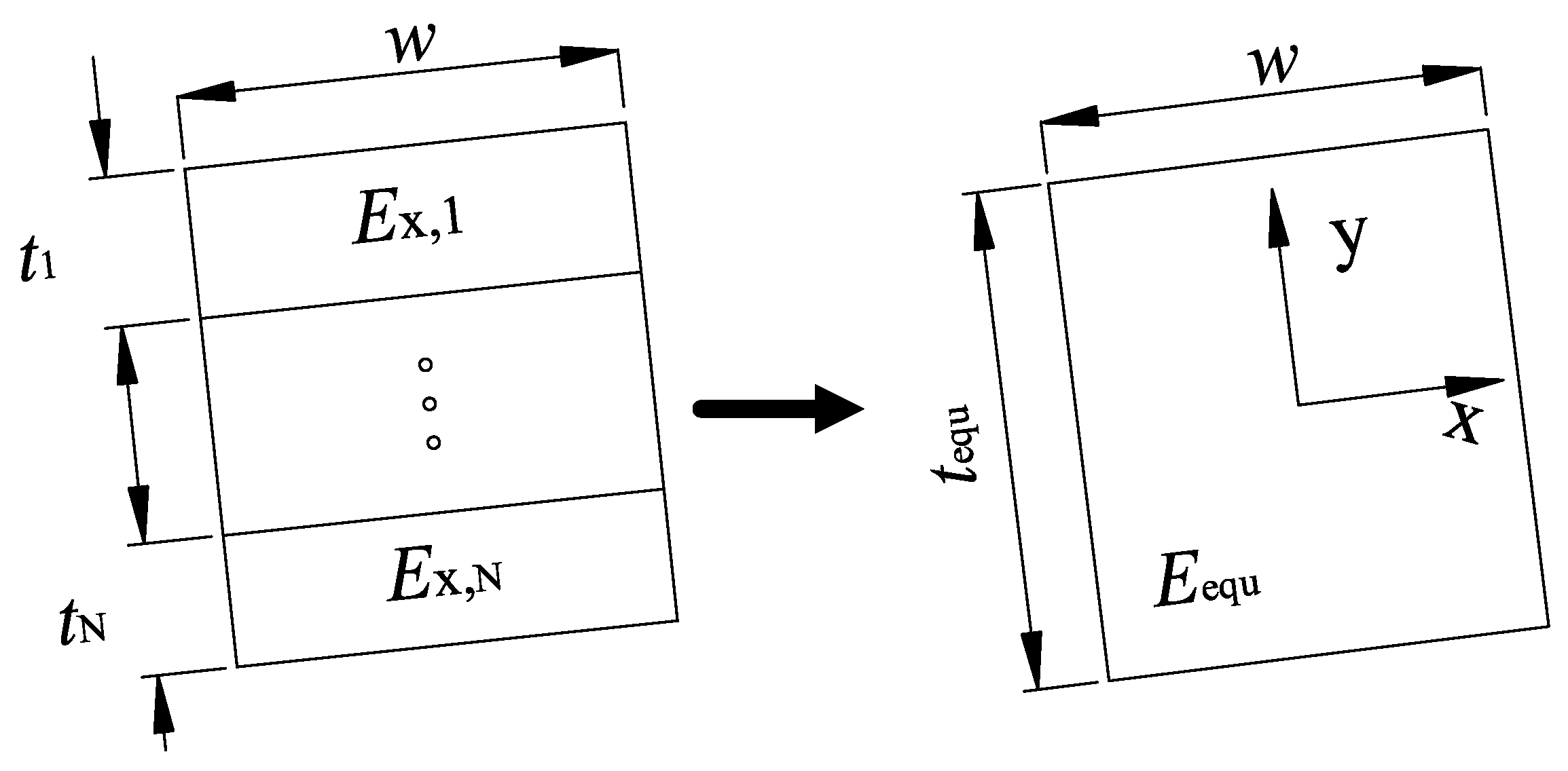
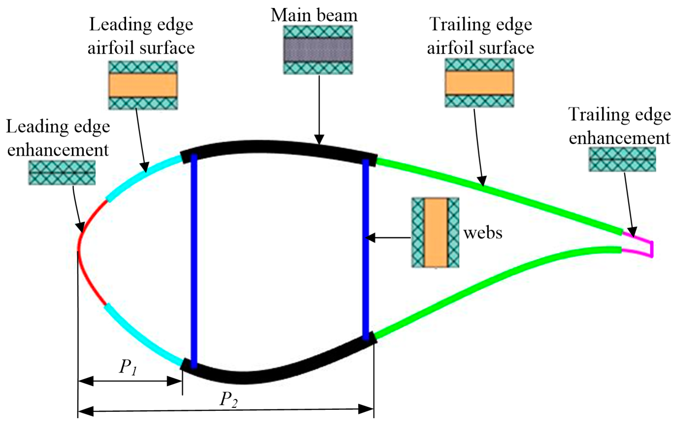
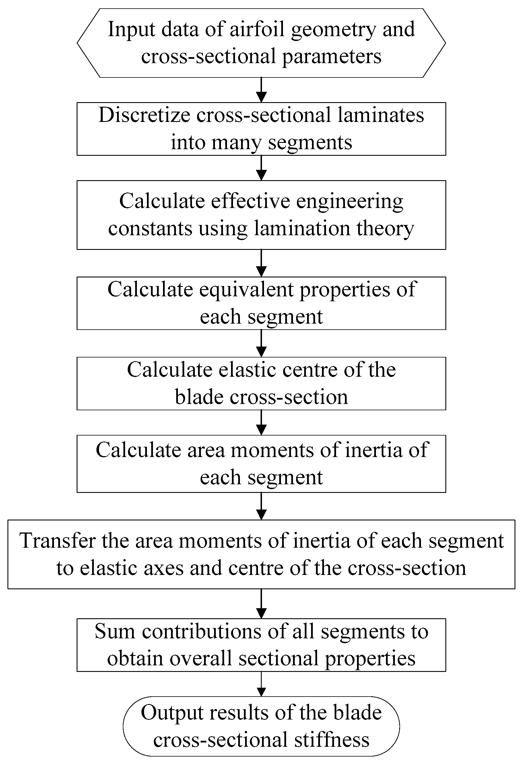
3. Stiffness Matrix Calculation of Composite Blade Section
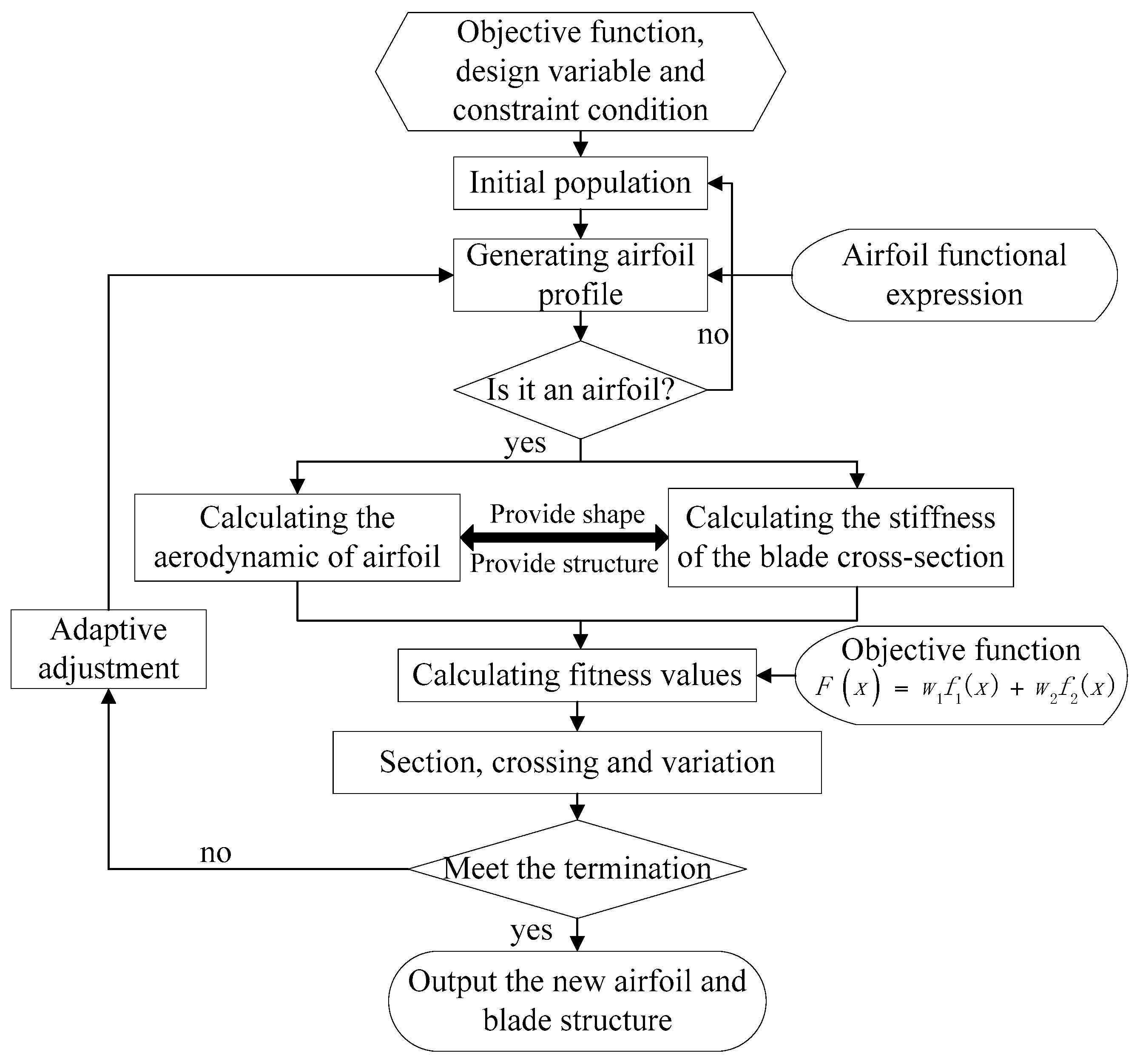
4. The Optimized Mathematical Model
4.1. Objective Function
4.2. Design Valuable
4.3. Constraint Condition
5. Optimized Strategies Using a Genetic Algorithm
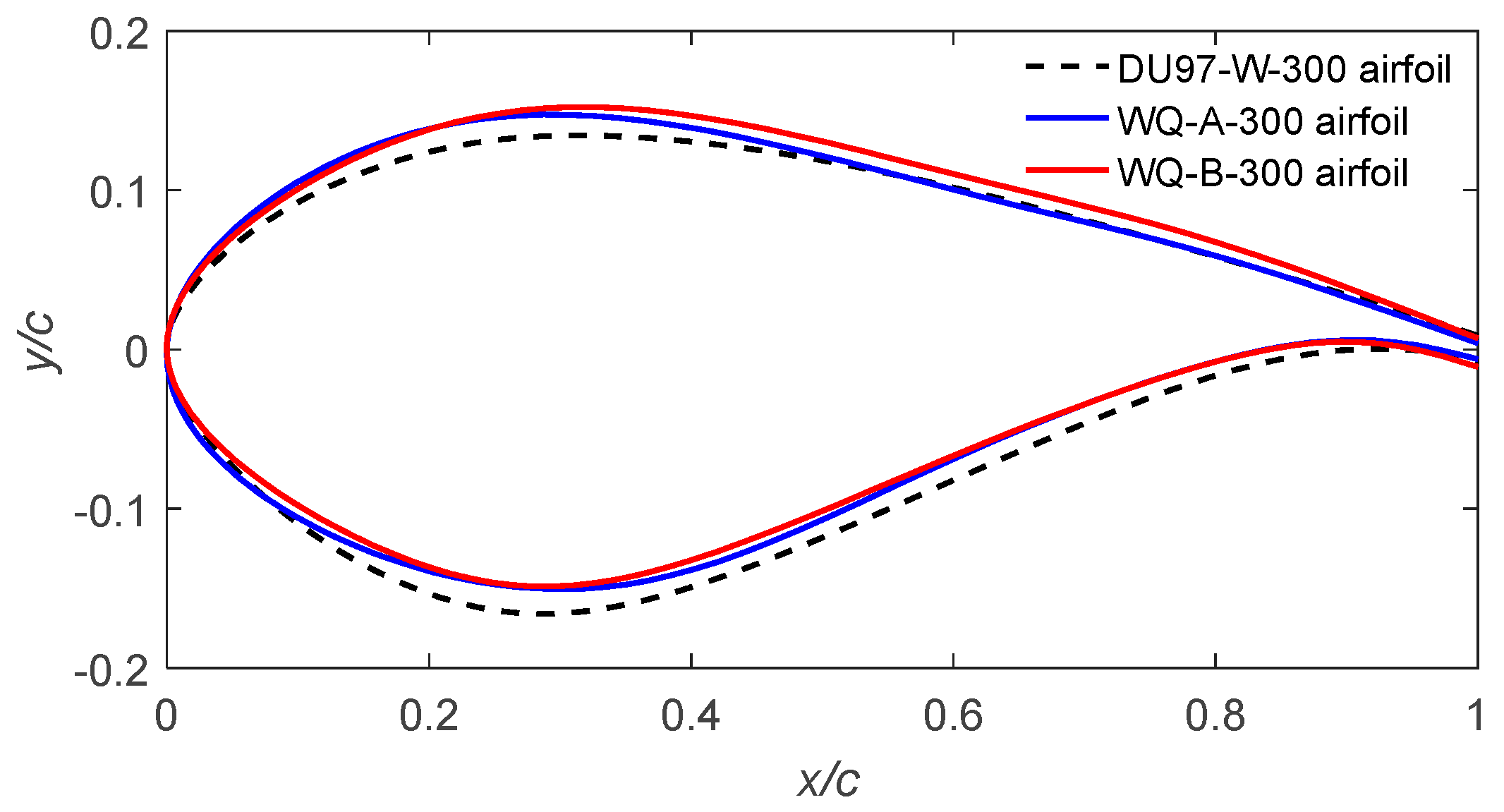
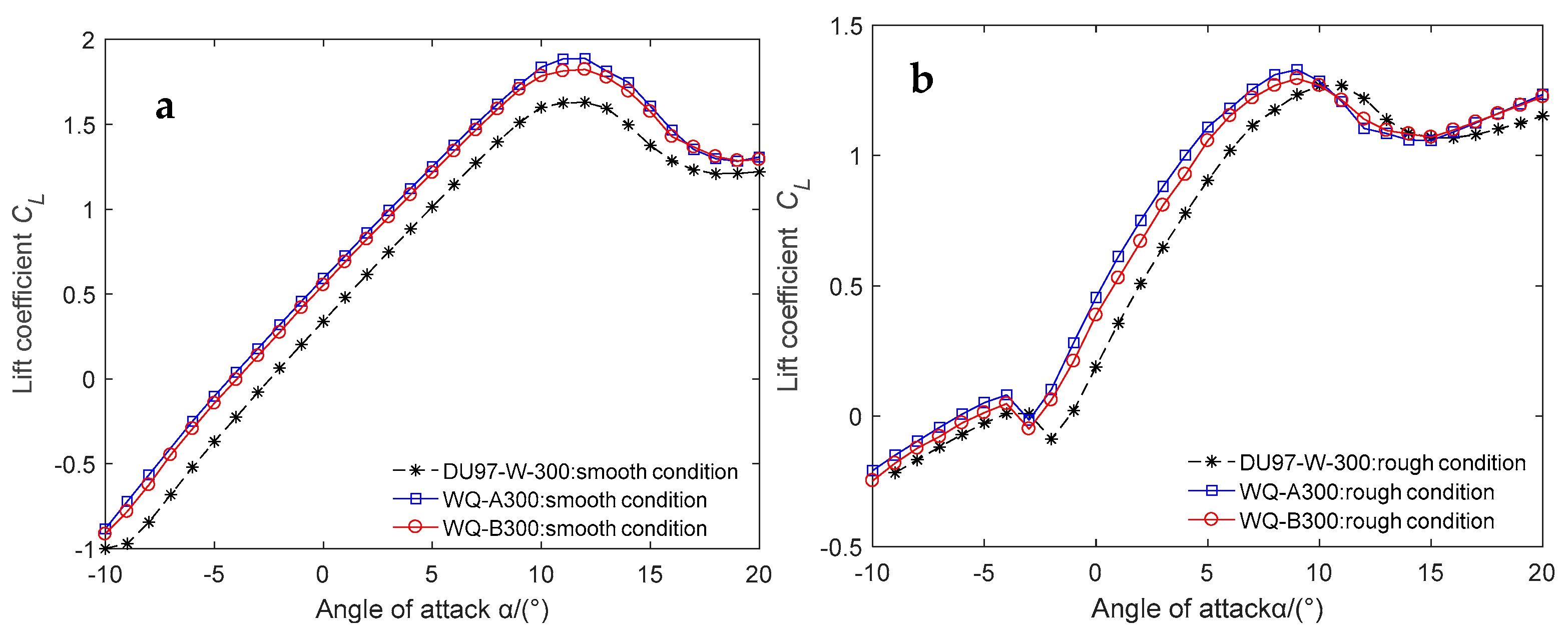
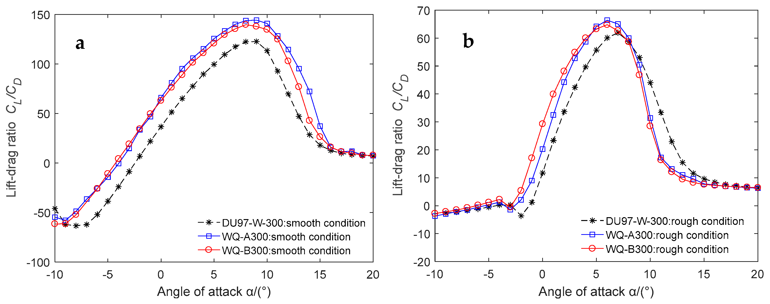
6. Optimal Results and Discussion
7. Conclusions
Author Contributions
Funding
Conflicts of Interest
References
- Tangle, J.L.; Somers, D.M. NREL Airfoil Families for HAWTs. In Proceedings of the WINDPOWER’95, Washington, DC, USA, 1 January 1995; pp. 117–123. [Google Scholar]
- Tangler, J.L.; Somers, D.M. Status of the Special Purpose Airfoil Famolies, SERI/CP-217-3315. In Proceedings of the WINDPOWER’87, San Fransisco, CA, USA, 5 October 1987; pp. 229–335. [Google Scholar]
- van Rooij, R.P.J.O.M.; Timmer, W.A. Roughness sensitivity considerations for thick rotor blade airfoils. J. Solar Energy Eng. 2003, 125, 468–478. [Google Scholar] [CrossRef]
- Timmer, W.A.; van Tooij, R.P.J.O.M. Summary of the Delft University wind turbine dedicated airfoils. J. Solar Energy Eng. 2003, 125, 488–496. [Google Scholar] [CrossRef]
- Fuglsong, P.; Bak, C. Development of the Risø Wind Turbine Airfoils. Wind Energy 2004, 7, 145–162. [Google Scholar] [CrossRef]
- Sobieczky, H. Parametric airfoils and wings. Notes Numer. Fluid Mech. 1998, 68, 71–88. [Google Scholar]
- Hajek, J. Parameterization of Airfoils and its Application in Aerodynamic Optimization. In Proceedings of the 16th Annual Conference of Doctoral Students—WDS 2007 Contributed Papers Part 1, Prague, Czech Republic, 5–8 June 2007; Matfyzpress: Prgtue, Czech Republic, 2007; pp. 233–240. [Google Scholar]
- Ava, S.; Alireza, J. Airfoil shape parameterization for optimum Navier-Stokes design with genetic algorithm. Aerosp. Sci. Technol. 2007, 11, 443–450. [Google Scholar]
- Chen, J.; Wang, Q.; Pang, X.P.; Li, S.L.; Guo, X.F. Improvement of Airfoil Design Using Smooth Curvature Technique. Renew. Energy 2013, 51, 426–435. [Google Scholar] [CrossRef]
- Chen, J.; Wang, Q.; Zhang, S.Q.; Peter, E.; Francesco, G. A new direct design method of wind turbine airfoils and wind tunnel experiment. Appl. Math. Model. 2016, 40, 2002–2014. [Google Scholar] [CrossRef]
- Seo, S.H.; Hong, C.H. Performance improvement of airfoils for wind blade with the groove. Int. J. Green Energy 2016, 13, 34–39. [Google Scholar] [CrossRef]
- Cheng, J.T.; Zhu, W.J.; Fischer, A.; Garcia, N.R.; Madsen, J.; Chen, J.; Shen, W.Z. Design and validation of the high performance and low noise CQU-DTU-LN1 airfoils. Wind Energy 2014, 17, 1817–1833. [Google Scholar] [CrossRef]
- Zhu, W.J.; Shen, W.Z.; Chen, J. Nørkær Sørensen. Integrated airfoil and blade design method for large wind turbines. Renew. Energy 2014, 70, 172–183. [Google Scholar] [CrossRef]
- Mortazavi, S.M.; Soltani, M.R.; Motieyan, H. A Pareto Optimal Multi-objective Optimization for a Horizontal Axis Wind Turbine Blade Airfoil Sections Utilizing Exergy Analysis and Neural Networks. J. Wind Eng. Ind. Aerodyn. 2015, 136, 62–72. [Google Scholar] [CrossRef]
- Li, X.X.; Yang, K.; Bai, J.Y.; Xu, J.Z. A new optimization approach to improve overall performance of thick wind turbine airfoils. Energy 2016, 116, 202–213. [Google Scholar] [CrossRef]
- Li, X.X.; Zhang, L.; Song, J.J.; Bian, F.J.; Yang, K. Airfoil design for large horizontal axis wind turbines in low wind speed regions. Renew. Energy 2020, 145, 2345–2357. [Google Scholar] [CrossRef]
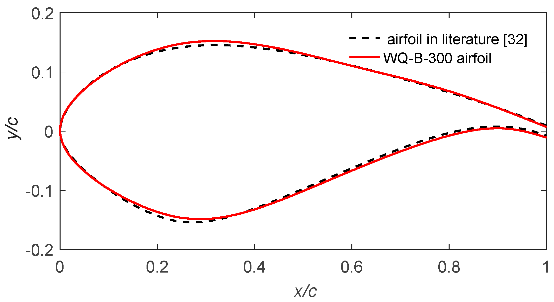
- Vecchia, P.D.; Daniele, E.; D’Amato, E. An airfoil shape optimization technique coupling Parsec parameterization and evolutionary algorithm. Aerosp. Sci. Technol. 2014, 32, 103–110. [Google Scholar] [CrossRef]
- Pereira, R.; Timmer, W.A.; de Oliveira, G.; van Bussel, G.J.W. Design of HAWT airfoils tailored for active flow control. Wind Energy 2017, 20, 1569–1583. [Google Scholar] [CrossRef]
- Miller, M.; Slew, K.L.; Matida, E. The development of a flat back wind turbine airfoil family. Wind Energy 2018, 21, 1372–1382. [Google Scholar] [CrossRef]
- Ram, K.R.; Lal, S.P.; Ahmed, M.R. Design and optimization of airfoils and a 20 kW wind turbine using multi-objective genetic algorithm and HARP_Opt code. Renew. Energy 2019, 144, 56–67. [Google Scholar] [CrossRef]
- Soemarwoto, B.I.; Labrujere, T.E. Airfoil design and optimization methods: Recent progress at NLR. Int. J. Numer. Methods Fluids 1999, 30, 217–228. [Google Scholar] [CrossRef]
- Larsen, J.W.; Nielsen, S.R.K.; Krenk, S. Dynamic stall model for wind turbine airfoils. J. Fluids Struct. 2007, 23, 959–982. [Google Scholar] [CrossRef]
- Baker, J.P.; Mayda, E.A.; van Dam, C.P. Experimental analysis of thick blunt trailing-edge wind turbine airfoils. J. Solar Energy Eng. 2006, 128, 422–431. [Google Scholar] [CrossRef]
- Bermudez, L.; Velazquez, A.; Matesanz, A. Viscous–inviscid method for the simulation of turbulent unsteady wind turbine airfoil flow. J. Wind Eng. Ind. Aerodyn. 2002, 90, 643–661. [Google Scholar] [CrossRef]
- Wang, X.D.; Chen, J.; Shen, W.Z.; Zhang, S.Q. Integration Study on Airfoil Profile for Wind Turbines. Chin. J. Constr. Mach. 2009, 20, 211–228. (In Chinese) [Google Scholar]
- Singh, R.K.; Ahmed, M.R. Design of a low Reynolds number airfoil for small horizontal axis wind turbines. Renew. Energy 2012, 42, 66–76. [Google Scholar] [CrossRef]
- Fuglsang, P.; Madsen, H.A. Optimization method for wind turbine rotors. J. Wind Eng. Ind. Aerodyn. 1999, 80, 191–206. [Google Scholar] [CrossRef]
- Abbott, I.H.; Von Doenhoff, A.E. Theory of Wing Sections; Dover Publications: New York, NY, USA, 1959. [Google Scholar]
- John, D.; Anderson, J. Fundamentals of Aerodynamics; McGraw-Hill Book Company: New York, NY, USA, 1985. [Google Scholar]
- Chen, H.; Yu, W.B.; Capellaro, M. A critical assessment of computer tools for calculating composite wind turbine blade properties. Wind Energy 2010, 13, 497–516. [Google Scholar] [CrossRef]
- Wang, L.; Liu, X.W.; Guo, L.G.; Renevier, N.; Stables, M. A mathematical model for calculating cross-sectional properties of modern wind turbine composite blades. Renew. Energy 2014, 64, 52–60. [Google Scholar] [CrossRef]
- Yang, H.; Chen, J.; Pang, X.P.; Chen, G. A new aero-structural optimization method for wind turbine blades used in low wind speed areas. Compos. Struct. 2019, 207, 446–459. [Google Scholar] [CrossRef]


| Num | Materials | E1 (GPa) | E2 (GPa) | G12 (GPa) | Poisson Ratio | Density (kg/m3) | Thickness (mm) |
|---|---|---|---|---|---|---|---|
| A | unidirectional | 39.18 | 11.69 | 3.5 | 0.3 | 1940 | 0.892 |
| B | bi-axial | 11.5 | 11.5 | 10.8 | 0.48 | 1970 | 0.555 |
| C | trial laminate | 25.8 | 13.59 | 7.36 | 0.36 | 1842 | 0.906 |
| D | coating | 3.44 | 3.44 | 1.38 | 0.3 | 1235 | 0.6 |
| E | PVC foam | 0.035 | 0.035 | 0.022 | 0.3 | 60 | 5 |
| Leading Reinforce | Leading Surface | Main Beam | Trailing Surface | Trailing Reinforce | Big Web | Small Web | |
|---|---|---|---|---|---|---|---|
| layer | D+2C+22A+2C+D | D+2C+22A+E+2C+D | D+2B+2C+55A+2C+2B+D | D+2C+22A+E+2C+D | D+2C+22A+2C+D | B+2E+B | B+E+B |
| Stiffness | Calculated Results | PreComp Results | Measured Data |
|---|---|---|---|
| EIx(N·m2) | 1.12 × 10⁹ | 1.21 × 10⁹ | 1.04 × 10⁹ |
| EIy(N·m2) | 3.57 × 10⁸ | 3.64 × 10⁸ | 3.28 × 10⁸ |
| Airfoil Name | Smooth Condition | Rough Condition | ||
|---|---|---|---|---|
| CL,max | L/D,max | CL,max | L/D,max | |
| DU97-W-300 | 1.631 | 122.638 | 1.268 | 61.889 |
| (12°) | (9°) | (11°) | (7°) | |
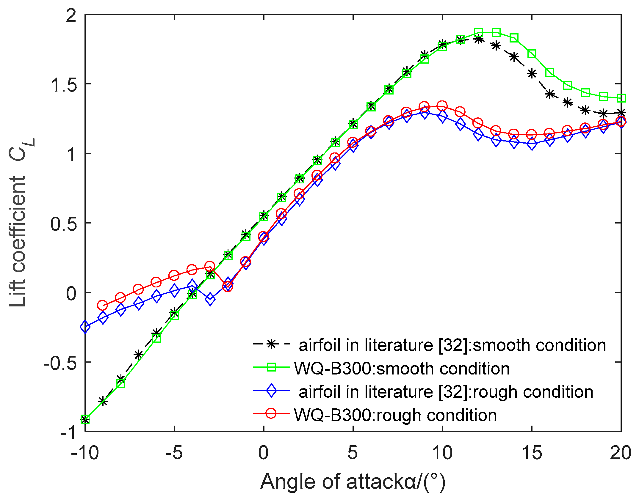
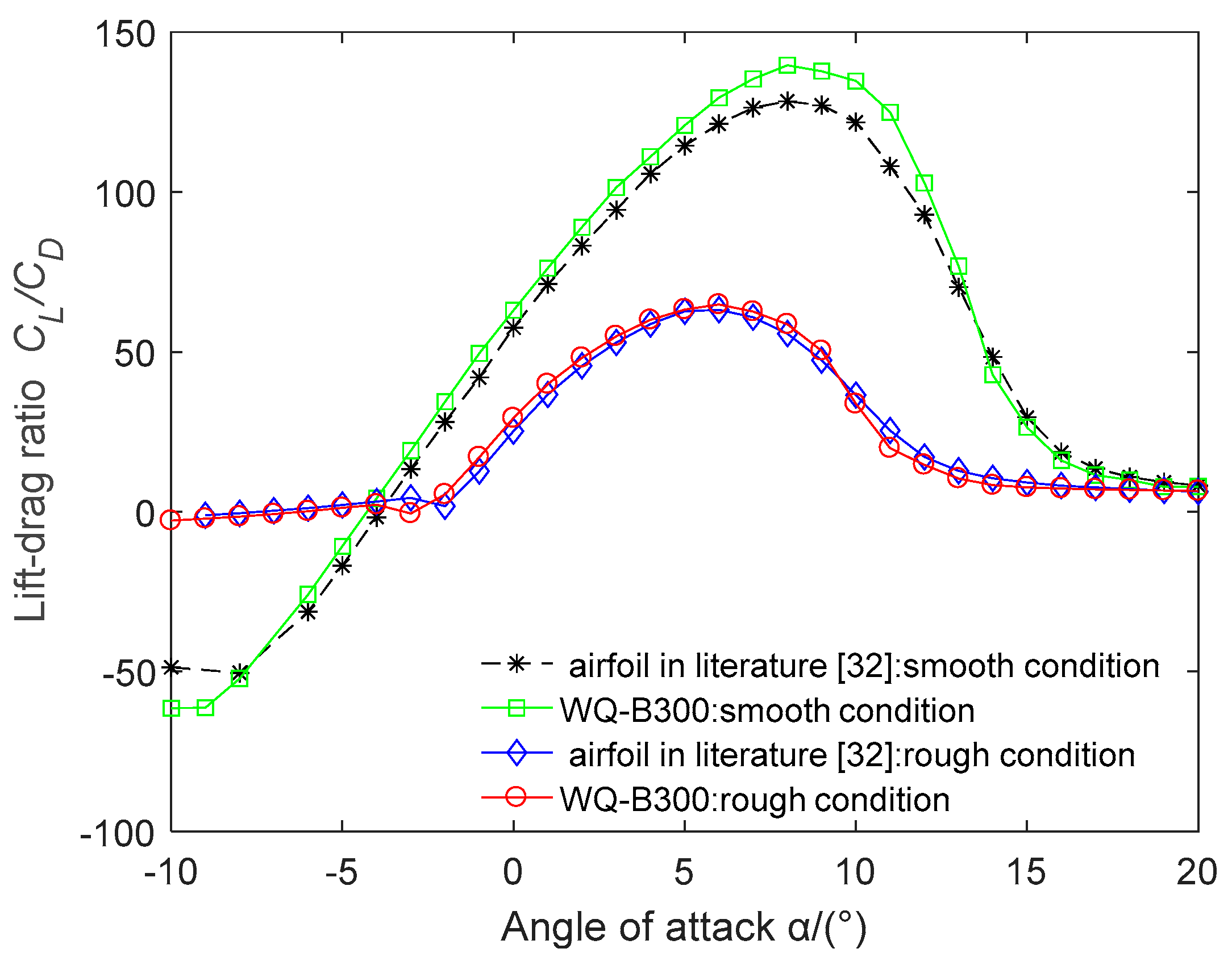
| Reference [32] airfoil | 1.801 | 128.449 | 1.292 | 63.176 |
| (12°) | (8°) | (9°) | (6°) | |
| WQ-A300 | 1.889 | 141.756 | 1.326 | 66.391 |
| (14°) | (9°) | (10°) | (6°) | |
| WQ-B300 | 1.823 | 139.647 | 1.295 | 64.798 |
| (12°) | (8°) | (9°) | (6°) | |
| Layer Parameters | DU97-W-300 Section | WQ-B300 Section |
|---|---|---|
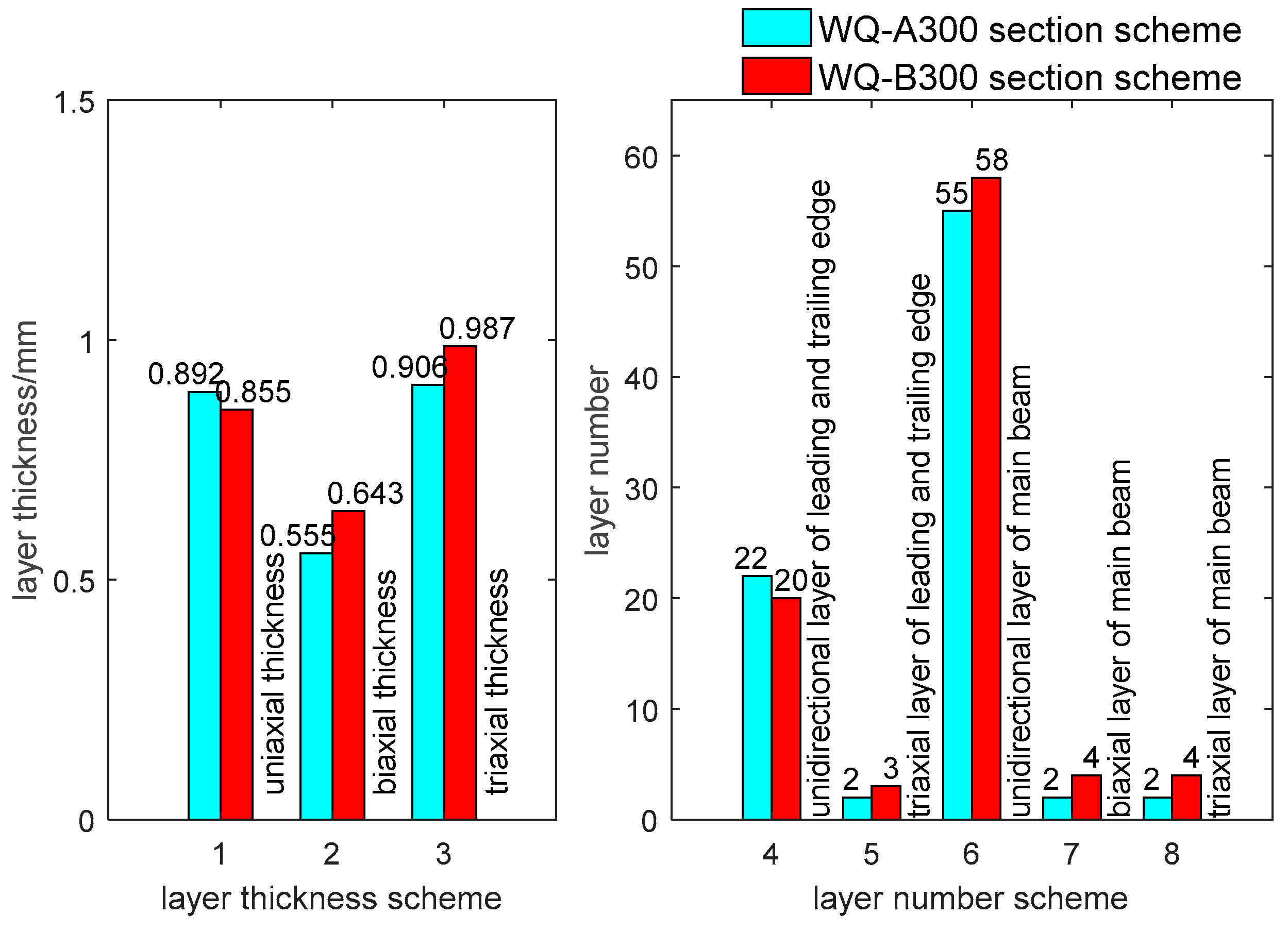
| Uniaxial thickness (mm) | 0.892 | 0.855 |
| Biaxial thickness (mm) | 0.555 | 0.643 |
| Triaxial thickness (mm) | 0.906 | 0.987 |
| Uniaxial layer of leading and trailing edge | 22 | 20 |
| Triaxial layer of leading and trailing edge | 2 | 3 |
| Uniaxial layer of main beam | 55 | 58 |
| biaxial layer of main beam | 2 | 4 |
| triaxial layer of main beam | 2 | 4 |
| Main beam position | 0.20 C 0.55 C | 0.185 C 0.522 C |
| Stiffness | DU97-W-300 Section | WQ-A300 Section | WQ-B300 Section |
|---|---|---|---|
| Flapwise EIx (N·m2) | 1.12 × 10⁹ | 1.13 × 10⁹ | 1.19 × 10⁹ |
| Edgewise EIy (N·m2) | 3.57 × 10⁸ | 3.48 × 10⁸ | 3.87 × 10⁸ |
© 2019 by the authors. Licensee MDPI, Basel, Switzerland. This article is an open access article distributed under the terms and conditions of the Creative Commons Attribution (CC BY) license (http://creativecommons.org/licenses/by/4.0/).
Share and Cite
Wang, Q.; Huang, P.; Gan, D.; Wang, J. Integrated Design of Aerodynamic Performance and Structural Characteristics for Medium Thickness Wind Turbine Airfoil. Appl. Sci. 2019, 9, 5243. https://doi.org/10.3390/app9235243
Wang Q, Huang P, Gan D, Wang J. Integrated Design of Aerodynamic Performance and Structural Characteristics for Medium Thickness Wind Turbine Airfoil. Applied Sciences. 2019; 9(23):5243. https://doi.org/10.3390/app9235243
Chicago/Turabian StyleWang, Quan, Pan Huang, Di Gan, and Jun Wang. 2019. "Integrated Design of Aerodynamic Performance and Structural Characteristics for Medium Thickness Wind Turbine Airfoil" Applied Sciences 9, no. 23: 5243. https://doi.org/10.3390/app9235243
APA StyleWang, Q., Huang, P., Gan, D., & Wang, J. (2019). Integrated Design of Aerodynamic Performance and Structural Characteristics for Medium Thickness Wind Turbine Airfoil. Applied Sciences, 9(23), 5243. https://doi.org/10.3390/app9235243