Article

Numerical Simulation of the Tip Leakage Vortex Characteristics in a Semi-Open Centrifugal Pump

1
Institute of Water Resources and Hydropower, Xi’an University of Technology, Xi’an 710048, China
2
State Key Laboratory Base of Eco-hydraulic Engineering in Arid Area, Xi’an University of Technology, Xi’an 710048, China
*
Author to whom correspondence should be addressed.
Appl. Sci. 2019, 9(23), 5244; https://doi.org/10.3390/app9235244
Submission received: 23 October 2019 / Revised: 27 November 2019 / Accepted: 29 November 2019 / Published: 2 December 2019
(This article belongs to the Section Energy Science and Technology)

Abstract

:
Tip leakage vortex has an important influence on the performance of semi-open centrifugal pumps. Simulations based on the three-dimensional Reynolds-Averaged Navier–Stokes were conducted to study the structural characteristics of tip leakage vortex and its effects on the internal flow field, and the Shear Stress Transport k-ω turbulence model was used to simulate the whole flow passage of centrifugal pumps with tip clearances of 0 mm and 1 mm. Then, the tip leakage vortex was analyzed using the relative vorticity transport equation. The numerical data and experimental results agreed well. The leakage vortex formed in the tip clearance led to 18.7% and 14.4% decrease in head and efficiency under design condition, respectively, and the bigger the flow rate, the fast the performance decreased. Tip leakage vortex formed at the leading edge of the blade moved along the suction surface. Whereas the tip leakage vortex formed near the middle of the blade extended to the pressure surface of the adjacent blade. This phenomenon deteriorated the flow field and induced passage vortex, thereby reducing the static pressure and blade load and changing the static pressure distribution law. The formation and development of leakage vortex could be attributed to the relative vortex stretching the term. The Coriolis force term could reflect the change of vorticity caused by leakage flow, and the viscous diffusion term served as the vorticity source.

1. Introduction

Semi-open centrifugal pumps are generally applied in various fields, such as national defense, aerospace, and civil industry, due to their convenient maintenance, long operation time, and high efficiency [1]. However, because of the existence of tip clearance, the tip leakage flow or even tip leakage vortex is formed near the tip clearance under the pressure gradient action of the blade pressure surface and suction surface. As a result, the performance of centrifugal pumps declines, and the vibration and noise increase. This phenomenon is evident in medium and low specific-speed centrifugal pumps [2,3,4].
In recent years, many scholars have discussed the effect of clearance near the tip region on the external characteristics of fluid machinery. The conclusions show that the flow structure has a considerable effect on the internal flow field [5,6,7]. Kaneko et al. [8] and Robert et al. [9] found by numerical simulation that the tip clearance could substantially change the internal flow pattern of the centrifugal impeller, which reduced the performance of the compressor and it was more obvious with large tip clearance. This conclusion was verified by the experiment [10]. Jia et al. [11] and Gao et al. [12] discovered that the compressor performance without tip clearance was not necessarily better than it with clearance. A suitable small gap could achieve higher efficiency than no gap. This finding suggested that an optimal clearance could minimize the flow loss in the impeller. Liu et al. [13] studied a mixed-flow pump through numerical simulation and determined the following: (1) the head and efficiency were considerably affected by the shape and parameters of tip clearance, and (2) the reduction of efficiency was almost linear with the change of tip clearance under design conditions. Bing et al. [14] and Zhang et al. [15] obtained the same findings and further determined that the slope increased with flow rate. Jia et al. [16] investigated a low-specific speed of the semi-open centrifugal pump and discovered that external characteristics substantially decreased with the increase of tip clearance height, but the hump phenomenon in small flow conditions weakened. Farid et al. [17] studied three different centrifugal pump gaps (1, 2, and 3 mm) and found that the tip clearance and external characteristics exhibited a regression effect, and the decline in small flow rate conditions was considerably less than that in the large flow rate conditions. The influence of the tip clearance on the external characteristics is generally complicated and related to the type of fluid machinery and operation conditions.
Operational stability is an important parameter to judge mechanical performance. Numbers of studies have shown that pressure pulsation, axial force, radial force, and unsteady vortex structure are critical to operational stability [18,19,20,21]. The internal flow field of the semi-open impeller becomes unstable, and the flow mechanism is complicated due to the influence of the tip leakage flow. Gao [22] studied the blade wake of a centrifugal compressor with different tip clearances and discovered that the tip leakage vortex intensity increased with tip clearance size. The low-speed region near the shroud simultaneously expanded and moved to the suction surface of the blade. The tip leakage vortex mixed with the blade outlet wake and the loss in the passage and vibration increased. Li [23] studied a mixed-flow pump under small flow rate conditions and found that the leakage in the tip region gradually increased with the tip clearance. In addition, the mixing effect between the tip leakage flow and the main flow of the impeller increased, which caused the blocking effect of the main flow in the passage. The secondary flow and the vortex, as well as other flow instability phenomena, also appeared. The tip clearance could induce the early occurrence of cavitation and increase the pressure fluctuation amplitude [24]. The tip leakage vortex could facilitate the possible occurrence of flow separation and vortex, especially in small flow rate conditions. The rotating stall could occur in advance [25]. Lu [26] studied the semi-open centrifugal pump and discovered that the angle between the leakage vortex core and the camber line periodically changed with the tip blade loading. The leakage flow accelerated the flow separation at the tip, forming a vortex tube that extends from the tip blade surface to the shroud, and the low-frequency pressure fluctuation was developed.
In summary, studies on the tip clearance of semi-open centrifugal pumps are relatively few, especially the lack of in-depth investigations on the tip leakage vortex structure. In this paper, the numerical simulation of the semi-open centrifugal pump was performed to study the influence law of the tip clearance on the internal flow field. The relative vorticity transport equation was used to analyze the characteristics of the tip leakage vortex, and the formation and development mechanism of the leakage vortex structure was revealed.

2. Computational Model and Method

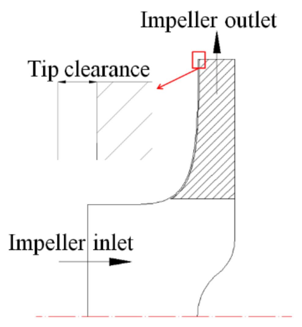
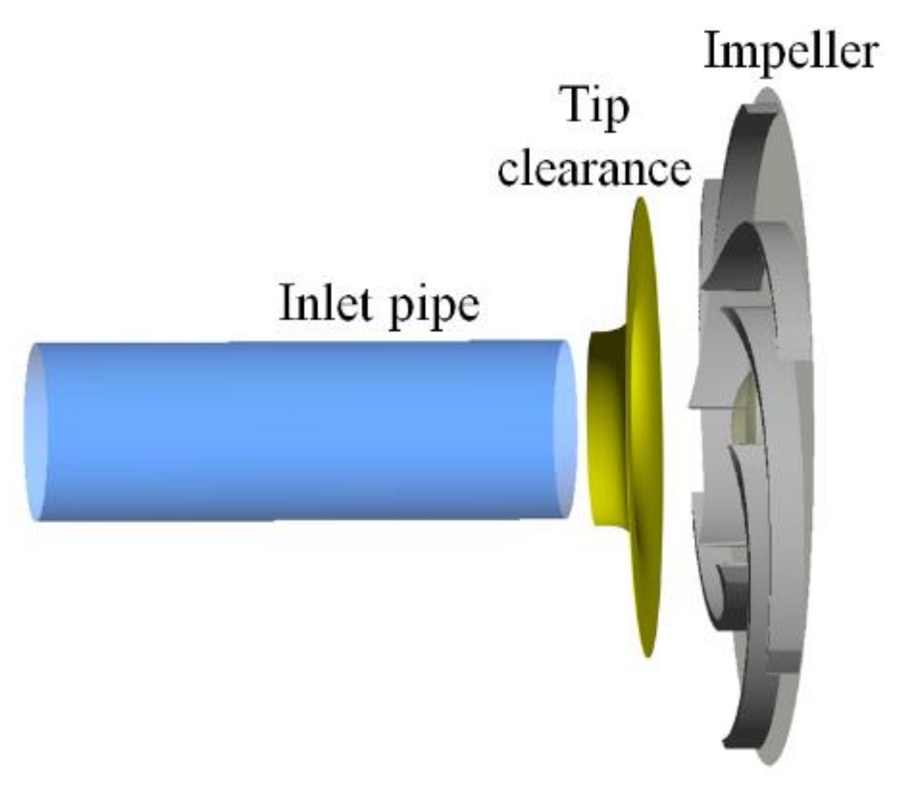
2.1. Physical Model of the Pump
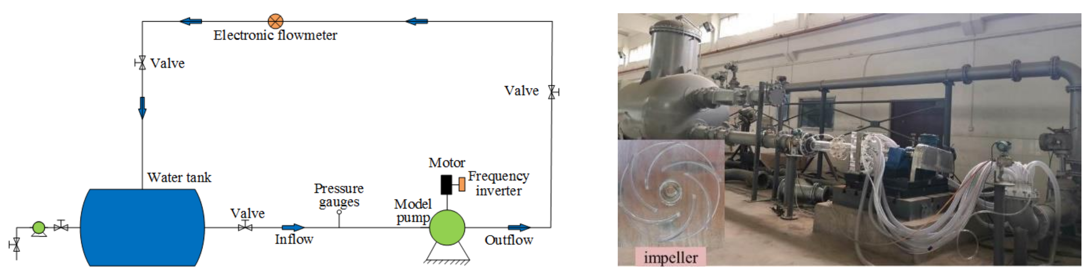
A semi-open centrifugal pump, with a low-specific speed ns = 94.97, was designed for investigation. The main components of this pump include an inlet pipe, impeller, and vaneless diffuser, as shown in Figure 1. This impeller was designed based on a single arc technique and two-dimensional blades. The sketch map of the tip clearance is shown in Figure 2. In the impeller with the tip clearance (TC), the height of the tip clearance was 1 mm from the leading to the trailing edge of the blade, whereas the impeller without the tip clearance (NTC) had a similar configuration to that of TC, but the shroud was directly connected with the blade. The designed parameters of the pump head, flow rate, and speed were 7 m, 47 m3/h, and 980 r/min, respectively. The detailed geometrical parameters are presented in Table 1.

2.2. Test Rig

As shown in Figure 3, experimental measurements were conducted on a closed test rig for a centrifugal pump in the State Key Laboratory of Eco-hydraulics in the Northwest Arid Region, Xi’an University of Technology. The comprehensive measurement errors of the head and efficiency were ±1.41% and ±1.57%, respectively. The flow rate could be measured using the electromagnetic flowmeter with an accuracy lower than 1%. A frequency inverter manufactured by Asea Brown Boveri Ltd. was used to regulate the rotating speed and ensure that the pump operating at the nominal rotating speed of 980 r/min. The fluctuation of rotating speed at different flow rates was approximately 3 r/min, indicating that the uncertainty of the speed was less than 0.31%.

2.3. Numerical Method

In this study, ANSYS CFX software was used for the numerical simulation. The internal flow field information was obtained by solving the continuity equation and the momentum equation of incompressible fluid. So, the turbulence model was a key issue. The Shear Stress Transport (SST) k-ω two-equation turbulence model, which combines the standard k-ε and k-ω model, was designed to produce highly accurate predictions of flow separation phenomenon under the adverse pressure gradient, which was also applicable to the numerical description of the tip leakage flow. The closure mode of the SST k-ω was expressed as,
( ρ k ) t + x j ρ u j k = x j μ + μ t σ k k x j + P k β * ρ k ω
( ρ ω ) t + x j ρ u j ω = x j μ + μ t σ ω 3 ω x j + α 3 ω k P k β ρ k ω + 1 F 1 2 ρ 1 σ ω 2 ω k x j ω x j
μ t = ρ α 1 k max α 1 ω , S F 2
F 1 = tanh arg 1 4
arg 1 = min max k β ω y , 500 ν y 2 ω , 4 ρ k C D k w σ ω 2 y 2
F 2 = tanh arg 2 2
arg 2 = max 2 k β ω y , 500 ν y 2 ω
where k and ω, respectively, represent the turbulence kinetic energy and turbulence eddy frequency; Ρ and ρ are the pressure and density; F1 and F2 represent the blending function; Pk is the turbulence production due to viscous forces; and α1, α3, β*, β’, σk, σω2, and σω3 are the model constants.
The total pressure was used and set to 101,325 Pa at the inlet. The discharge at the vaneless diffuser was set for the outlet boundary condition. In addition, no-slip wall condition in the solid walls was also specified. The frozen rotor was used as the interface between the rotating and fixed domain. Water at normal temperature was used as a working fluid.

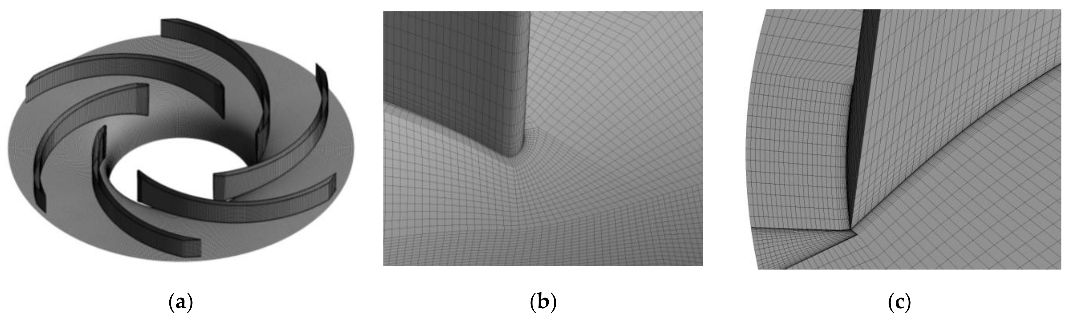
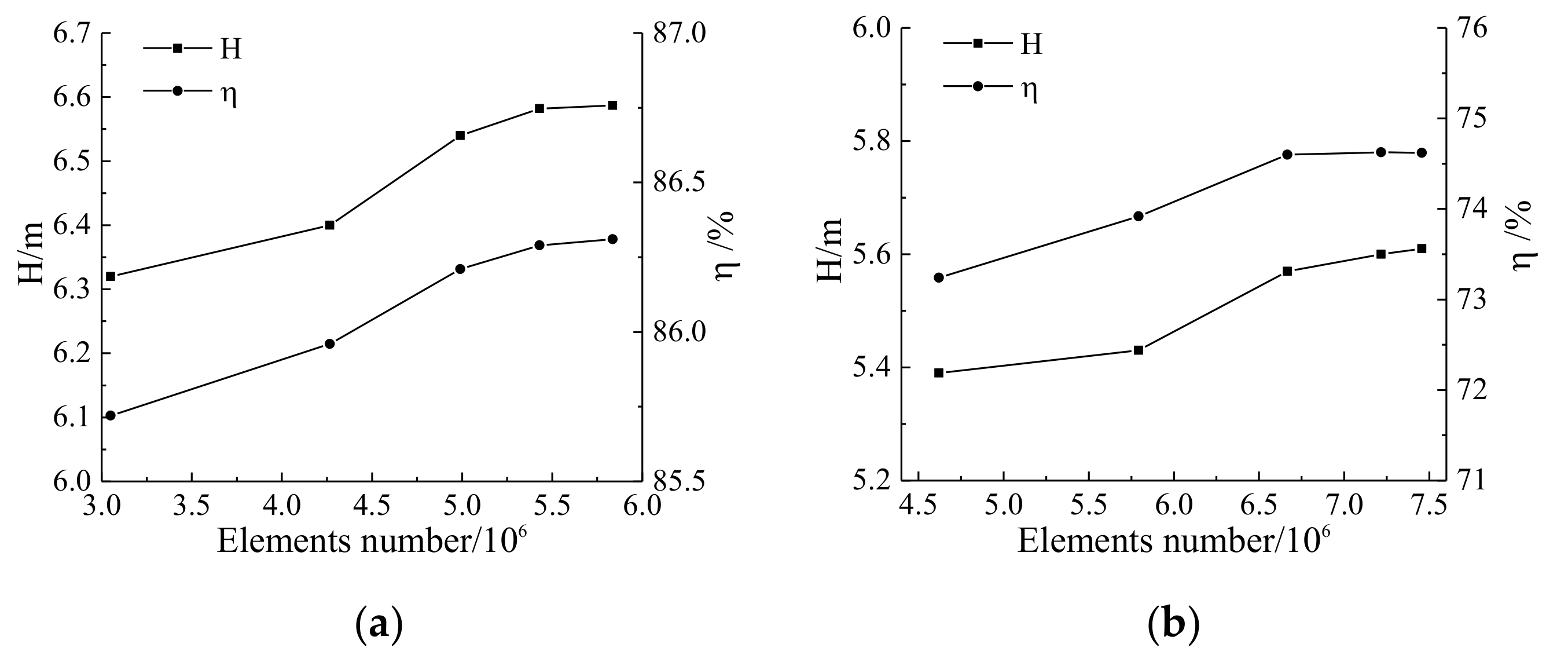
2.4. Grid Production

The quality of the mesh directly determines the accuracy and reliability of the numerical simulation results. In this study, the hexahedral structured grids were employed for all computational domains. The local grid in the tip clearance region had also been refined to ensure the accuracy of the tip clearance flow. Five densities of meshes with different elements were generated for the analysis of mesh sensitivity. Figure 4 shows the calculated head and efficiency under the design condition. The head and efficiency slightly changed when the number of grids with and without tip clearance was more than 6.66 and 5.42 million, respectively. Considering the numerical accuracy and the cost of computational resources, the fourth set of mesh was utilized in the following simulations. The mesh of the impeller is shown in Figure 5, and the number of grids of each component is shown in Table 2.

3. Results and Discussions

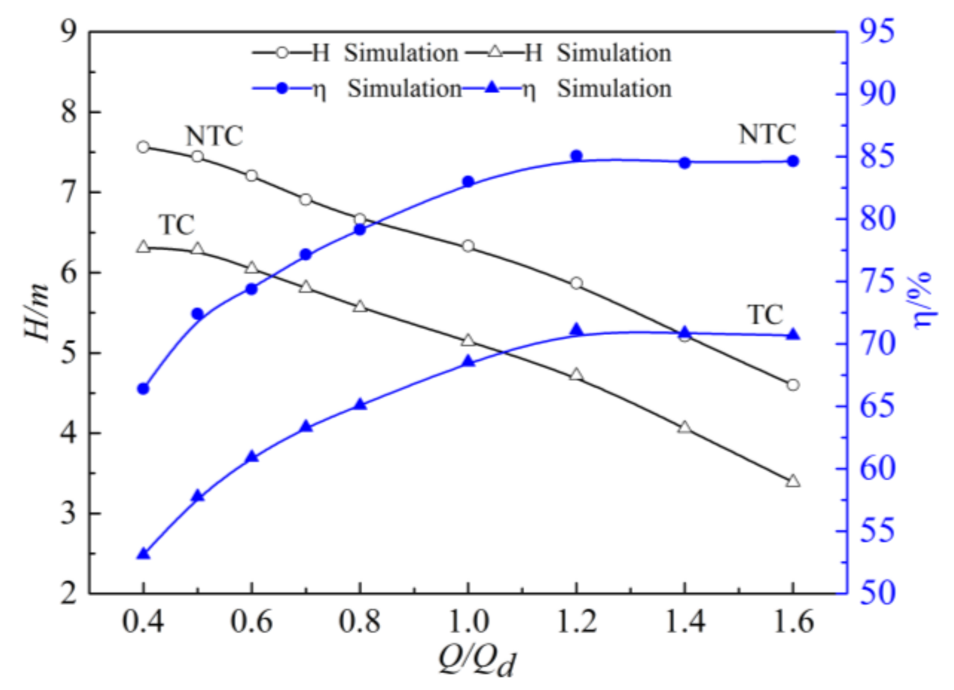
3.1. Numerical Results Validation

The comparison between experimental data and numerical results with the 1.0 mm tip clearance was conducted, as shown in Figure 6, to verify the accuracy of the numerical simulation method in this study. A good agreement between the numerical and the experiment results was obtained. The maximum and minimum relative errors of the head between experimental data and numerical results were 5.6% at 1.2 Qd and 0.3% at 0.4 Qd. Under the design condition, the relative errors of head and efficiency were 4.2% and 4.0%. Consequently, the grids and numerical methods were verified to guarantee the accuracy and reliability of results and the internal flow field.
The head and efficiency of the centrifugal pump with and without tip clearance are shown in Figure 7. Regardless of the presence of tip clearance, the changing trend of the external characteristic curve was the same. However, the formation of leakage vortex in the tip clearance led to a considerable decrease in head and efficiency, which, respectively, decreased by 18.7% and 14.4% under the design condition. The decline became increasingly serious with the flow rate. The design condition was selected for a detailed analysis.

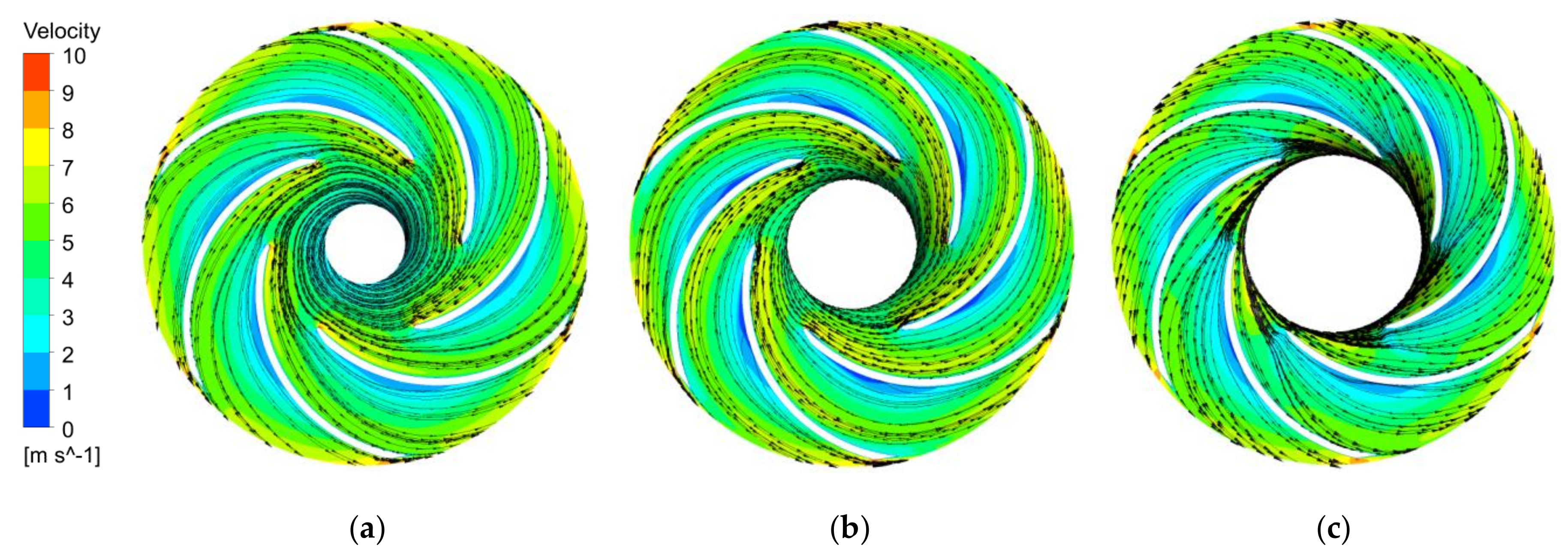
3.2. Internal Flow Field

The streamline distributions of different blade spans are shown in Figure 8 and Figure 9. When the span was 0.05 and 0.5, the velocity of TC was larger than that of NTC, and the low-speed region on the blade pressure surface was improved. However, the streamline was disturbed near the impeller outlet. When the span was 0.95, the flow field of NTC was relatively smooth. But a low-speed region was observed at the blade leading edge of TC, and it gathered in the middle of the passage that led to a blockage in the flow when it moved to downstream along the pressure surface because the plane near the tip clearance was considerably affected by the leakage vortex.
The flow at the blade inlet was analyzed to explore the reasons for the above phenomena. Figure 10 presents the distribution of the relative flow angle along the circumferential direction of different spans at the blade inlet. The relative flow angle distribution showed evident periodicity when the span was equal to 0.05 and 0.5. The number of periods was equal to the number of blades. From the suction surface to the pressure surface of the adjacent blade, the relative flow angle increased first and then decreased. The maximum was obtained in the circumferential middle position of two blades. Compared with NTC, the relative flow angle of TC increased considerably, but the fluctuation range decreased, and the distribution law remained the same. The large inflow angle resulted in the improvement of the low-speed region of the blade pressure surface. When the span was 0.95, the relative flow angle considerably increased, and the distribution law evidently changed because closeness to the tip region remarkably influenced the tip clearance.
From the suction surface to the pressure surface, the relative flow angle increased first and then decreased to 68° in the circumferential middle position. Afterward, the relative flow angle increased again and then finally decreased to 15°. Two maxima close to 90° and a minimum value close to 68° appeared in one flow passage. The change in relative flow angle distribution led to a large negative attack angle that appeared at the blade inlet. So, the flow separation occurred on the pressure surface of the blade, and the low-speed region was formed that blocked the flow passage.
The pressure distribution on the blade surface could accurately reflect the turbocharging performance of the pump and was significantly affected by the structure of leakage vortex. The static pressure coefficient Cp, which is expressed, as shown in the equation below, was introduced to illustrate the static pressure distribution law on the blade surface.
C p = P P ¯ 0.5 ρ V i n 2
where P is the static pressure on the blade, Vin and P ¯ are the velocity and the static pressure of the inlet, respectively, and ρ stands for the fluid density.
The Cp distribution on the blade surface is shown in Figure 11. “M” indicates the meridional distance from the leading edge to the trailing edge of the blade; “0% M” and “100% M” are the leading edge and trailing edge, respectively. The Cp of the blade without tip clearance smoothly increases with the meridional distance, but the intersection points appear near the trailing edge of the blade. The Cp of the pressure surface is smaller than that of the suction surface due to the wake vortex at the trailing edge of the blade.
The tip clearance had a considerable effect on the distribution of Cp at any span of the blade. When the span was equal to 0.05, the impact of the tip clearance on the Cp of the suction surface and pressure surface was small, demonstrating approximately 0–30% M and 30–50% M, respectively. However, a considerable decline was observed in other positions. The Cp of pressure surface was almost equal to that of the suction surface at 10% M. The distribution law of the 0.5 span was similar to that of 0.05 span, while the tip clearance led to the decrease of Cp on all pressure surface, and the declining amplitude increased remarkably. When the span was equal to 0.95, the declining amplitude of the Cp on the pressure surface was considerably larger than that on the suction surface, which resulted in a decrease in ΔCp and blade load. The pressure surface Cp almost coincided with that of the suction surface at 0–10% M, while the distribution demonstrated unstable fluctuation at 10–40% M. The tip leakage vortex generated by the pressure difference generally had a greater influence near the leading edge than that at the trailing edge of the blade under the design condition. The static pressure coefficient of the blade surface was reduced, and the distribution law near the leading edge was changed because of the influence of leakage vortex on the flow field.

3.3. Structure of the Tip Leakage Vortex

The standard helicity Hn [27,28] is defined as shown below to quantitatively identify the vortex structure.
H n = Ω W Ω W
where Ω and Ω , respectively, denote the vector and modulus of relative vorticity. W and W , respectively, denote the vector and module of relative velocity.
Hn essentially represents the cosine value of the angle between the relative velocity vectors and vorticity vectors. Hn is equal to 1, −1, and 0 when the direction of the vorticity vector and relative velocity vector is the same, opposite, and orthogonal, respectively. Moreover, the Hn value of 1 or −1 represents the vortex core, which is characterized by strong vortex roll-up.
The Q criterion can accurately characterize the structure of vortices. Therefore, this criterion is widely used in rotating machinery [29,30,31,32,33]. Q, which is also regarded as the vortex core, is the region where the rotation rate tensor exceeds the strain rate tensor. The vortex exists when Q > 0, and large Q signifies a strong vortex intensity.
Q = 1 2 ( Ω Ω S S )
where Ω and S denote the vector of relative vorticity and strain rate tensor, respectively.
In the present work, the tip leakage vortex was characterized by the Q criterion. Figure 12 shows the isosurface distribution when Q = 1.0 × 10⁵ s−2. The structure of the tip leakage vortex in the impeller mainly comprised tip leakage vortex A (TLV A), B (TLV B), and a passage vortex. Moreover, the tip leakage flow was observed near the trailing edge of the blade. The Hn of TLV A was close to 1, which indicated the formation of tip leakage vortex core, and the direction of the vortex vector was the same as that of relative velocity. By contrast, the TLV B had varying Hn from −1 to 1, which indicated the complexity of the vortex structure. The formation of the tip leakage vortex was accompanied by the breakdown of the vortex. The tip leakage vortex would also deteriorate the flow field. Therefore, the passage vortex was generated downstream of the tip leakage vortex.
Figure 13 shows the streamline released from tip clearance for a detailed study of the tip leakage vortex structure. The red, black, and blue streamlines indicate release from 0–20% M, 30–50% M, and 75–85% M, respectively. All the streamlines were driven by the pressure gradient. TLV A formed at the leading edge of the blade, moved along the leakage core, and then broke at approximately 35% M. After mixing with the mainstream, TLV A flew downstream along the suction surface of the blade. Meanwhile, TLV B was formed near the middle of the blade. It moved to the leading edge of the pressure surface of adjacent blade B2. Most of the fluid was blocked by the wall. This condition changed the flow direction and made the fluid move in the opposite direction, and then TLV B broke at approximately 60% M. The broken fluid of TLV A and TLV B mixed and flew downstream along the suction surface of the blade. In addition, a small part of the fluid flows around the inlet of the adjacent blade B2 and moved along the suction surface of B2. The disturbance occurred in the adjacent flow passage. The flow was mainly the tip leakage flow rather than tip leakage vortex near the trailing edge of the blade. Under the action of pressure difference, the tip leakage flow moved circumferentially in the direction opposite to the impeller rotation. The entrainment effect was formed between the tip leakage flow and mainstream in the middle position of the B1 and B2, and the secondary leakage flow was formed at the trailing edge of B2.
The flow field would be seriously affected by the unstable tip leakage vortex, whereas the tip leakage flow was relatively stable. Therefore, the static pressure distribution showed unstable fluctuation at 0–50% M, while that at 0–50%, M increased smoothly, as shown in Figure 10c.

3.4. Vortex Analysis of Tip Leakage Vortex

The relative vorticity transport equation was used to analyze the initiation, development, and dissipation of the tip leakage vortex in the present study, which facilitated further analysis to receive a comprehensive understanding of the motion mechanism of vortices [34,35,36]. The equation is shown as,
D Ω D t = Ω W Ω W 2 × ω × W + ρ × p ρ 2 + ν 2 Ω
where ω and ν denote the rotating angular velocity and effective kinematic viscosity, respectively.
The left term indicates the variation ratio of vorticity, and there are four terms on the right hand. The first term is the relative vortex stretching term (RVS), which is related to the velocity gradient. The second term is the relative vorticity dilation term, which reflects the change in vorticity due to fluid compressibility. The third term is the Coriolis force term (CORF), which is related to the rotary movement. The fourth term is the baroclinic torque term, which represents the effect of pressure gradient and density gradient on vorticity. The last term is the viscous diffusion term (VISD), which is caused by the viscosity of the fluid. The water used as a working fluid is considered incompressible, so the second term and fourth terms could be ignored [37]. Six circumferential sections corresponding to spans 0.7, 0.8, 0.9, 0.95, 0.97, and 0.99 were set up to study the aforementioned term distribution rules under the designed flow rate and comprehensively get the flow field around the tip clearance region.
Figure 14 shows the RVS distribution. When the span was 0.95 and 0.97, the high RVS region began at the leading edge and moved downstream to 50% M along the suction surface. At 40% M, this region developed and extended to the leading edge of the adjacent blade with zonal distribution in the flow passage. The high RVS region coincided with the distribution of core and breakdown region of TLV A and TLV B by comparisons of Figure 11 and Figure 12. This finding indicated that high RVS was the main reason for the formation and development of tip leakage vortex. RVS decreased with the span; therefore, the tip leakage vortex gradually dissipated during the movement along the blade span direction. The stretching and bending of the leakage vortex during the movement was the main reason for the vorticity change.
Figure 15 demonstrates the distribution of CORF. The CORF of the tip region at the suction surface of the blade was found to be the largest among all span planes. CORF considerably decreased and exhibited ladder-like distribution as the span decreased from 0.99 to 0.7. The Coriolis force was generated by the rotation of the impeller, which induced the pressure gradient on the pressure surface and suction surface. The tip leakage flow was formed under the action of the pressure difference. Therefore, CORF was an important factor in driving the tip leakage flow. Furthermore, CORF could reflect changes in vorticity caused by tip leakage flow.
The distribution of VISD is presented in Figure 16. The micro-jet was formed in the tip clearance region under the action of the pressure difference between the blade pressure surface and suction surface. The motion direction of the micro-jet was opposite to that of the blade rotation. Therefore, the relative motion with different velocities was formed between micro-jet and rotating impeller and fixed shroud. The relative motion generated vorticity on the wall, and VISD became a vorticity source. When the span was 0.99, high VISD almost occupied the entire blade passage. When the spans were 0.97, 0.95, and 0.9, the high VISD region was mainly distributed on the suction surface of the blade. The high VISD region and value evidently decreased with the blade span. For the span of 0.8 and 0.7, VISD in most regions was small, which indicated that the effect was weak when the VISD vorticity source diffused to these sections.

4. Conclusions

In this paper, the numerical simulation of a semi-open centrifugal pump was conducted to investigate the characteristics and the initiation, development, and dissipation mechanism of the tip leakage vortex in the tip clearance region. Some findings are summarized as follows.
(1)
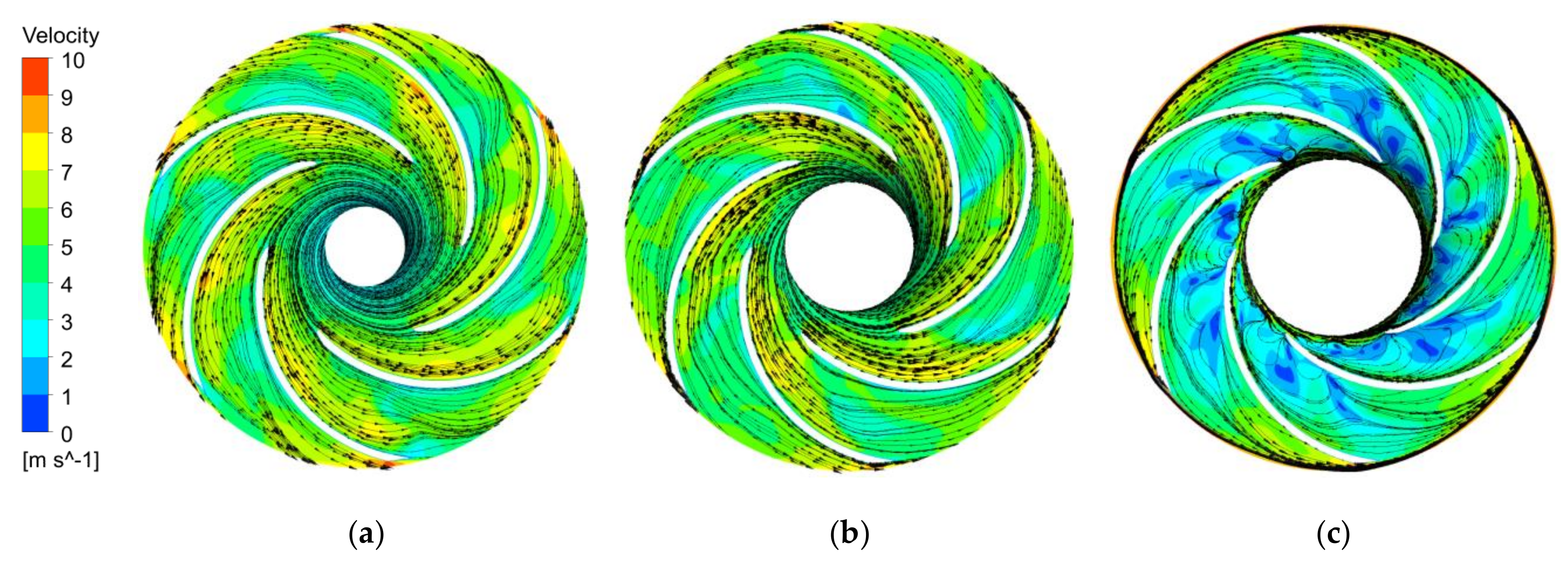
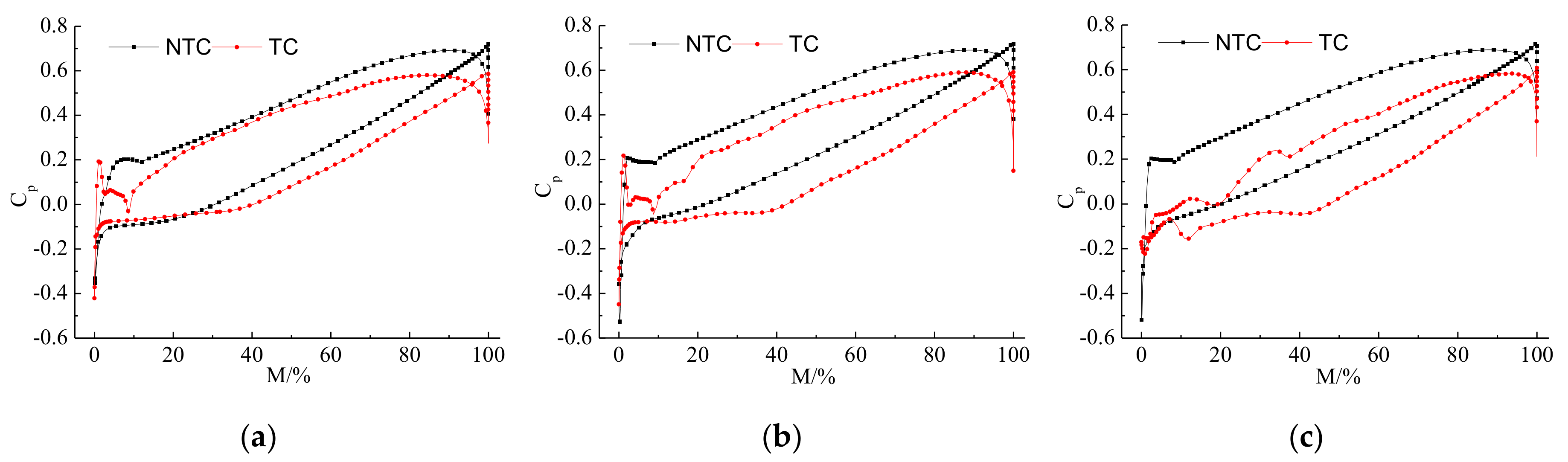
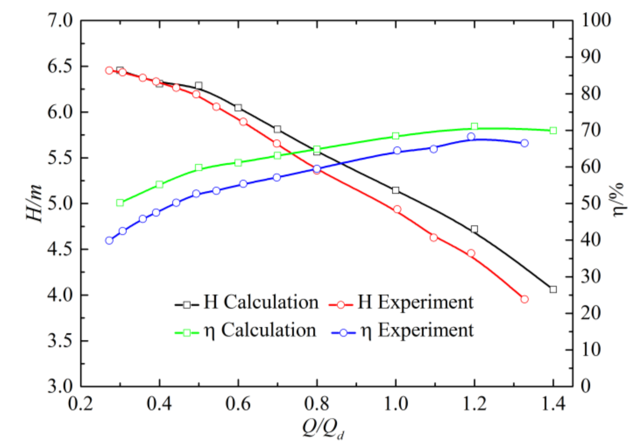
The numerical data and experiment results agreed well. Leakage vortex formed in the tip clearance led to a decrease in head and efficiency, which, respectively, decreased by 18.7% and 14.4% under the design condition. This decline became increasingly serious with the flow rate. The large negative attack angle at the blade inlet was formed and led to the appearance of the low-speed region. The static pressure distribution law near the leading edge was changed, and the static pressure coefficient of the blade was reduced.
(2)
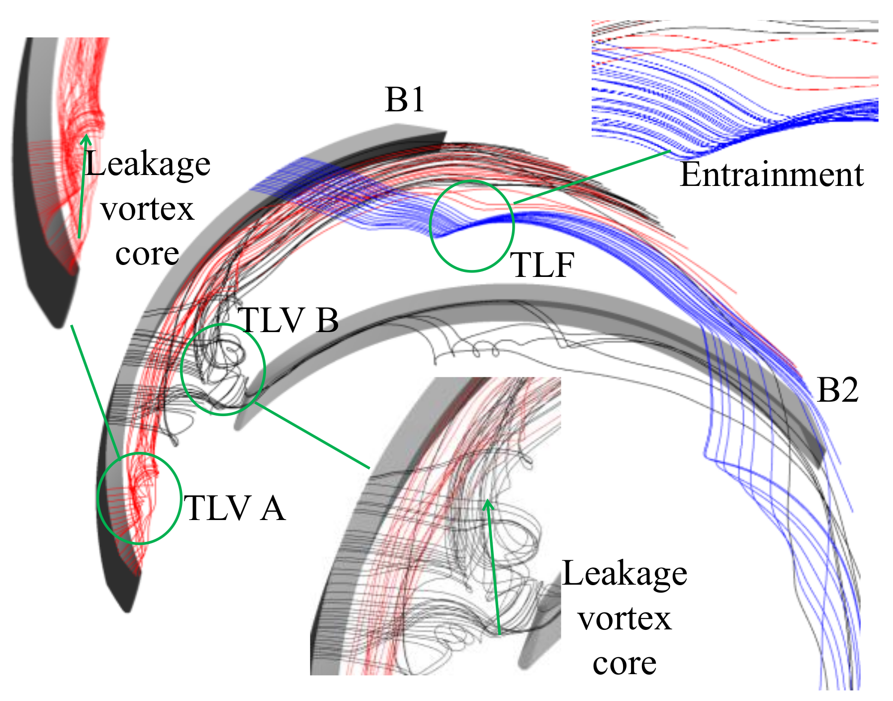
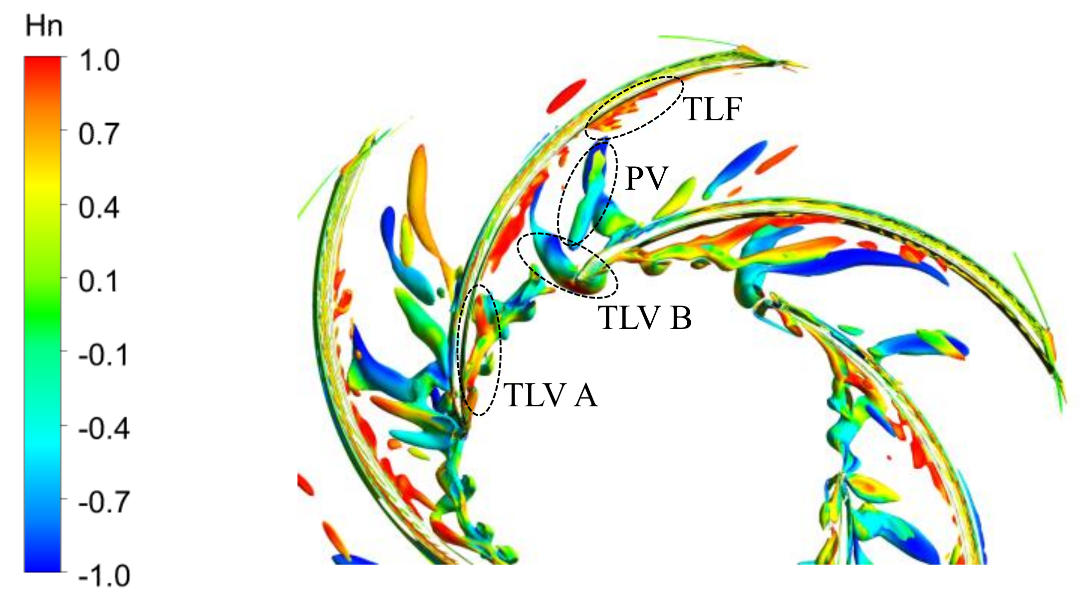
The structure of tip leakage vortex in the impeller mainly comprised TLV A formed at the leading edge, TLV B formed at the middle of the blade, and the tip leakage flow near the trailing edge. TLV A broke at approximately 35% M. The core region of TLV B extended to the leading edge of the adjacent blade. Most of the fluid was blocked by the wall; thus, fluid moved in the opposite direction and broke at approximately 60% M. The passage vortex was generated due to the deterioration of the flow field by tip leakage vortex. The entrainment effect was formed between the tip leakage flow and mainstream, and the secondary leakage flow emerged at the trailing edge of the adjacent blade.
(3)
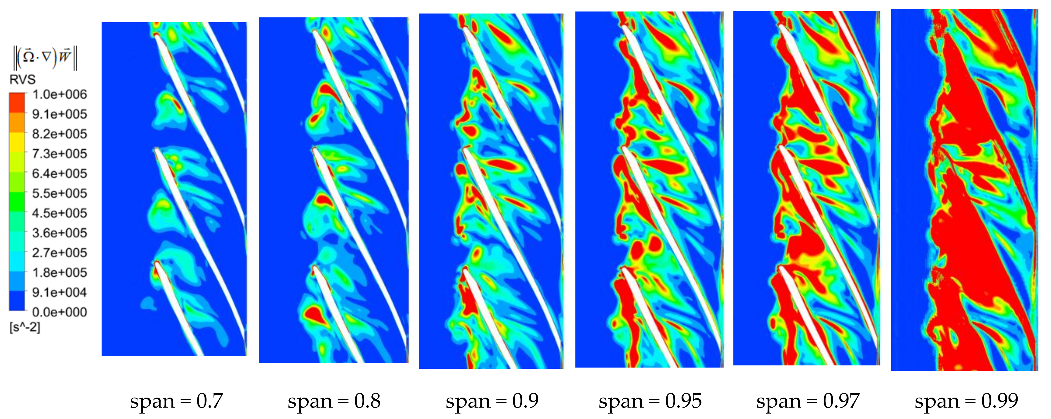
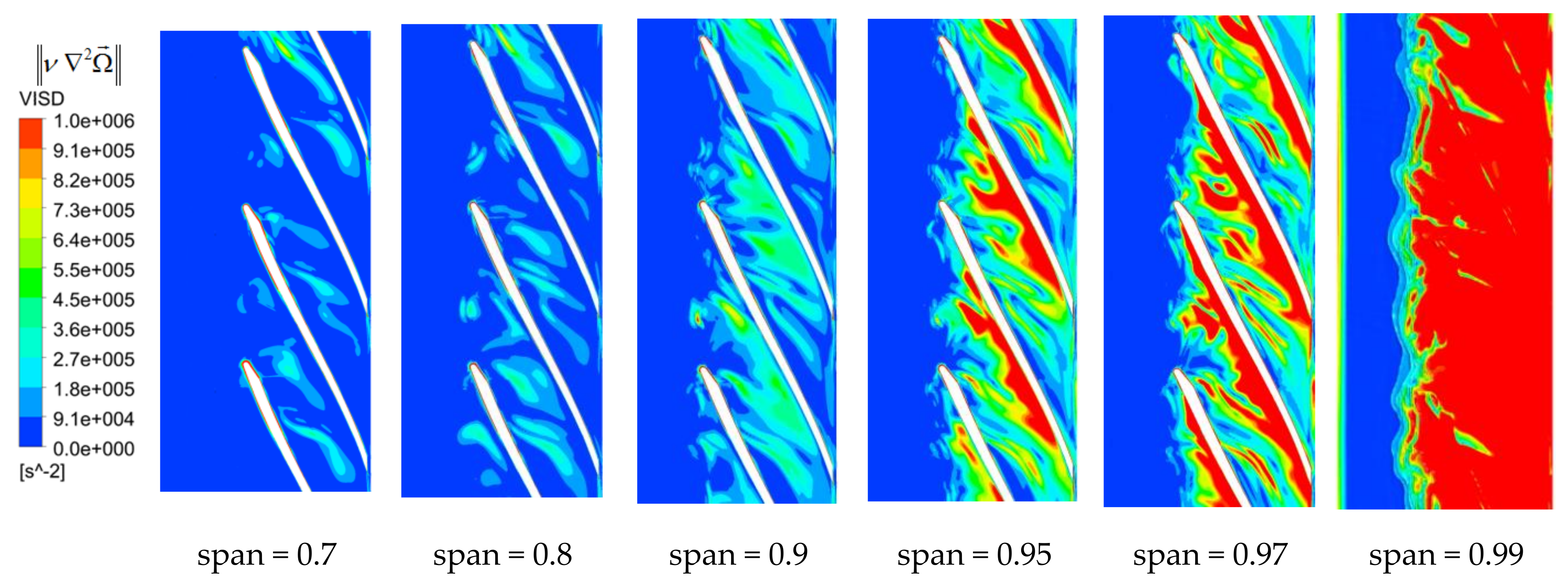
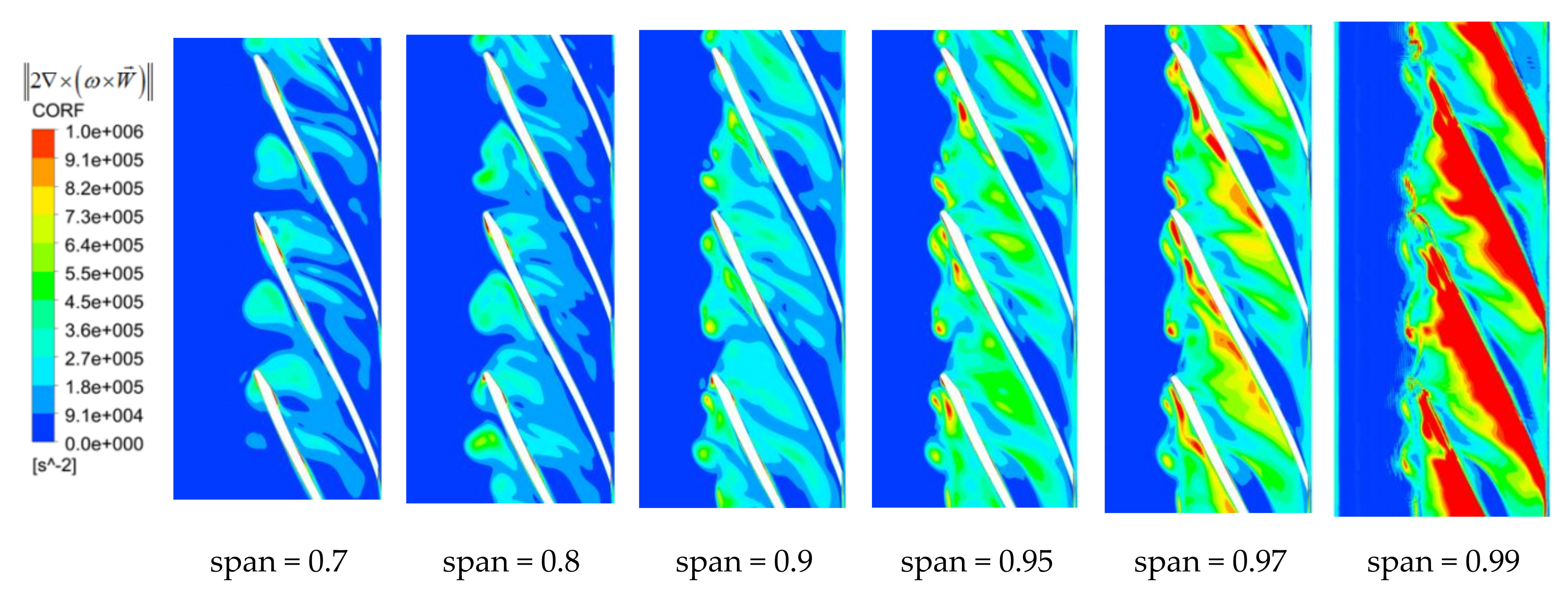
The relative vorticity transport equation was adapted to analyze the movement mechanism of the tip leakage flow. High RVS was the main reason for the formation and development of tip leakage vortex. CORF could reflect changes in vorticity due to tip leakage flow. The relative motion with different velocities was formed between micro-jet and rotating impeller and fixed shroud, so VISD became vorticity source. All terms decreased with the blade span.
(4)
The change of the structure, trajectory, and breakdown position of the tip leakage vortex would affect the performance and stability of the semi-open centrifugal pump. This provided a reference for the design of the high-performance semi-open centrifugal pump and provided ideas for the research and development of efficient and stable flow control technology. We would study the influence mechanism of other parameters, such as the strength and initial position of tip leakage vortex on the centrifugal pump, and work on reducing and restraining the effect of tip leakage vortex by flow control technology in our future research.

Author Contributions

L.W. carried out the numerical simulations, analyzed data, conducted the experiment, and wrote the first draft of the manuscript. J.L. and W.L. conceived and supervised the study and edited the manuscript. Y.Z. and W.W. wrote the manuscript. All authors reviewed the manuscript.

Funding

This research was funded by the National Natural Science Foundation of China, grant number 51679196 and the National Natural Science Foundation of China, grant number 51879216.

Conflicts of Interest

The authors declare no conflict of interest.

References

  1. Zhang, P.F.; Yuan, S.Q.; Huang, L.Y. Research Status and Development Trend of Low Specific Speed Centrifugal Pump. Pump Technol. 2004, 1, 20–24. [Google Scholar]
  2. Yang, J.L.; Lai, H.X.; Yu, X.H.; Tu, X.D. Numerical simulation of internal flow field of an unshrounded centrifugal impeller in a low specific speed pump. J. Eng. Thermophys. 2013, 34, 262–265. [Google Scholar]
  3. Boitel, G.; Fedala, D.; Myon, N. Tip clearance effects on loads and performances of semi-open impeller centrifugal pumps at different specific speeds. IOP Earth Environ. Sci. 2016, 49, 032013. [Google Scholar] [CrossRef]
  4. Michael, M.; Bernd, W.; Thévenin, D. Effect of tip clearance gap and inducer on the transport of two-phase air-water flows by centrifugal pumps. Exp. Therm. Fluid Sci. 2018, 99, 487–509. [Google Scholar]
  5. Zhang, D.S.; Shao, P.P.; Shi, W.D. Numerical simulation of Tip Leakage Vortex Hydrodynamics Characteristics in Axial Flow Pump. Trans. Chin. Soc. Agric. Eng. 2014, 45, 70–75. [Google Scholar]
  6. Zhang, H.; Chen, B.; Wang, B.Q.; Shi, C.B.; Shen, D.W. Influence of tip clearance on internal pressure fluctuation of screw centrifugal pump. Trans. Chin. Soc. Agric. Eng. 2017, 33, 84–89. [Google Scholar]
  7. Liu, Y.; Tan, L. Spatial-temporal evolution of tip leakage vortex in a mixed flow pump with tip clearance. J. Fluid Eng. 2019, 141, 081302. [Google Scholar] [CrossRef]
  8. Kaneko, M.; Tsujita, H. Numerical investigation of influence of tip leakage flow on secondary flow in transonic centrifugal compressor at design condition. J. Therm. Sci. 2015, 24, 117–122. [Google Scholar] [CrossRef]
  9. Robert, K.; Schwarz, P.; Wilkosz, B. Experimental and Numerical Investigation of Tip Clearance and Bleed Effects in a Centrifugal Compressor Stage with Pipe Diffuser. J. Turbo 2012, 135, 011005. [Google Scholar]
  10. Zhao, H.J.; Xi, G.; Duan, Y.F.; Wang, Z.H. Experimental study of tip clearance effects on performance and flow field of a centrifugal conprossor. J. Eng. Thermophys. 2018, 39, 1453–1459. [Google Scholar]
  11. Jia, X.C.; Wang, Z.M.; Cai, R.X. The Numerical Study of Tip Clearance Effects on Acrodynamic Performance in Turbomachines. J. Eng. Thermophys. 2001, 22, 431–434. [Google Scholar]
  12. Gao, L.M.; Xi, G.; Wang, S.J. Influence of Tip Clearance on the Flow Field and Aerodynamic Performance of the Centrifugal Impeller. Chin. J. Aeronaut. 2002, 3, 139–144. [Google Scholar] [CrossRef]
  13. Liu, Y.; Tan, L.; Hao, Y. Energy performance and flow patterns of a mixed flow pump with different tip clearance sizes. Adv. Mech. Eng. 2017, 10, 191. [Google Scholar] [CrossRef]
  14. Bing, H.; Cao, S.L.; He, C.L. Experimental study of the effect of blade tip clearance and blade angle error on the performance of mixed-flow pump. Sci. Chin. Technol. Sci. 2013, 56, 293–298. [Google Scholar] [CrossRef]
  15. Zhang, W.W.; Yu, Z.Y.; Zhu, B.S.; Yang, C. Study of Tip Clearance Effects on Performances and Flow Field of a Low Specific Speed Mixed-flow Pump. J. Mech. Eng. 2017, 53, 182–189. [Google Scholar] [CrossRef]
  16. Jia, X.Q.; Cui, B.L.; Zhang, Y.L.; Zhu, Z.C. Study on Internal Flow and External Performance of a Semi-open Impeller Centrifugal Pump with Different Tip Clearances. Int. J. Turbo Jet Engines 2015, 32, 1–12. [Google Scholar] [CrossRef]
  17. Farid, A.A.; Abdalla, H.M.; Abou, E.A. Effect of semi-open impeller side clearance on the centrifugal pump performance using CFD. Aerosp. Sci. Technol. 2015, 47, 247–255. [Google Scholar]
  18. Zhao, X.R.; Xiao, Y.X.; Wang, Z.W. Numerical analysis of non-axisymmetric flow characteristic for a pump-turbine impeller at pump off-design condition. Renew. Energy 2017, 115, 1075–1085. [Google Scholar]
  19. Li, J.W.; Zhang, Y.N.; Liu, K.H. Numerical simulation of hydraulic force on the impeller of the reversible pump turbine in generating mode. J. Hydrodyn. 2017, 29, 603–609. [Google Scholar] [CrossRef]
  20. Zhou, K.; Zhou, C. Unsteady effects of vortex interaction on tip leakage vortex breakdown and its loss mechanism. Aerosp. Sci. Technol. 2018, 82, 363–371. [Google Scholar] [CrossRef]
  21. Antonio, P.; Antonio, L. Effect of working conditions and diffuser setting angle on pressure fluctuation within a cetrifugal pump. Int. J. Heat Fluids Flow 2019, 75, 44–60. [Google Scholar]
  22. Gao, Y.Q.; Chu, W.L.; Zhang, H.G. The Influence of the Tip Clearance to a Low-speed Centrifugal Impeller Performance and the Flow Field Analysis of the Neat trailing edge. Mach. Des. Manuf. 2013, 9, 107–109. [Google Scholar]
  23. Li, Y.B.; Hu, P.L.; Li, R.N. Numerical Analysis for Effects of Different Blade Tip Clearance on Performance in Mixed-flow Pump. Trans. Chin. Soc. Agric. Eng. 2014, 30, 86–93. [Google Scholar]
  24. Xu, Y.; Tan, L.; Liu, Y. Pressure fluctuation and flow pattern of a mixed flow pump with different blade tip clearances under cavitation condition. Adv. Mech. Eng. 2017, 9, 1687814017696227. [Google Scholar] [CrossRef]
  25. Li, X.; Yuan, S.; Pan, Z. Dynamic Characteristics of Rotating Stall in Mixed Flow Pump. J. Appl. Math. 2013, 10, 4819–4828. [Google Scholar] [CrossRef]
  26. Lu, J.L.; Guo, L.; Wang, L.K.; Wang, W.; Guo, P.C.; Luo, X.Q. Research on the Unsteady Flow of Tip Clearance in Semi-open Impeller Centrifugal Pump. Trans. Chin. Soc. Agric. Eng. 2019, 50, 163–172. [Google Scholar]
  27. Iwakiri, K.; Furukawa, M.; Ibaraki, S.; Tomita, I. Unsteady and three-dimensional flow phenomena in a transonic centrifugal compressor impeller at rotating stall. In Proceedings of the ASME Turbo Expo 2009: Power for Land, Sea, and Air, Orlando, FL, USA, 8–12 June 2009; pp. 1611–1622. [Google Scholar]
  28. Zhao, H.J.; Wang, Z.H.; Xi, G. Unsteady flow structures in the tip region for a centrifugal compressor impeller before rotating stall. Sci. China Technol. Sci. 2017, 06, 122–132. [Google Scholar] [CrossRef]
  29. Zhang, H.Z.; Yang, C.; Yang, D.F.; Wang, W.L. Investigation on the Stall Inception Circumferential Position and Stall Process Behavior in a Centrifugal Compressor with Volute. J. Eng. Turb. Power. 2019, 141, 021030. [Google Scholar] [CrossRef]
  30. Buren, T.V.; Whalen, E.; Amitay, M. Eddies, stream and convergence zones in turbulent flows. Phys. Fluids 2015, 30, 512–516. [Google Scholar]
  31. Tristan, F. Dynamics of the Cavitation Processing Vortex Rope for Francis Turbines at Part Load Operating Conditions; EPFL: Lausanne, Switzerland, 2016. [Google Scholar]
  32. Anup, K.C.; Lee, Y.H.; Thapa, B. CFD study on prediction of vortex shedding in draft tube of Francis turbine and vortex control techniques. Renew. Energy 2016, 86, 1406–1421. [Google Scholar]
  33. Lu, J.L.; Wang, L.K.; Liao, W.L.; Zhao, Y.P.; Ji, Q.F. Entropy Production Analysis for Vortex Rope of a Turbine Model. J. Hydraul. Eng. ASCE 2019, 50, 233–241. [Google Scholar]
  34. Ji, B.; Luo, X.W. Numerical analysis of unsteady cavitating turbulent flow and shedding horse-shoe vortex structure around a twisted hydrofoil. Int. J. Multiphas. Flow 2013, 51, 33–43. [Google Scholar] [CrossRef]
  35. Huang, R.; Ji, B.; Luo, X.W. Numerical investigation of cavitation-vortex interaction in a mixed-flow waterjet pump. J. Mech. Sci. Technol. 2015, 29, 3707–3716. [Google Scholar] [CrossRef]
  36. Ji, B.; Luo, X.W.; Arndt, R.E.A. Numerical simulation of three dimensional cavitation shedding dynamics with special emphasis on cavitation-vortex interaction. Ocean Eng. 2014, 87, 64–77. [Google Scholar] [CrossRef]
  37. Liu, Y.B.; Tan, L. Tip clearance on pressure fluctuation intensity and vortex characteristic of a mixed flow pump as turbine at pump mode. Renew. Energy 2018, 129, 606–615. [Google Scholar] [CrossRef]
Figure 1. Computational domain of the pump.
Applsci 09 05244 g001
Figure 2. Impeller meridional shape.
Applsci 09 05244 g002
Figure 3. Closed test loop.
Applsci 09 05244 g003
Figure 4. Mesh analysis for NTC (without tip clearance) and TC (tip clearance). (a) NTC, (b) TC.
Applsci 09 05244 g004
Figure 5. Computational domain grids of a centrifugal pump. (a) Impeller, (b) Leading edge of the blade, (c) Trailing edge of the blade.
Applsci 09 05244 g005
Figure 6. Comparison of the head between experimental and numerical results.
Applsci 09 05244 g006
Figure 7. External characteristics of TC and NTC.
Applsci 09 05244 g007
Figure 8. Streamline distribution of NTC on different span planes. (a) Span = 0.05, (b) Span = 0.5, (c) Span = 0.95.
Applsci 09 05244 g008
Figure 9. Streamline distribution of TC on different span planes. (a) Span = 0.05, (b) Span = 0.5, (c) Span = 0.95.
Applsci 09 05244 g009
Figure 10. Relative flow angle distribution of the blade leading edge on different span planes. (a) Span = 0.05, (b) Span = 0.5, (c) Span = 0.95.
Applsci 09 05244 g010
Figure 11. Static pressure coefficient distribution on the blade surface on different span planes. (a) Span = 0.05, (b) Span = 0.5, (c) Span = 0.95.
Applsci 09 05244 g011
Figure 12. Vortex structure defined by the Q criterion (Q = 1.0 × 10⁵ s−2).
Applsci 09 05244 g012
Figure 13. Tip streamline’s distribution of tip clearance vortex.
Applsci 09 05244 g013
Figure 14. Distribution of relative vortex stretching term on different span planes.
Applsci 09 05244 g014
Figure 15. Distribution of Coriolis force term on different span planes.
Applsci 09 05244 g015
Figure 16. Distribution of viscous diffusion term on different span planes.
Applsci 09 05244 g016
Table 1. Geometrical parameters of the pump.
ParametersValueParametersValue
Impeller inlet diameter, D1100 mmImpeller outlet diameter, D2232 mm
Impeller outlet width, b216 mmBlade number, Z6
Blade inlet angle, β116.6°Blade outlet angle, β218.6°
Wrag angle, Φ99.4Blade thickness, T4 mm
Impeller radius of suction surface88 mmImpeller radius of pressure surface92 mm
Table 2. Elements number in the computational domain.
Tip Clearance/mmInlet Pipe/106Impeller/106Vaneless Diffuser/106Total/106
00.454.520.455.42
10.596.100.627.21

