Article

Reinforcement Learning-Based Anti-Jamming in Networked UAV Radar Systems

1
College of Electronic Science, National University of Defense Technology, Changsha 410073, China
2
Artificial Intelligence Research Center, National Innovation Institute of Defense Technology, Beijing 100010, China
*
Author to whom correspondence should be addressed.
Appl. Sci. 2019, 9(23), 5173; https://doi.org/10.3390/app9235173
Submission received: 20 October 2019 / Revised: 22 November 2019 / Accepted: 25 November 2019 / Published: 28 November 2019
(This article belongs to the Special Issue Multi-Channel and Multi-Agent Signal Processing)

Abstract

:
The networked unmanned aerial vehicle (UAV) radar system may exploit inter-UAV cooperation for enhancing information acquisition capabilities, meanwhile its inter-UAV communications may be interfered with by external jammers. This paper is devoted to quantifying and optimizing the anti-jamming performance of networked UAV radar systems in adversarial electromagnetic environments. Firstly, instead of using the conventional metric of signal-to-interference ratio (SIR), this paper explores use of the theory of radar information representation as the basis of evaluating the information acquisition capabilities of the networked UAV radar systems. Secondly, this paper proposes a modified Q-Learning method based on double greedy algorithm to optimize the anti-jamming performance of the networked UAV radar systems, through joint programming in the frequency-motion-antenna domain. Simulation results prove the effectiveness of the algorithm in two different networking scenarios.

1. Introduction

A radar countermeasure is an important part of an electronic countermeasure [1]. An effective radar countermeasures can deal with the jamming of various electronic equipment and signal modes [2]. At present, the mainstream countermeasure methods are as follows: 1. Game theory: establish a network model of multiple agents and use game theory to model the adjustment of policies between jammer and radar as Stackelberg game. Through analyzing and solving the game equilibrium solution (such as the Nash equilibrium), we can obtain the optimal transmission power and other policies for users to realize anti-jamming [3,4,5]. 2. Physical layer security: this is a supplement to traditional cryptography-based methods. Users usually generate noise signals to confuse potential eavesdroppers, which significantly improves the quality and reliability of secure communication between legitimate terminals [6,7]. 3. Machine learning: intelligent countermeasures represented by reinforcement learning have been widely used in recent years. Reinforcement learning realizes the policy iteration through the interaction between agent and environment and finally generates a reasonable policy set [8,9]. With the progress of electronic jamming, the traditional jammer with single function and fixed working mode is promoted to intelligent jamming of multi-function, multi-parameter and variable working mode [10]. Therefore, the intelligent radar system becomes the focus of anti-jamming research [11]. Because the traditional radar system often uses passive methods such as a waveform library to identify the jamming form, this results in poor real-time policy [12]. When it deals with new forms of jamming, the utility of this approach is limited. Therefore, an intelligent radar system needs to generate real-time policies under the condition of flexible jamming forms.
Radar countermeasure of an intelligent unmanned aerial vehicle (UAV) swarm is an effective form of intelligent radar countermeasure. Unlike the mission planning of general multi-radar systems, swarm intelligence UAV technology pays more attention to the individual UAV with a simple structure and limited energy. Through internal interaction and swarm control, the detection capability of a single UAV in a swarm is greatly promoted, and it is more flexible than traditional radar. A UAV has the characteristics of good concealment, flexible motion and rapid networking. An intelligent UAV cannot only perform common tasks such as surveillance of unknown areas, protection of key targets, territorial investigation and so on, and more flexible operations such as radar networking can be used to achieve radar countermeasures by airborne small radar [13]. Radar networking based on a UAV swarm greatly improves the ability of radar information acquisition by properly distributing radar stations with different systems, different frequency bands, different working modes, and linking them into networks.
However, the following design considerations should be taken into account in intelligent networked UAV radar systems:
1.
Intelligent UAVs may be energy-limited. The energy modules on most UAVs may pose a major constraint on their motion ability. Meanwhile, when the UAV carries a radar payload to perform detection tasks, its motion and adaptation of the radar parameters may introduce considerable energy consumption. Therefore, a UAV may need to strike a beneficial trade-off between the motion energy and energy consumed by the radar.
2.
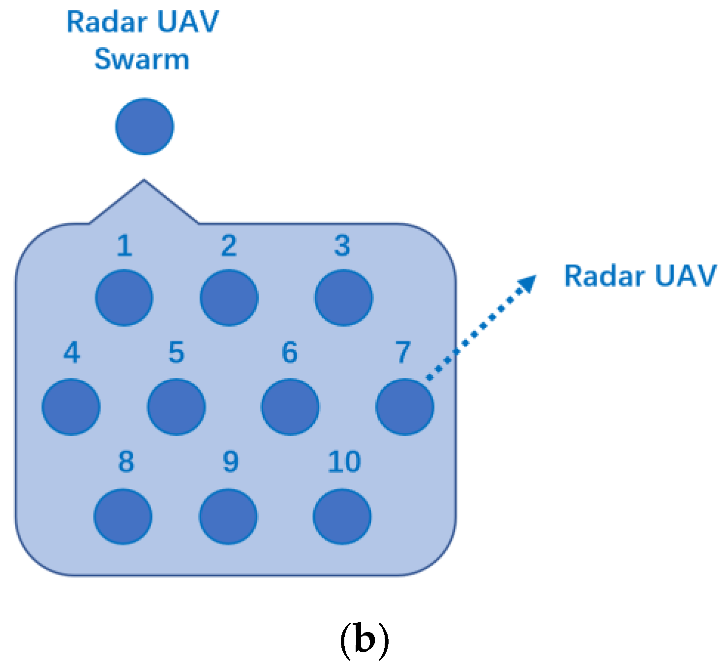
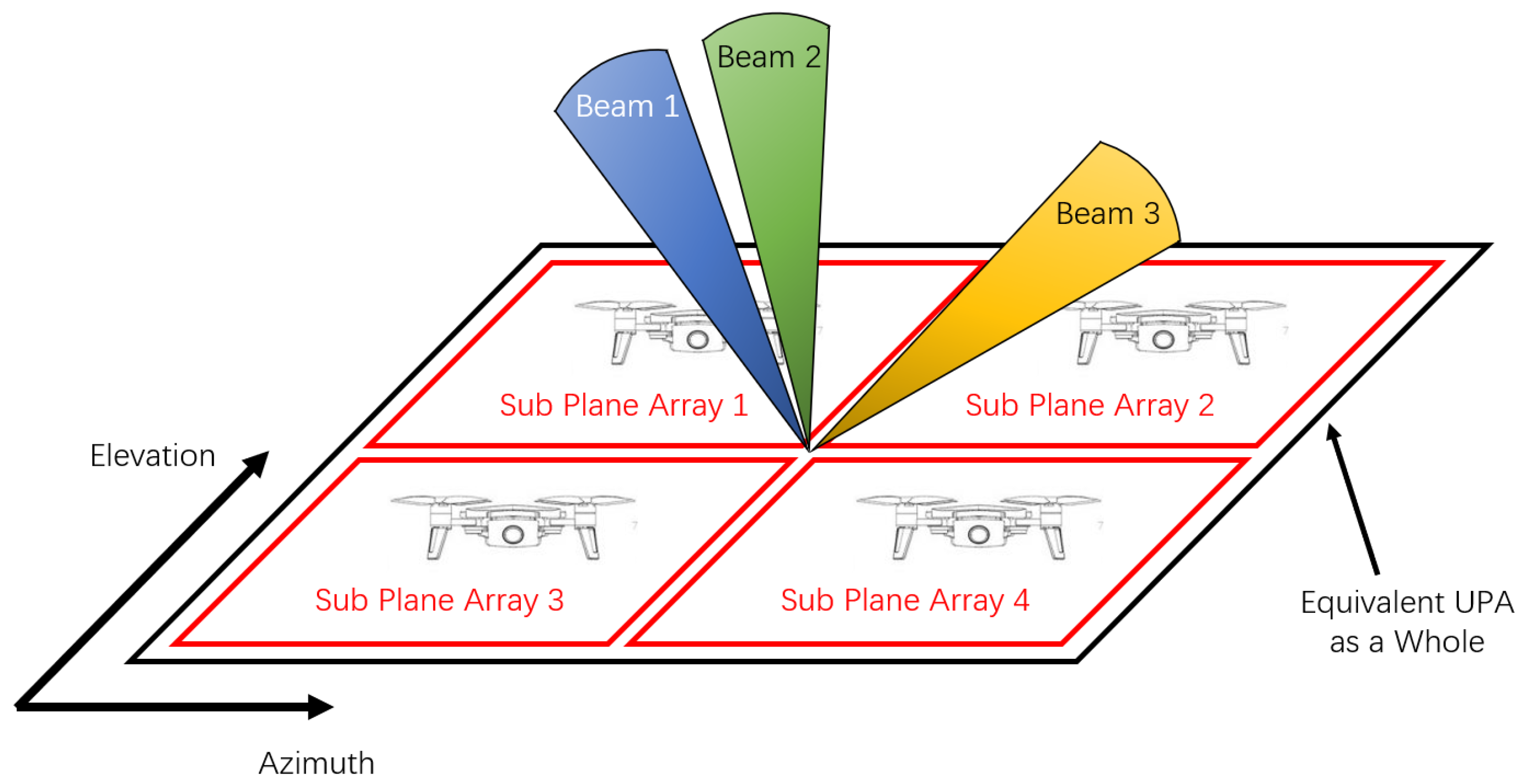
The antenna performance of smart UAVs may be limited. Due to the limited volume and load capacity of the UAV, the number of array elements may be limited, resulting in poor spatial resolution. However, the beam width adopted by radar in certain tasks may demand high spatial resolutions, e.g., when measuring angle by beam scanning method. Therefore, the networked UAV radar system should exploit the distributed UAV cooperation to overcome the antenna constraint of a single UAV.
3.
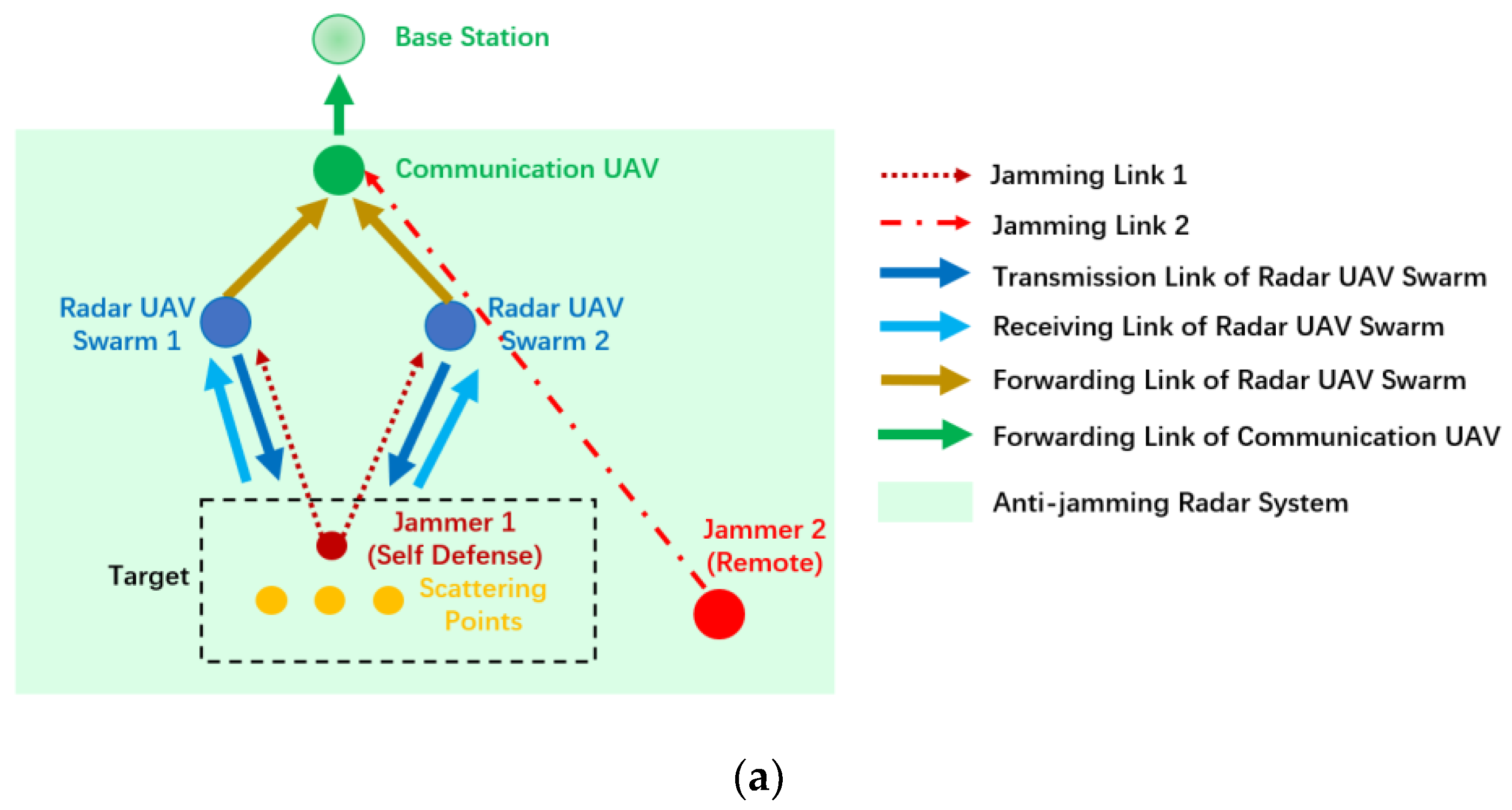
The topology of the networked UAV radar system may be complex. In order to comprehensively analyse the received information, the target data need to be transmitted to a data fusion center. Therefore, secondary forwarding devices such as relays may be applied during long-range communications. The networked UAV radar system should control complexity of information transmission process, and control the risks of information interception and jamming.
In order to address the aforementioned design concerns, this paper proposes the use of reinforcement learning for training the behavior of the networked UAV radar systems. Although reinforcement learning is being adopted as an effective method in radar anti-jamming, there is a lack of research on multi-parameter programming in the literature. Meanwhile, most researchers only regard signal-to-interference ratio (SIR) as the criterion of the reward, which may not fully reflect the ability of the radar system to acquire target information. Therefore, this paper applies information representation theory to evaluate the capability of radar information acquisition.
Specifically, this paper investigates the radar countermeasures under the conditions of malicious jamming, constrained UAV motion, fewer airborne radar elements, and complex topology of UAV networking. We construct two radar networking methods, introduce the theory of radar information representation, and use modified Q-Learning based on a double greedy algorithm to generate anti-jamming policies. The simulation results will prove the effectiveness of the algorithm.
The contributions of this paper are as follows:
1.
A radar countermeasure system based on intelligent networked UAV swarms is established. Compared with the existing radar countermeasure models, our model introduces joint programming of UAV-borne radar to make full use of various degrees of freedom, where the policies can be generated from three dimensions of antenna, frequency and position.
2.
Two UAV radar networking modes are proposed and implemented. The simulation results show that the proposed algorithm can realize the effective programming of radar system parameters in both modes.
3.
This paper introduces a novel reward design by the information representation method to quantify the information received by the networked UAV radar systems.
The structure of this paper is organized as follows: Section 2 introduces the related works of UAV networking and anti-jamming based on reinforcement learning. Section 3 is the system modeling. We will introduce the intelligent UAV swarm networking model and the phased array beam synthesis method with limited phase coding bits. Section 4 introduces DGQL (Double-Greedy Reinforcement Learning) algorithm based on information representation. Section 5 gives the simulation results and analysis, which proves the effectiveness of the DGQL. Section 6 summarizes the contribution of this paper.

2. Related Works

UAVs have been used widely in the anti-jamming field. A UAV is designed in [14] to avoid the jamming of the aerial jammer to the channel by differential game method. This method could generate the optimal policy to avoid jamming. A UAV was used in [15] to send onboard units information, which improved the communication performance of vehicular ad-hoc networks in the presence of intelligent jammer. As for swarm UAV, Li Haitao et al. proposed a countermeasure model based on airborne cognitive radio and used an improved energy detection method to detect jamming [16]. Li Zhiwei et al. presented a method of using a software-defined network (SDN) to counter software-defined radio (SDR) [17]. A new type of network using a dual-controller generation policy was proposed. Rahmes Mark et al. designed a multi-UAV countermeasure system and used Q-Learning algorithm to generate radar transmitting frequency [18]. Cevik Polat et al. reduced the resource allocation problem in electronic countermeasures to an optimal allocation problem, and proposed a resource allocation algorithm based on particle swarm optimization theory [19].
At present, there is some research on radar reinforcement learning, mainly in the field of deep reinforcement learning. An intelligent radar countermeasure method was studied in [20] under the condition where the number of working modes of multi-functional radar was unknown. The jamming receiver recognized the working state of the radar by processing the information, and then generated a new effective jamming pattern. Liu Pengfei et al. combined reinforcement learning with cognitive radar in [21], so that transmitting and receiving could adapt to an unknown dynamic environment. It explained how to realize spectrum allocation of automotive radar in reinforcement learning-based cognitive radar system. You Shixun et al. simulated an electronic attacker as a UAV and a defender as an observatory in [22], where the UAV needed to detect targets. A deep deterministic policy gradient (DDPG) algorithm based on variational Bayesian estimation was designed to train the motion policy of the UAV. Wang Li et al. proved that some basic reinforcement learning algorithms could be successfully applied to dynamic detection of multiple-input-multiple-output (MIMO) radar with unknown environment and unknown number of targets [23]. Deep learning was used in [24] to discuss channel selection when wideband radar signals coexist with narrowband communication signals in the communication systems.
Some progress has also been made in the research of the combination of jamming and physical layer security. For example, Furqan Jameel et al. reviewed the latest work of cooperative relaying and jamming in detail [6]. These technologies are used to protect wireless transmission from eavesdropping nodes. They explained that using cooperative security can improve the physical layer security, and proposed some methods and conclusions to improve the wireless communication performance based on physical layer security. For example, relay positioning can be further explored, multi-cellular design can be further studied, etc. This paper is of great significance to the design a security scheme in the 5G communication network. At the same time, Huo Yan et al. summarized the jamming policies in the physical layer of wireless communication and classified the jamming policies in [25], which provided a theoretical basis for the design of jamming policy in a wireless communication system.
From the literature, it may be concluded that frequency-domain anti-jamming techniques have been widely adopted in the field of anti-jamming of UAV radar networking, but the degrees of freedom exhibited in motion and antenna arrays of networked-UAV radar systems are not fully exploited. Secondly, the radar anti-jamming techniques proposed in the literature generally adopted SIR or SNR as the reward in reinforcement learning, while it may not fully capture the information acquisition ability of the radar. In this paper, the beam synthesis, networking and autonomous motion in networked-UAV radar systems are jointly optimized, with the aid of radar information representation theory and reinforcement learning.

3. System Model

3.1. Modeling of Radar Unmanned Aerial Vehicle (UAV) Swarm Networking

Spectrum resource allocation is a common problem in radar countermeasures. In the actual scenario, the spectrum resources are very limited because there are numerous electronic devices working at various modes. The setting of parameters in a radar system, such as position and antenna, needs to be tuned to avoid jamming effectively.
Traditional ground-based radar has the advantages of high power, long detection distance and narrow beam width. However, its mobility poses a threat for real-time detection in case of jamming. In comparison, small array radars carried by networked UAVs may realize swift position shift, phased array element combination, relatively flexible beam scanning and conversion between multiple detecting modes. Not only can UAVs in one single swarm cooperate with each other to synthesize beams, but also cooperate among multiple swarms. Thus, many parameters of targets can be observed simultaneously, which greatly improves the detection efficiency of the radar system.
However, due to the energy constraints, the power and moving range of UAVs should be considered for effective applications. When multiple swarms work at the same time, each swarm needs to send the data back to the control center. The multi-channel data can be analyzed synthetically by the control center to obtain multi-dimensional information. In case the UAV performs tasks in remote areas, communication UAV may serve as a mobile relay to assist the data transmission. As an effective radar countermeasure, jamming systems may be used to decrease the efficiency of the radar system, where both the UAV swarm and the relay may be jammed.
Against the above background, a radar countermeasure system composed of multi-agents is established in this paper. The system framework is shown in Figure 1a. The system includes 5 kinds of agents: jammer, radar UAV swarms, communication UAV, base station and target. Among them, radar UAV swarms, communication UAV and base station form the radar systems together. The objective of is to maximize the target information acquisition in different networking modes by adjusting the parameters of the radar system. In Figure 1b, the internal schematic diagram of a radar UAV swarm is given. A radar UAV swarm consists of a number of UAVs, and each UAV carries an antenna array. Radar UAV swarms are responsible for transmitting electromagnetic waves to detect targets and receiving signals. This process is called the transmission link of the radar UAV swarm. It is assumed that the distance between UAVs is much smaller than the distance from the whole UAV swarm to the target.
Specifically, the UAVs in a swarm can form a uniform linear array (ULA) or uniform plane array (UPA) by changing their arrangement to synthesize beams. However, due to the limited array volume of the UAV, its phase shifter cannot have a high coding bit like a large ground-based phased array radar. Therefore, this paper explores the beam synthesis method under low-bit phase coding, which will be introduced in Section 3.2.
The UAVs in a swarm transmit linear frequency modulation (LFM) signals with the same waveform parameters. Therefore, the UAVs in a swarm are strictly synchronized, where each UAV swarm can play a similar role to a complete array radar. In order to simplify the signal modeling process, we set up two UAV swarms in frequency division multiplexing mode. When transmitting signals, the frequency bands occupied by two radar UAV swarms only need to be expressed by carrier frequency f c and bandwidth b . Radar UAV swarm 1 occupies the frequency range of [ f c b / 2 , f c ) , and radar UAV swarm 2 occupies the frequency range of ( f c , f c + b / 2 ] . When the mission is determined, the position of the UAV swarm remains unchanged, and the transmitting frequency, forwarding frequency and antenna pattern are tunable.
Since the two radar UAV swarms need to transmit data back to the base station for comprehensive analysis, after receiving the target echo the two radar UAV swarms need to convert part of the received signal within the passband into the communication UAV using the frequency difference of Δ f . This process is called forwarding link of radar UAV swarm. The reason for frequency conversion is to reduce the interference between transmission link and forwarding link. After frequency conversion, the signal still has two main parameters: f c * and b * . f c * is the carrier frequency after frequency conversion, and b * remains unchanged. Frequency division multiplexing mode is still used for both signals.
The reason for setting up communication UAV is that due to the energy constraints of UAV, the two radar UAV swarms need to allocate most of the power on the transmission link and minimize the energy cost of the forwarding link. The forwarding power cannot help send data directly back to a distant base station. Therefore, the communication UAV is responsible for collecting data from two signals and forwarding them to the base station. In this paper, the transmission link from communication UAV to base station is not considered. In order to avoid jamming better, the position of communication UAV is tunable. System parameters are shown in Table 1.

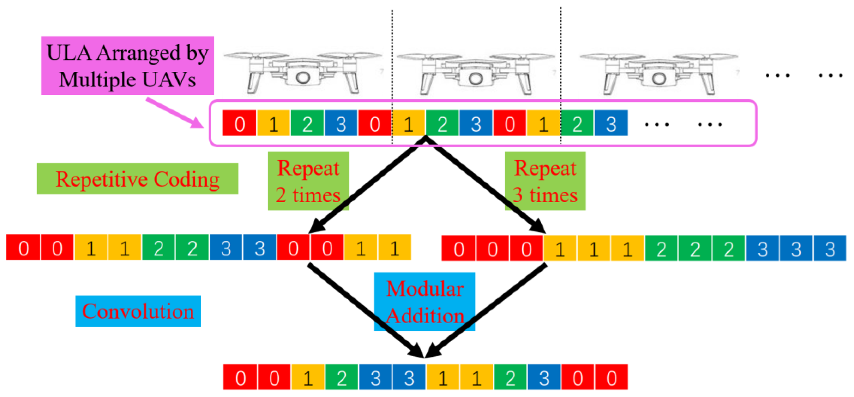
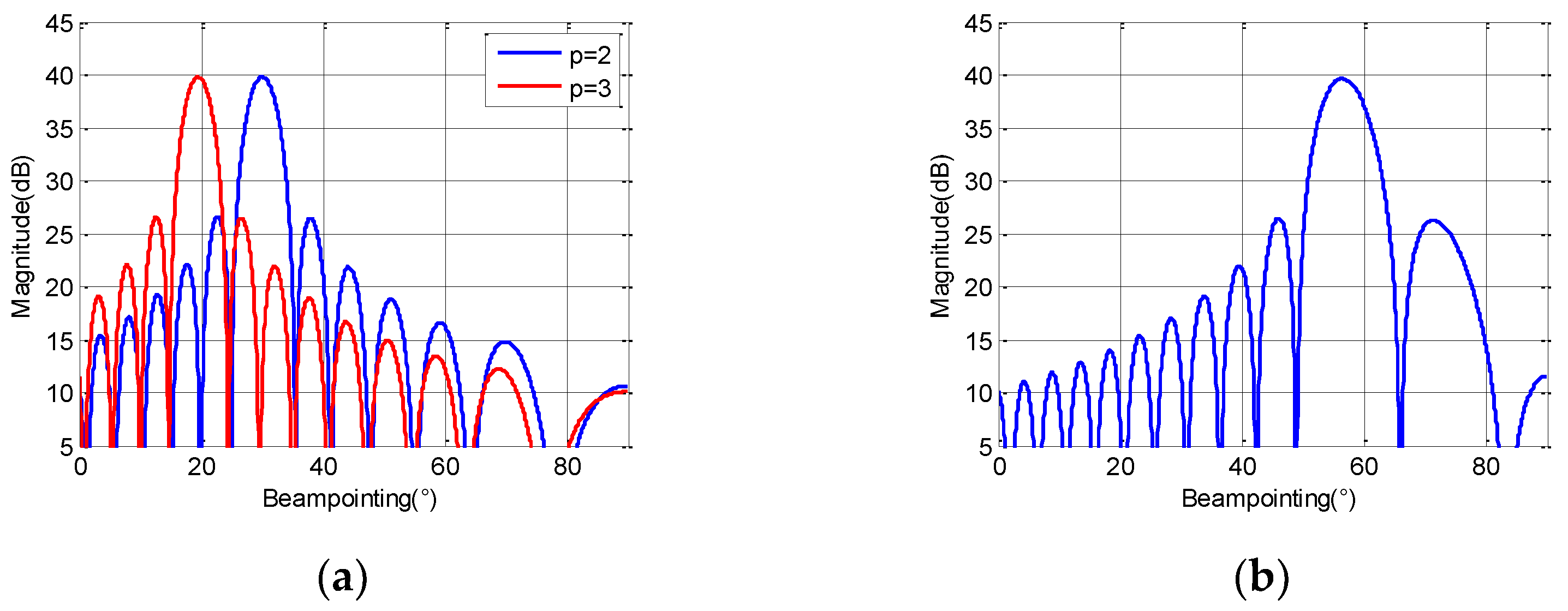
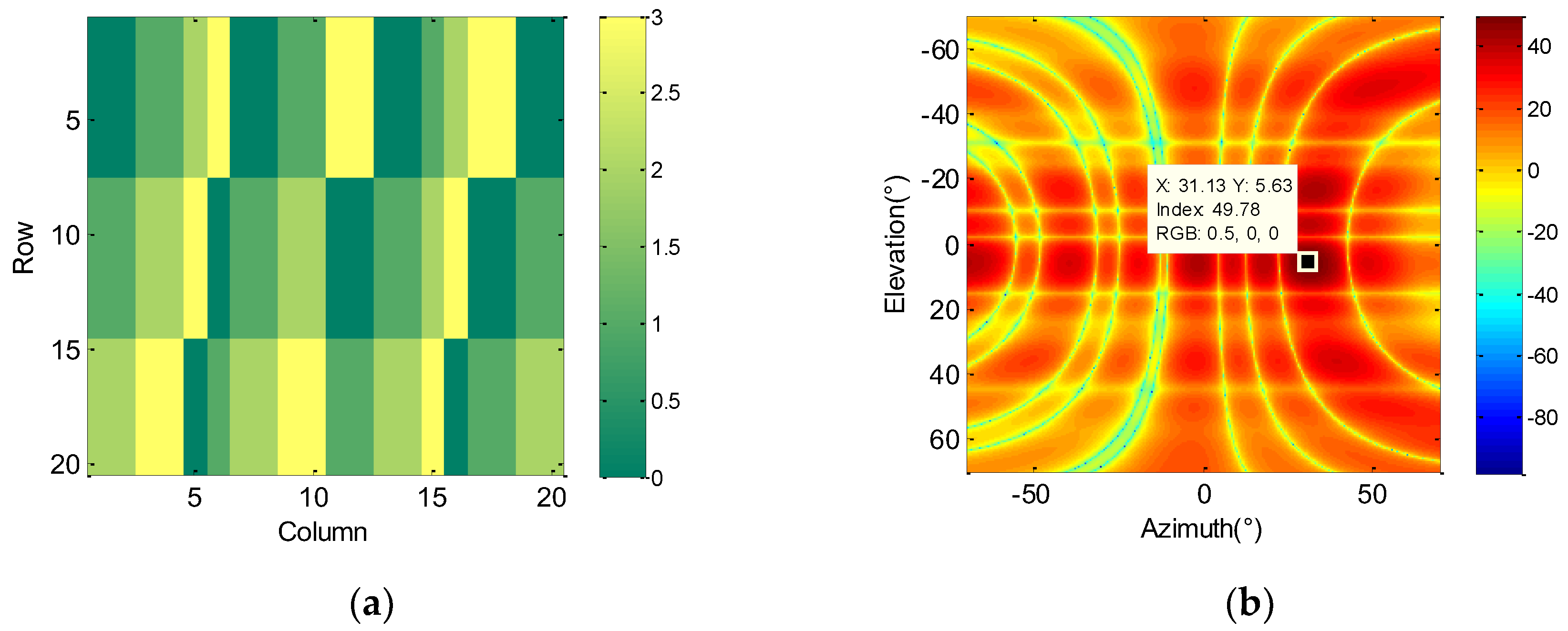
3.2. Beam Synthesis Method under Low-Bit Phase Array

This section introduces the beam synthesis method used in this paper. For phased array antennas, the phase shifter determines the precision of beam pointing. The higher the bit number of the phase shifter, the smaller the step of the phase difference between adjacent elements and the smaller the step of the synthesized beam pointing. Thus, the phase shifter used in most ground-based radars is large and expensive. Due to the limited size and load capacity of UAVs, the performance of a phase shifter is also very limited. There are many ways to achieve phased array miniaturization and beam synthesis with low-bit phase difference. The development of metamaterial is just an example [26]. In this paper, the antenna material of the UAV radar is not discussed. We only focus on the relatively flexible beam synthesis method for a UAV under low bit (2–3 bit) conditions.
A phased array antenna can control the beam pointing by controlling the phase of the array elements, which is a common method in an electric scanning antenna system. At present, one-dimensional phased array and two-dimensional phased array are widely used. They are composed of uniform linear array (ULA) and uniform plane array (UPA). ULA can realize beam scanning in a certain plane, while UPA can realize beam scanning in two-dimensional space. In order to simplify the model, without loss of generality, we first consider the low-bit beam synthesis method of ULA. Assuming that the UAVs in a swarm are arranged to form a ULA, the elements carried by each UAV may independently switch each element on or off.
It is assumed that the phase shifter can uniformly take values between 0 ° 360 ° at intervals of 360 ° / 2 M when the coding number of phase shifters M is determined. To facilitate the representation of the discrete phase, we replace the phase values of 0 ° 360 ° with the code values of 0 , 1 , 2 , , 2 M 1 , respectively. According to [27], two methods of repetitive coding and convolution can be applied. The repetitive coding method is performed by repeating the coded values in the ULA elements, and the convolution method is to perform the addition of the repeated codes, which corresponds to the convolution of the antenna pattern.
According to the convolution principle of the antenna pattern, if the beam pointings corresponding to the two different coding modes are θ 1 and θ 2 respectively, then the beam pointing after the code modular addition is pointed to θ 0 .
sin θ 0 = sin θ 1 + sin θ 2
This process is shown in Figure 2.
The spacing of array elements is d , the number of coded bits is M , the operating wavelength is λ = 2 M d , and the number of coding repetitions is p . In the real scenarios, the operating wavelength is related to the frequency. It is only set here to facilitate the interpretation of the beamforming principle.
Consider a case of 10 UAVs in a swarm and each UAV carries five elements, the number of ULA elements is N = 50 . The spacing of array elements is d = 1 cm and M = 2 , Figure 3a shows the antenna pattern when p = 2 and p = 3 , respectively. Figure 3b shows the antenna pattern after the two coding modes are added in Figure 3a. Since the beam pointing of a phased array antenna is:
sin θ = φ λ 2 π d
where φ = 2 π / 2 M , and λ = 2 M d , thus:
θ = arcsin ( 1 / p )
The synthesized beam is now pointed to:
θ 0 = arcsin ( 1 2 + 1 3 ) = 56.44 °
From Figure 3b, the effectiveness of (1) can be verified. Therefore, this paper applies the antenna pattern generated by repetitive coding and convolution method under 3-bit condition to simulate. According to the basic theory of phased array antennas, the beam width can be controlled by the number of elements. When a wider beam needs to be generated, the UAV swarm can choose to turn off some of the array elements to reduce the number of elements. There is a trade-off for the antenna pattern policy. For a radar UAV swarm, both the antenna pointing and the mainlobe width can be tuned. When a pattern with a wide mainlobe width is selected, its antenna gain also decreases. Therefore, the algorithm does not always choose the policy of a wide mainlobe antenna pattern.
In order to make the beam synthesis method more universal, we continue to consider the low bit beamforming method when the UAVs form a uniform plane array. Suppose the UAV swarm is arranged in an equivalent UPA as shown in Figure 4.
In Figure 4, the red box represents the UPA carried by each UAV, and they constitute the equivalent UPA as a whole. The equivalent UPA is represented by a black box. Because the element number of an equivalent UPA is much more than that of a single UAV, it has better beam performance, such as higher gain and narrower mainlobe width. The equivalent UPA can adjust the azimuth and elevation of the beam independently to realize the beam synthesis in two-dimensional space.
According to [28], the low-bit beam synthesis method of ULA can be extended to UPA. We assume that elevation is θ , azimuth is ϕ , the equivalent UPA is of m rows and n columns and the number of coded bits is M . Thus, the two-dimensional radiation pattern can be written as:
| E 1 ( θ , ϕ ) | sin [ n 2 ( 2 π p d 1 λ cos θ sin φ 2 π 2 M ) ] sin [ 1 2 ( 2 π p d 1 λ cos θ sin φ 2 π 2 M ) ]
| E 2 ( θ ) | sin [ m 2 ( 2 π q d 2 λ sin θ 2 π 2 M ) ] sin [ 1 2 ( 2 π q d 2 λ sin θ 2 π 2 M ) ]
We assume that p = [ p 1 , p 2 , , p a ] represents the column coding (control azimuth) with the repetition times of p 1 , p 2 , , p a respectively, and q = [ q 1 , q 2 , , q b ] represents the row coding (control elevation) with the repetition times of q 1 , q 2 , , q b , respectively. According to the equivalent substitution theory of Figure 4 in [28], the elevation and azimuth of the beam can be designed by the following formula:
sin θ 0 = λ d 2 × 2 M i = 1 b 1 q i
sin φ 0 = λ d 1 cos θ × 2 M k = 1 a 1 p k
In order to show the above process more vividly, it is proved by the following simulation. The simulation parameters are as follows: m = n = 2 , p = [ 5 ] , q = [ 3 , 2 ] , M = 2 , frequency is 10 GHz, element space d = 1 cm. Based on (7) and (8), we can get θ 0 = 6.15 ° , ϕ 0 = 31.87 ° . The simulated coding scheme is shown in Figure 5a, and the two-dimensional beam is shown in Figure 5b. At this time, the simulated beam pointing of two-dimensional beam is 5.63 ° (elevation) and 31.13 ° (azimuth) which is basically in line with theoretical design. In this way, we use four phase values only to obtain relatively high beam synthesis accuracy. It is shown that the low-bit beam synthesis method can also be applied to the equivalent UPA.

4. Algorithm Design

Based on the modelling of Section 3, this section aims to solve the anti-jamming problem of UAV radar networking by introducing information representation theory and a modified Q-Learning algorithm. The objective of system optimization is to generate a reasonable multi-parameter policy of a radar system through the algorithm, so as to achieve the maximum information acquisition capability of a radar in any given jamming form. In the design of reinforcement learning algorithm, the rationality of the reward model is critical to the evaluation of generated policy.
Taking the following radar angle measurement case as an example, the target has multiple scattering points distributed in the azimuth direction, while the radar needs to measure the receiving angle of a strong scattering point from the target. In order to improve the angle measurement accuracy, a narrow beam should be formed, but this may result in a low SIR as the beam may not cover the target area. Therefore, using SIR as the reward function may not capture the information acquisition capability of the radar system. Therefore, we introduce the theory of radar information representation to set the reward properly.

4.1. Information Representation Reward Design

The calculation of information quantity is based on SIR, which is related to the system topology and parameter setting.
The SIR η received by the communication UAV is:
η = [ ( i = 1 5 P R G R i 2 σ i L R 1 ) F R L R 2 ] + [ ( j = 1 5 P r G r j 2 σ j L r 1 ) F r L r 2 ] ( P j 1 G j 1 L j 1 ) + ( P j 2 G j 2 L j 2 )
Under different networking modes, the mapping relationship between SIR η and information quantity has different forms. In many cases, the information quantity obtained by the radar is not only determined by SIR. Detailed theory will be introduced by the radar information representation method as follows.
Target detection can be regarded as a process of information acquisition. The amount of information directly affects the accuracy of target parameter estimation. In statistical signal processing theory, Cramer-Rao lower bound (CRLB) is the most commonly used parameter to measure the accuracy of parameter estimation. CRLB is related to Fisher information in data determined by unknown parameters. It is assumed that the relationship between radar measurements x and the target parameter vector θ is as follows:
x = h ( θ ) + n
where h and n denote the measurement function and the measurement noise, respectively. Then its Fisher information matrix I ( θ ) is defined as:
[ I ( θ ) ] i j = E [ 2 ln p ( y | θ ) x i x j ]
where E represents the mathematical expectation of a random variable.
For radar detection, since the LFM signal occupies a much wider bandwidth than information bandwidth, it can also obtain a large processing gain. Thus, LFM signal is the most commonly used signal form in radar detection. Taking LFM signal as an example, this paper analyses its information acquisition ability in “range-Doppler” measurement. LFM baseband signal has two main parameters: pulse width T and frequency modulation rate K . The time-domain signal can be written as follows:
s ( t ) = 1 T · rect ( 2 t T ) · exp ( j 2 π K t 2 )
where rect is a rectangular window function defined as:
rect ( t T p ) = { 1 T p / 2 t T p / 2 0 t < T p / 2 or t > T p / 2
In general, ranging and measuring Doppler shifts are performed simultaneously. Therefore, we consider the Fisher information under the “range-Doppler” measurement first. According to [29,30], assuming that the delay of the echo signal is τ and the Doppler shift is v , then the ambiguity function of the signal is represented by A ( τ , v ) . The Fisher information matrix of the “range-Doppler” estimation is:
I = η [ 2 A ( τ , v ) τ 2 | τ = 0 , v = 0 2 A ( τ , v ) τ v | τ = 0 , v = 0 2 A ( τ , v ) v τ | τ = 0 , v = 0 2 A ( τ , v ) v 2 | τ = 0 , v = 0 ]
If the SIR of the echo is assumed to be η , θ = [ T , K ] T , then the Fisher information matrix is:
I ( θ ) = η [ 1 2 T 2 + 8 π 2 K 2 T 2 2 π K T 2 2 π K T 2 T 2 2 ]
Finding the determinant of the Fisher information matrix, we can get the total amount of information generated by the LFM waveform for “range-Doppler” measurement. The amount of information I r d when measuring the “range-Doppler” by the radar swarm is:
I r d = η 2 4
Next, the information of the radar UAV swarm in angle measurement is calculated. Beam scanning method and equal signal method are two commonly used angle measurement methods in radar. Due to the relatively small number of elements in the UAV swarm, it may be difficult to effectively form the dual beam needed by the equal signal method. Thus, we mainly consider the beam scanning method here. When the radar UAV swarm performs beam scanning, the direction corresponding to the maximum amplitude of the pulses is the direction of the target. According to the measurement accuracy theory of the angle gate-tracking technology, under the optimal integration processing condition, the accuracy of angle measurement is:
σ θ θ 0.5 2 η
where θ 0.5 is the half power width of the beam. According to the root mean square value of the angle measurement error, the Fisher information of the radar angle measurement I a can be obtained:
I a = 1 σ θ 2 4 η θ 0.5 2
On this basis, we can set the reward for reinforcement learning algorithm according to different working modes of radar networking. Information fusion theory needs to be used here, which is to obtain a total estimate by processing the estimated value of target state of each radar. At this time, the total Fisher information is the sum of the Fisher information of each radar. For two simultaneous ranging radars, if their received SIRs are η 1 , η 2 respectively, its joint reward should be:
r = η 1 2 4 + η 2 2 4
For one ranging radar and the other angle-measuring radar, its joint reward should be:
r = η 1 2 4 + 4 η 2 θ 0.5 2
It can be seen from (20) that θ 0.5 2 makes angle-measuring radar no longer pursue high SIR completely, but seeks a balance between SIR and angular resolution. In practical applications, we take the logarithm of reward and normalize it to avoid the value of the information being too high or too low for observation.

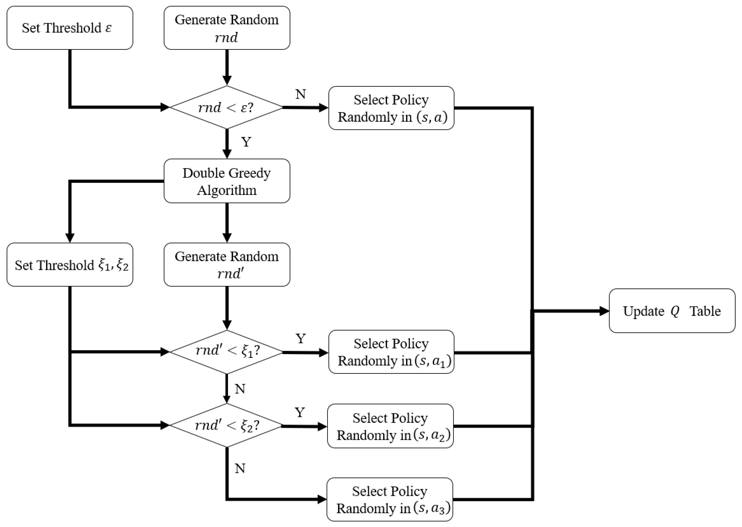
4.2. DGQL (Double-Greedy Reinforcement Learning) Algorithm Based on Information Representation

This section will further improve the Q-Learning algorithm based on the information representation theory and the greedy algorithm. The DGQL framework under the condition of networked UAV radar systems is given.
Q-Learning is a commonly used reinforcement learning method for anti-jamming. The policy selection for Q-Learning is based on the Q table. The Q table has two dimensions: state and action. We consider all parameters of jammer 1, jammer 2 and target as the environment. The algorithm is required to give the corresponding policy of a radar system when given any environment that changes with time, so as to maximize the target information received by the UAV. Specifically, we consider the combination of jamming parameters at each time as the state, and the combination of radar system policies at each time is considered as an action. This process can be modelled as a Markov decision process (MDP). Traditional Q-learning uses tables to store Q values corresponding to each state and action, hence it has two limitations, namely scalability and continuous action. Therefore, deep Q network (DQN) and DDPG (deep deterministic policy gradient) methods were proposed in the reinforcement learning family.
DQN improves the scalability of Q-learning by adopting neural network may generate Q value to avoid tabular representations. However, the learning effect of DQN is related to the memory stored previously in a database. Simulation experiments usually show that DQN has a better learning effect and convergence speed when the correct actions and wrong actions account for half of each in the memory, which is not the case in the model of this paper. DDPG is a reinforcement learning method for continuous action by integrating a deep convolutional neural network as the simulation of policy function and Q function, that is, policy network and Q network, and then use the method of deep learning to train the above neural network. However, fine tuning of parameters in DDPG is important, such as the learning rate of the actor network and critical network, regularization parameters, neural network structure and so on. If the parameters are not adjusted properly, the algorithm convergence behavior is poor.
Therefore, as an initial contribution to adopt reinforcement learning in UAV-networked radar systems, we select Q-learning algorithm of ensured stability. This helps to gain more insights in the system model, problem dimension reduction and performance analysis, rather than devoting to fine-tuning the “black-box” in DQN and DDPG for high state-action parameter dimensions.
Firstly, the algorithm calculates the SIR received by the communication UAV. This is based on the combination of various radar policies and jamming policies according to the network topology. According to the radar working mode, the algorithm judges the calculation method of information, and then stores the R value in reserve. Then the modified Q-Learning algorithm is used to iterate the policy. Considering that the moving position of the communication UAV will cause a large energy loss, if its action is not constrained, it will generate results that are not realistic. Therefore, we further constrain the action selection by the double greedy algorithm.
The greedy algorithm is embedded in the Q-Learning algorithms to allow randomized action selection. It enables the agents to take randomized actions determined by probability distribution rather than Q table. This probability may be controlled by the threshold ε of the greedy algorithm. In our system, most of the energy of the communication UAV is used for motion, which should be controlled. Therefore, a soft constraint is set on the communication UAV that allows 1 or 2 moving steps with a higher probability and only set a low probability for further movement. We set two thresholds ξ 1 , ξ 2 , where 0 < ξ 1 < ξ 2 < 1 . When the communication UAV chooses the action, a random number r n d within the range of [0, 1] is generated. Then it is compared with ξ 1 , ξ 2 to determine the action within three action subsets. If 0 < r n d < ξ 1 , the UAV selects an action in the action subset a 1 which contains one motion step. If ξ 1 < r n d < ξ 2 , the UAV selects within the action subset a 2 containing two motion steps. If ξ 2 < r n d < 1 , the UAV will select the action in action subset a 3 of more than two motion steps.
In this way, the probability of choosing one step, two steps and more than two steps for the communication UAV is ξ 1 , ξ 2 ξ 1 and 1 ξ 2 respectively. The threshold values ξ 1 , ξ 2 may be set according to the specific UAV setups and task requirements. When ξ 2 approaches 1, the motion of the communication UAV is strictly limited to two steps or less. This process is shown in Figure 6 and the pseudo-code of the DGQL is shown in Algorithm 1.
Algorithm 1. Double-Greedy Reinforcement Learning Algorithm
Initialize r table set r ( i , j )
for ( i , j ) in M radar policies and N jamming policies do
  Generate η 1 , η 2 via network topology
  if mode 1 then
    r ( i , j ) = η 1 2 + η 2 2 4
  else if mode 2 then
    r ( i , j ) = 4 ( η 1 + η 2 ) θ 0.5 2
  end if
end for
Set Q ( s , a ) arbitrarily
for each episode do
  Initialize s
  for each step of episode do
   Generate random number r n d and r n d
   if r n d < ε then
    Extract action subset a 1 , a 2 , a 3 from a
    Generate random number r n d
    if 0 r n d < ξ 1 then
     Choose a from ( s , a 1 ) using policy derived from Q
    else if ξ 1 < r n d < ξ 2 then
     Choose a from ( s , a 2 ) using policy derived from Q
    else:
     Choose a from ( s , a 3 ) using policy derived from Q
    end if
   else
    Choose a randomly from s
   end if
   Take action a , observe r , s
    Q ( s , a ) Q ( s , a ) + α [ r + γ max a Q ( s , a ) Q ( s , a ) ]
    s s
   until s is terminal
  end for
end for

5. Simulation Results

5.1. Map Gridding

In order to quantify the location and beam pointing of each agent more conveniently, gridded map modeling is introduced. As shown in Figure 7. The two radar swarms are represented by two discrete points, which can be combined or separated according to the task requirements. The communication UAV is represented by a discrete point, which may move on optional positions in Figure 7. The target consists of a self-defense jammer (jammer 1) and five main scattering points, each of which is numbered. Considering the intensity difference of each scattering on actual targets, the intensity of scattering point 3 is set to be slightly stronger than the other four, and the other four are the same. The target may move within a certain range. Jammer 2 is represented by a fixed point. The azimuth definition is shown in Figure 7.
The tunable parameters of each agent are shown in Table 2. In order to show the angle more clearly, the azimuth is calculated based on the y-axis after 1% deformation of the actual distance. That is to say, 100m of y-axis and 1m of x-axis have the same length in Figure 7.
When the detection requirements are different, the networking topology of radar UAV swarms is different. Considering the problem of radar target location, this section presents two scenarios to verify the effectiveness of the algorithm. In the simulation experiment, the algorithm will generate the corresponding radar multi-parameter policy according to the jamming policy of 10 time steps. In order to control the motion of the communication UAV, we set the greedy coefficient as follows: ξ1 = 0.6, ξ2 = 0.95. Thus, let the communication UAV take one step policy with 60% probability and two steps policy with 35% probability to prevent the communication UAV from consuming excessive energy.

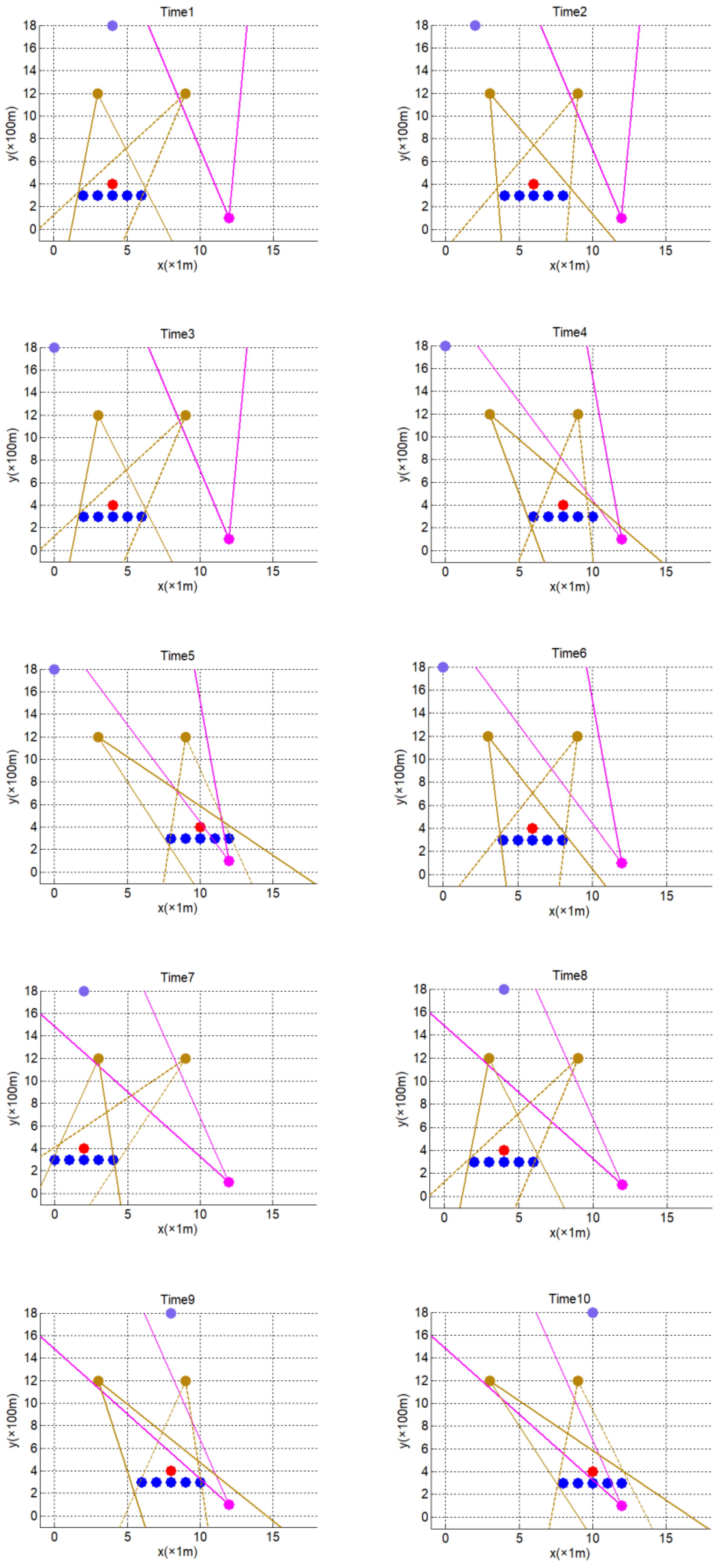
5.2. Collaborative Target Ranging

In this scenario, the radar aggregates the ranging measurements of multiple scattering points for target localization. Range measurement is carried out by using two radar UAV swarms. Two radar UAV swarms are separated from each other, and the target position is determined by the intersection area of beams form by the two swarms. In this scenario, because the distance spanning from the target to the radar is significantly larger than the horizontal size of the target, all scattering points of the target are in the same range profile and may be treated as a whole. Therefore, the radar UAV swarms tend to form wider beams to cover more scattering points, which results in improved SIRs and ranging accuracy.
In the default policy of this group of experiments, the radar transmitting frequency is maintained at 9.4 GHz. The forwarding frequency is always 10.6 GHz. The width of both mainlobe is 50°. The relay position is always at [6,18]. The scanning mode of beam pointing is from right to left, and then from left to right.
In order to display the results more vividly, we give the schematic diagram of time sequence (Figure 8), frequency chart (Figure 9) and normalized information chart (Figure 10). In the schematic diagram of the time sequence, the dot represents the position of each agent and the line represents the mainlobe range of each agent’s 3 dB antenna pattern. Purple represents the communication UAV. Brown represents the radar UAV swarm (the distance between the UAV swarm is very small, so the whole swarm is replaced by a point). Red represents the jammer 1. Blue represents the target scattering point distribution. Pink represents the jammer 2. The legends of the schematic diagram of the time sequence are shown in Figure 11. In order to show the results more clearly, we exclude the base station shown in Figure 7. In order to illustrate the effectiveness of this discrete modelling provided by Q-Learning, we will give the results of normalized information quantity after enlarging the scale of the problem. It should be noted that the maximum and minimum information quantity of each experiment remain unchanged while increasing the scale of the problem. Take the scenario of collaborative target ranging for example, after taking the natural logarithm of each group’s information quantity, the maximum value is 6.2107, and the minimum value is −8.2248, so it is still meaningful to compare the normalized information quantity.
Figure 8 illustrates the policy of UAV swarm radar beam synthesis and the communication UAV motion policy generated. According to the theory in Section 4, the ranging information is only related to SIR, so the beams tend to cover as many scattering echoes as possible. Simulations show that the beam pointing and mainlobe width fits the target area well. As the beam of jammer 2 scans from right to left, the communication UAV makes effective move to avoid jamming, while restricted its motion range to preserve energy as guided by the double greedy algorithm. Figure 9 illustrates the frequency policies adopted by the radar UAV swarms to avoid jamming.
In order to better illustrate the effectiveness of DGQL, we introduce the information of the stochastic policy and the default policy as benchmarks. Stochastic policy refers to the random selection of all radar policies at each time. Default policy refers to a policy choice when the radar UAV swarm does not have any prior information about the target. A common default policy is that the radar keeps the beam scanning back and forth in space, keeps the transmission frequency and mainlobe width unchanged, and does not change the position of the communication UAV (always in the center). Figure 10 shows that DGQL generates significantly more information than stochastic policies and default policies.
The normalized information curve shown in Figure 10 is based on 1125 actions, which is realized by 2.5 × 10⁵ times of iteration. In order to analyze the influence of the number of optional actions on information quantity, Figure 12 shows the normalized information curve when the number of actions is 1680, 2800, 4375, 6125 and 8575, respectively. The legends shown in Figure 12 are the number of actions in each group. Their corresponding iteration times are 3.7 × 10⁵, 6.2 × 10⁵, 9.7 × 10⁵, 13.6 × 10⁵ and 19.0 × 10⁵, respectively. The adjusted actions are the transmitting frequency of the radar UAV swarm, the forwarding frequency of the radar UAV swarm and the mainlobe width of radar UAV swarm. Each parameter keeps uniform step in their own allowable range.
By comparing the curves of 1125 actions, the results show that in this scenario, increasing the number of actions cannot effectively improve the information acquisition ability of radar. This is because even when there are only 1125 actions, the effective policies (refers to the policy that enables the radar to obtain high information quantity) are still included in the action set. The algorithm can generate some of these policies by iterations.
Thus, this proves that if the problem scene can be modeled in a reasonable discrete way and the effective policy can be included in the action set, the computing time can be saved without losing the amount of information obtained by the radar, which is cost-effective in our model.

5.3. Collaborative Scattering Point Localization

In this scenario, the radar needs to locate a strong scattering point on the target. Let radar UAV swarm 1 measure angle and radar UAV swarm 2 measure range, because we assume that only radar UAV swarm 2 has the ability to generate narrow beams of angle measurement. When measuring distance, the target is regarded as a whole, which is the same case in collaborative target ranging. When measuring the angle, the target is regarded as 5 discrete scattering points. The strong scattering points are then located according to distance and angle. The angle measurement adopts a beam scanning method. At this time, two UAV swarms need to be in close positions. In order to highlight strong scattering points, 5 scattering points of the target are set to different intensities. The intensity of scattering point 3 in Figure 7 is slightly stronger than that of the other four scattering points. In this way, the angle measurement is concretized as the angle tracking of a key point on a wide azimuth target by radar UAV swarm 2.
The default policy of this experiment is the same as that of collaborative target ranging, except that the width of two mainlobes are 50 ° and 10 ° , respectively. This is because, for the default policy of angle measuring radar, its mainlobe is relatively narrow.
In particular, since the two radar UAV swarms are relatively close at this time, we use the same point to represent them in Figure 13. At this time, the antenna pattern of UAV swarm 2 shown in Figure 13 does not mean that the beam always points to scattering point 3. It represents the mainlobe width when the beam of UAV swarm 2 sweeps through scattering point 3 instead.
In Figure 13, the mainlobe of the angle measuring UAV swarm (UAV swarm 2) is very narrow, only 5 ° . This is because for the beam scanning method, the narrower the mainlobe width, the larger the angle measuring information. At this point, the policy of the angle measuring UAV swarm no longer pursues the high SIR, but seeks a balance between the SIR and the mainlobe width. In this way, the angle-measuring UAV swarm realizes angle tracking of the key part (scattering point No. 3) of the target.
Figure 14 also proves that the frequency policy of the radar UAV swarm and the communication UAV can still be correctly generated when the ranging and the angle measuring modes coexist. Figure 15 shows the effectiveness of DGQL. In particular, we show the result of the policy based on the reward generated by SIR only. At this time, radar UAV swarm 2 adopts a mainlobe width of 20 ° . Although it covers more scattering points and gets higher SIR. The information quantity is still slightly lower than the DGQL policy. Wide mainlobe policy reduces the accuracy of radar angle measurement, which fully proves the validity of information representation theory. Figure 16 also proves that in the scenario of collaborative scattering point localization, increasing the number of action combinations does not significantly improve the information acquisition ability of the radar.

6. Conclusions

In this paper, a novel Q-Learning based anti-jamming algorithm for networked UAV radar systems is proposed for optimizing the information acquisition capabilities, which is captured by the radar information representation. Due to the payload size and energy constraints of UAVs, the beam synthesis method under low bit phase condition is adopted. Both the angle measurement and range measurement scenarios are constructed to evaluate the effectiveness of the proposed algorithms. Simulation results show that the algorithm may facilitate effective anti-jamming and adapt to different tasks. In this paper, the Q-Learning based algorithm is selected due to its stability and interpretability, while it also discretizes the state variables in space, frequency and antenna beamforming, which may be continuous in general. In our future work, we will consider the reinforcement learning algorithm to generate continuous policies, such as the deep deterministic policy gradient (DDPG).

Author Contributions

Methodology, Q.W.; Supervision, H.W., X.L. and J.P.; Writing—original draft, Q.W.; Writing—review and editing, B.Z.

Funding

This work is funded by the National Natural Science Foundation of China (No. 91648204, No. 61601486), Research Programs of National University of Defense Technology (No. ZDYYJCYJ140601), and State Key Laboratory of High Performance Computing Project Fund (No. 1502-02).

Conflicts of Interest

The authors declare no conflicts of interest.

References

  1. Xing, Q.; Zhu, W.-G.; Jia, X. Intelligent countermeasure design of radar working-modes unknown. In Proceedings of the IEEE International Conference on Signal Processing, Louisville, KY, USA, 6–8 December 2018; IEEE: Piscataway, NJ, USA, 2018. [Google Scholar]
  2. Zhang, J. Study on wideband sparse spectrum waveform for anti-interception and anti-jamming countermeasure. In Proceedings of the CIE International Conference on Radar, Seattle, WA, USA, 8–12 May 2017; IEEE: Piscataway, NJ, USA, 2017. [Google Scholar]
  3. Song, X.; Willett, P.; Zhou, S.; Luh, P.B. The MIMO radar and jammer games. IEEE Trans. Signal Process. 2011, 60, 687–699. [Google Scholar] [CrossRef]
  4. Deligiannis, A.; Lambotharan, S. A Bayesian game theoretic framework for resource allocation in multistatic radar networks. In Proceedings of the 2017 IEEE Radar Conference (RadarConf), Seattle, WA, USA, 8–12 May 2017; IEEE: Piscataway, NJ, USA, 2017. [Google Scholar]
  5. Lan, X.; Li, W.; Wang, X.; Yan, J.; Jiang, M. MIMO radar and target Stackelberg game in the presence of clutter. IEEE Sens. J. 2015, 15, 6912–6920. [Google Scholar] [CrossRef]
  6. Jameel, F.; Wyne, S.; Kaddoum, G.; Duong, T.Q. A comprehensive survey on cooperative relaying and jamming strategies for physical layer security. IEEE Commun. Surv. Tutor. 2018, 21, 2734–2771. [Google Scholar] [CrossRef]
  7. Xiong, J.; Cheng, L.; Ma, D.; Wei, J. Destination-Aided Cooperative Jamming for Dual-Hop Amplify-and-Forward MIMO Untrusted Relay Systems. IEEE Trans. Veh. Technol. 2016, 65, 7274–7284. [Google Scholar] [CrossRef]
  8. Kang, L.; Bo, J.; Hongwei, L.; Siyuan, L. Reinforcement Learning based Anti-jamming Frequency Hopping Strategies Design for Cognitive Radar. In Proceedings of the 2018 IEEE International Conference on Signal Processing, Communications and Computing (ICSPCC), Qingdao, China, 14–16 September 2018; IEEE: Piscataway, NJ, USA, 2018. [Google Scholar]
  9. Wang, Y.; Zhang, T.; Xu, L.; Tian, T.; Kong, L.; Yang, X. Model-free Reinforcement Learning based Multi-stage Smart Noise Jamming. In Proceedings of the 2019 IEEE Radar Conference (RadarConf), Boston, MA, USA, 22–26 April 2019; IEEE: Piscataway, NJ, USA, 2019. [Google Scholar]
  10. Li, H.; Ye, W. A Study on the Influence of Bit Error Ratio against Jamming Signal Ratio under Different Channel Jamming. In Proceedings of the International Symposium on Computational Intelligence & Design, Hangzhou, China, 9–10 December 2017; IEEE: Piscataway, NJ, USA, 2017. [Google Scholar]
  11. Baker, C.J. Intelligence and radar systems. In Proceedings of the Radar Conference 2010, Arlington, VA, USA, 10–14 May 2010. [Google Scholar]
  12. Xingyu, X.; Daoliang, H.; Li, Y.; Xiaoyang, W. Optimal Waveform Design for Smart Jamming Focused on CA-CFAR. In Proceedings of the 2017 International Conference on Computer Network, Electronic and Automation (ICCNEA), Xi’an, China, 23–25 September 2017; IEEE: Piscataway, NJ, USA, 2017. [Google Scholar]
  13. Łabowski, M.; Kaniewski, P. A method of swath calculation for side-looking airborne radar. In Proceedings of the 2018 14th International Conference on Advanced Trends in Radioelecrtronics, Telecommunications and Computer Engineering (TCSET), Lviv, Ukraine, 20–24 February 2018; IEEE: Piscataway, NJ, USA, 2018. [Google Scholar]
  14. Bhattacharya, S.; Başar, T. Game-theoretic analysis of an aerial jamming attack on a UAV communication network. American Control Conference (ACC), Baltimore, MD, USA, 30 June–2 July 2010; IEEE: Piscataway, NJ, USA, 2010. [Google Scholar]
  15. Xiao, L.; Lu, X.; Xu, D.; Tang, Y.; Wang, L.; Zhuang, W. UAV Relay in VANETs Against Smart Jamming with Reinforcement Learning. IEEE Trans. Veh. Technol. 2018, 67, 4087–4097. [Google Scholar] [CrossRef]
  16. Li, H.; Luo, J.; Liu, C. Selfish Bandit based Cognitive Anti-jamming Policy for Aeronautic Swarm network in Presence of Multiple Jammert. IEEE Access 2019, 7, 30234–30243. [Google Scholar] [CrossRef]
  17. Li, Z.; Lu, Y.; Shi, Y.; Wang, Z.; Qiao, W.; Liu, Y. A Dyna-Q-Based Solution for UAV Networks Against Smart Jamming Attacks. Symmetry 2019, 11, 617. [Google Scholar] [CrossRef]
  18. Rahmes, M.; Chester, D.; Clouse, R.; Hunt, J.; Ottoson, T. Cooperative cognitive electronic warfare UAV game modeling for frequency hopping radar. In Unmanned Systems Technology XX; International Society for Optics and Photonics: Orlando, FL, USA, 2018; Volume 10640. [Google Scholar]
  19. Cevik, P.; Kocaman, I.; Akgul, A.S.; Akca, B. The Small and Silent Force Multiplier: A Swarm UAV—Electronic Attack. J. Intell. Robot. Syst. 2013, 70, 595–608. [Google Scholar] [CrossRef]
  20. Xing, Q.; Zhu, W.-G.; Jia, X. Intelligent radar countermeasure based on Q-learning. Syst. Eng. Electron. 2018, 40, 1031–1035. [Google Scholar]
  21. Liu, P.; Liu, Y.; Huang, T.; Lu, Y.; Wang, X. Cognitive Radar Using Reinforcement Learning in Automotive Applications. arXiv 2019, arXiv:1904.10739. [Google Scholar]
  22. You, S.; Diao, M.; Gao, L. Deep reinforcement learning for target searching in cognitive electronic warfare. IEEE Access 2019, 7, 37432–37447. [Google Scholar] [CrossRef]
  23. Wang, L.; Fortunati, S.; Greco, M.S.; Gini, F. Reinforcement learning-based waveform optimization for MIMO multi-target detection. In Proceedings of the 2018 52nd Asilomar Conference on Signals, Systems, and Computers, Pacific Grove, CA, USA, 28–31 October 2018; IEEE: Piscataway, NJ, USA, 2018. [Google Scholar]
  24. Alberge, F. Deep Learning Constellation Design for the AWGN Channel with Additive Radar Interference. IEEE Trans. Commun. 2018, 67, 1413–1423. [Google Scholar] [CrossRef]
  25. Huo, Y.; Tian, Y.; Ma, L.; Cheng, X.; Jing, T. Jamming strategies for physical layer security. IEEE Wirel. Commun. 2017, 25, 148–153. [Google Scholar] [CrossRef]
  26. Cui, T.J. Microwave metamaterials–From passive to digital and programmable controls of electromagnetic waves. J. Opt. 2017, 19, 084004. [Google Scholar] [CrossRef]
  27. Liu, S.; Cui, T.J.; Zhang, L.; Xu, Q.; Wang, Q.; Wan, X.; Gu, J.Q.; Tang, W.X.; Qing, Q.M.; Han, J.G.; et al. Convolution operations on coding metasurface to reach flexible and continuous controls of terahertz beams. Adv. Sci. 2016, 3, 1600156. [Google Scholar] [CrossRef] [PubMed]
  28. Wu, Q.; Cheng, Y.; Li, X.; Wang, H. Beam Synthesis with Low-Bit Reflective Coding Metamaterial Antenna: Theoretical and Experimental Results. Int. J. Antennas Propag. 2018, 2018, 1–9. [Google Scholar] [CrossRef]
  29. Cheng, Y.; Wang, X.; Caelli, T.; Li, X.; Moran, B. On information resolution of radar systems. IEEE Trans. Aerosp. Electron. Syst. 2012, 48, 3084–3102. [Google Scholar] [CrossRef]
  30. Cheng, Y.; Wang, X.; Morelande, M.; Moran, B. Information geometry of target tracking sensor networks. Inf. Fusion 2013, 14, 311–326. [Google Scholar] [CrossRef]
Figure 1. (a) Framework of radar swarm networking system; (b) internal structure of radar unmanned aerial vehicle (UAV) swarm.
Applsci 09 05173 g001aApplsci 09 05173 g001b
Figure 2. Schematic diagram of repetitive coding and convolution methods.
Applsci 09 05173 g002
Figure 3. (a) Antenna pattern for p = 2 and p = 3 (b) Antenna pattern after the two coding modes p = 2 and p = 3 are added.
Applsci 09 05173 g003
Figure 4. Equivalent uniform plane array (UPA) formed by 4 Sub-UAVs.
Applsci 09 05173 g004
Figure 5. Simulation result of 2-D beam synthesis with low-bit coding. (a) Coding scheme (b) 2-D radiation pattern.
Applsci 09 05173 g005
Figure 6. Flow chart of double greedy algorithm.
Applsci 09 05173 g006
Figure 7. Schematic diagram of gridded modeling.
Applsci 09 05173 g007
Figure 8. Schematic diagram of time sequence.
Applsci 09 05173 g008
Figure 9. Frequency chart of collaborative target ranging.
Applsci 09 05173 g009
Figure 10. Normalized information chart of collaborative target ranging.
Applsci 09 05173 g010
Figure 11. Legends of schematic diagram of time sequence.
Applsci 09 05173 g011
Figure 12. Normalized information chart of collaborative target ranging.
Applsci 09 05173 g012
Figure 13. Schematic diagram of time sequence.
Applsci 09 05173 g013
Figure 14. Frequency chart of collaborative scattering point localization.
Applsci 09 05173 g014
Figure 15. Normalized information chart of collaborative scattering point localization.
Applsci 09 05173 g015
Figure 16. Normalized information chart of collaborative scattering point localization.
Applsci 09 05173 g016
Table 1. System parameters.
ParametersVariables
Transmitting Power of Radar Unmanned Aerial Vehicle (UAV) Swarm 1 P R
Target Scattering Coefficient σ 1 , σ 2 , σ 3 , σ 4 , σ 5
Antenna Gain of Radar UAV Swarm 1 for Each Scattering Point G R 1 , G R 2 , G R 3 , G R 4 , G R 5
Transmission Link Path Loss of Radar UAV Swarm 1 L R 1
Forwarding Gain of Radar UAV Swarm 1 F R
Forwarding Link Path Loss of Radar UAV Swarm 1 L R 2
Transmitting Power of Radar UAV Swarm 2 P r
Antenna Gain of Radar UAV Swarm 2 for Each Target Scattering Point G r 1 , G r 2 , G r 3 , G r 4 , G r 5
Transmission Link Path Loss of Radar UAV Swarm 2 L r 1
Forwarding Gain of Radar UAV Swarm 2 F r
Forwarding Link Path Loss of Radar UAV Swarm 2 L r 2
Transmitting Power of Jammer 1 P j 1
Antenna Gain of Jammer 1 G j 1
Path Loss of Jamming Link 1 L j 1
Transmitting Power of Jammer 2 P j 2
Antenna Gain of Jammer 2 G j 2
Path Loss of Jamming Link 2 L j 2
Table 2. Tunable parameters of agents.
ParametersRangeUnit
Transmitting Frequency of Radar UAV Swarm9–9.8GHz
Forwarding Frequency of Radar UAV Swarm10.2–11GHz
Mainlobe Width of Radar UAV Swarm5–70degree
Position of Communication UAV[0, 18], [2, 18], [4, 18], [6, 18], [8, 18], [10, 18], [12, 18][x (1 m),y (100 m)]
Transmitting Frequency of Jammer 19–9.8GHz
Position of Jammer 1[2, 4], [4, 4], [6, 4], [8, 4], [10, 4][x (1 m),y (100 m)]
Transmitting Frequency of Jammer 210.2–11GHz
Beampointing of Jammer 260–83degree

