A Hybrid Mapping Method with Position and Stiffness for Manipulator Teleoperation


Abstract
1. Introduction
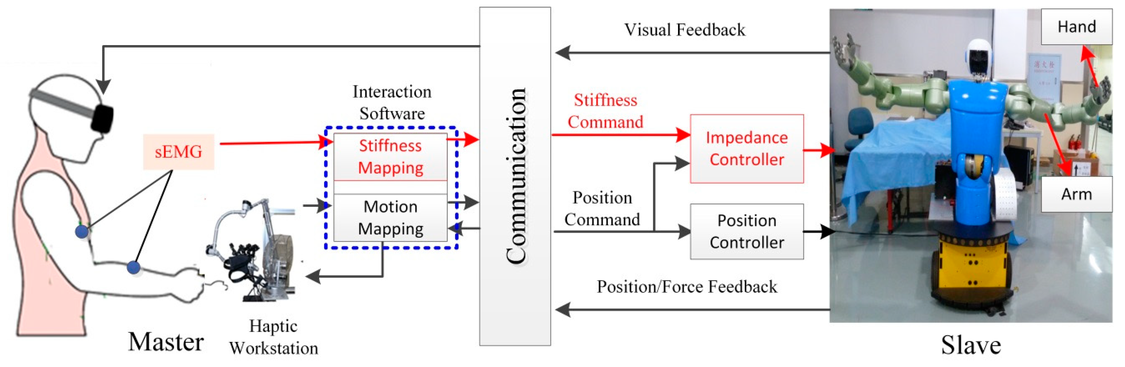
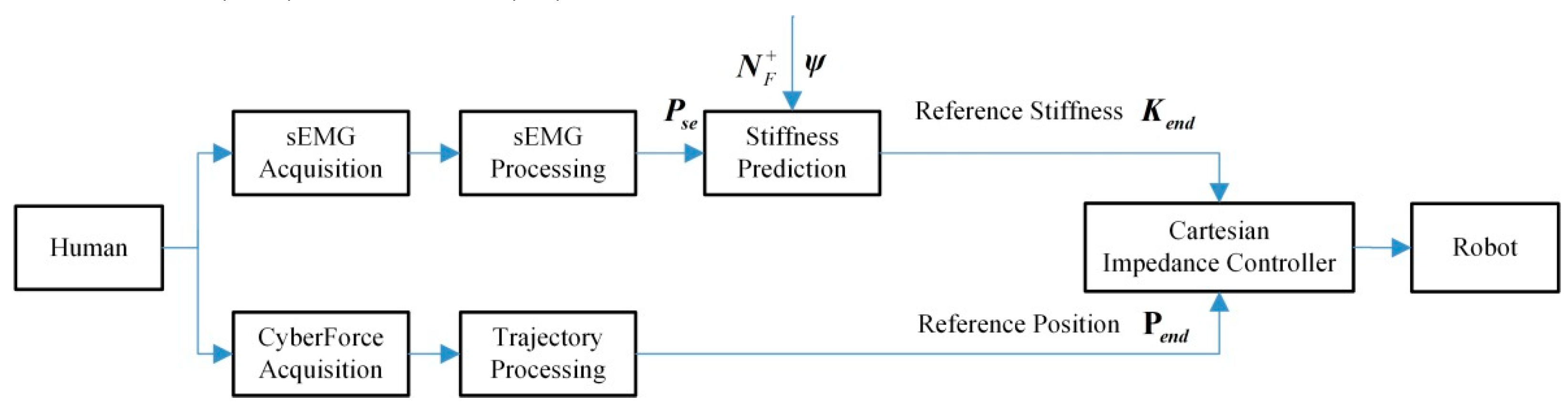
2. System Overview
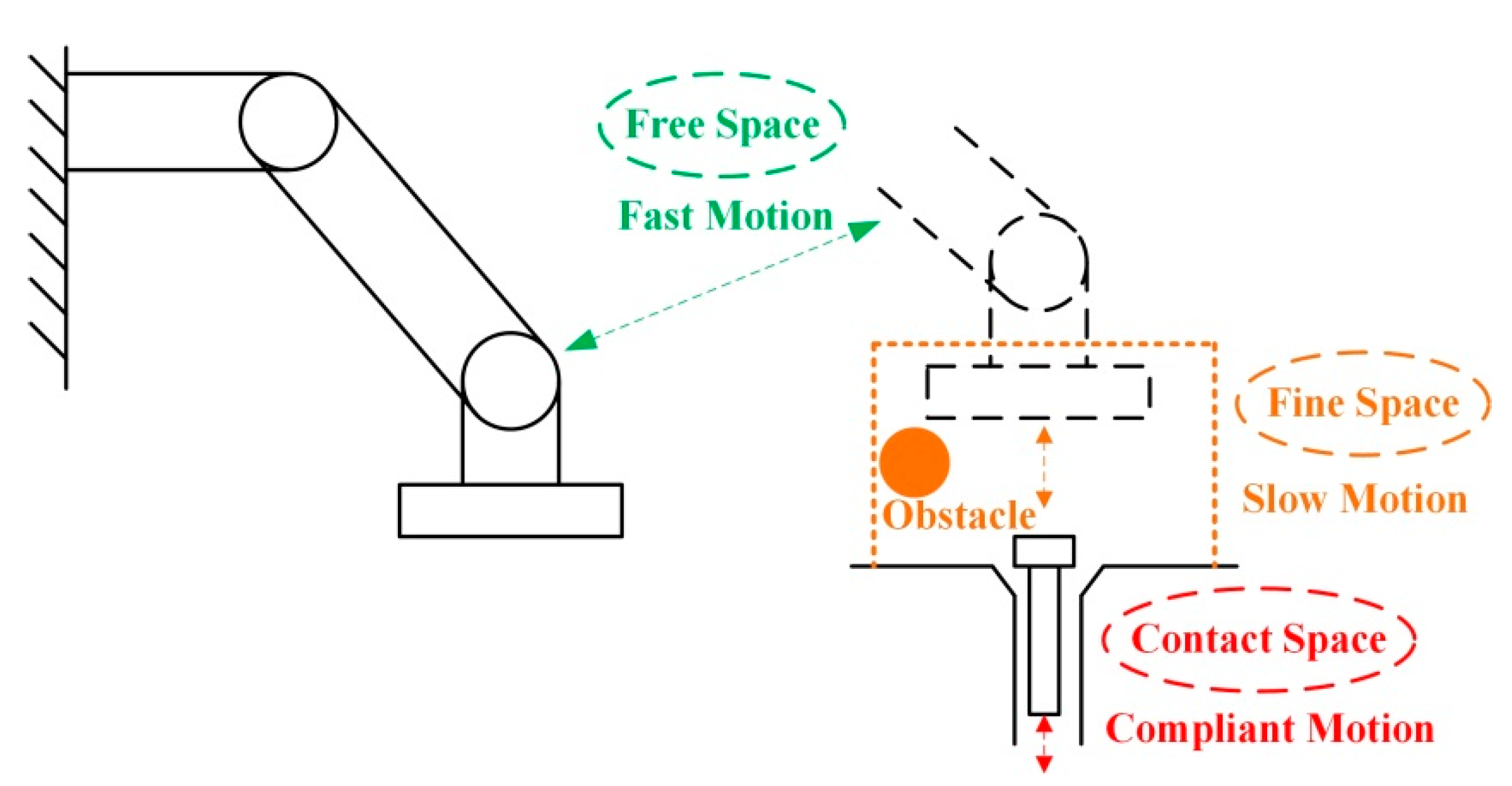
3. Motion Mapping Method for Position Teleoperation
3.1. Fixed Scale Mapping in Free Space
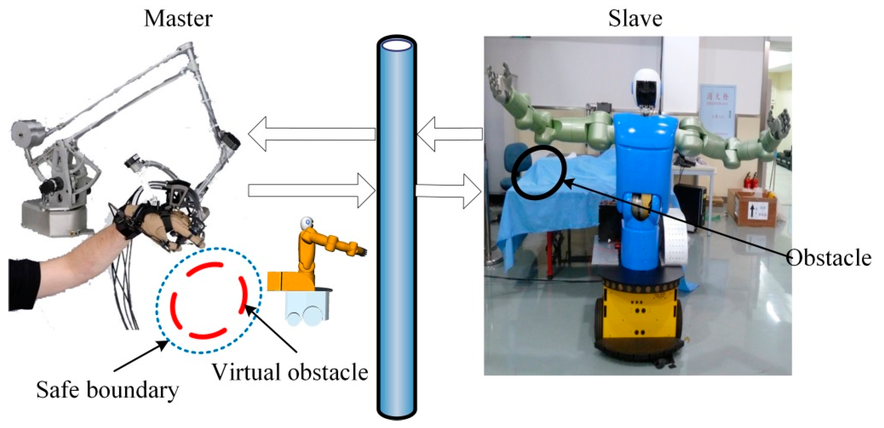
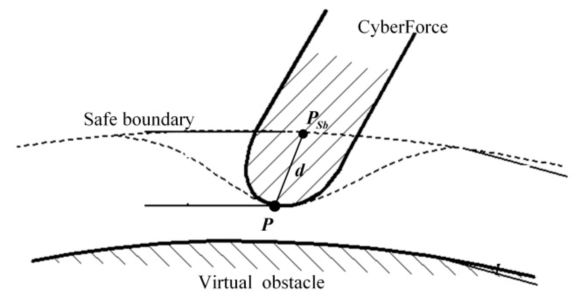
3.2. Virtual Impedance Mapping in Fine Space
4. Stiffness Mapping Method for Compliant Teleoperation
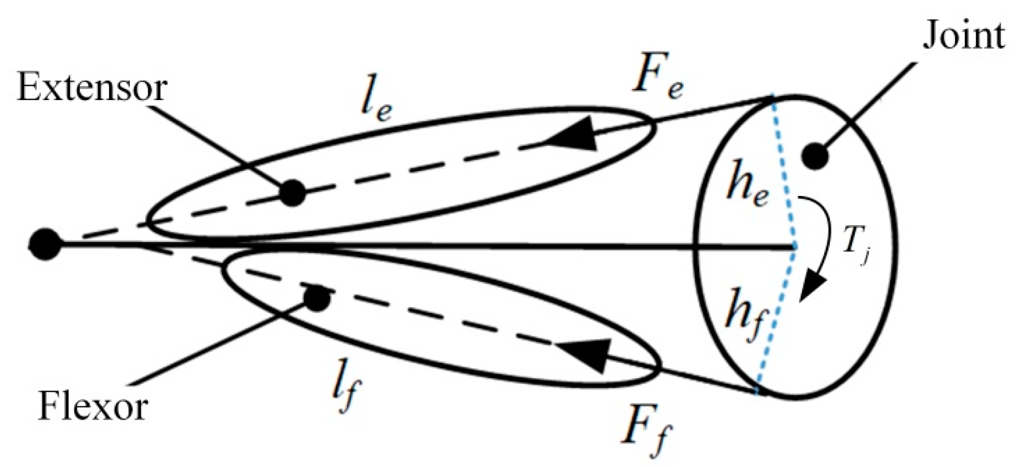
4.1. Stiffness Model at the Human Arm Endpoint
4.2. Stiffness Identification Algorithm at the Human Arm Endpoint
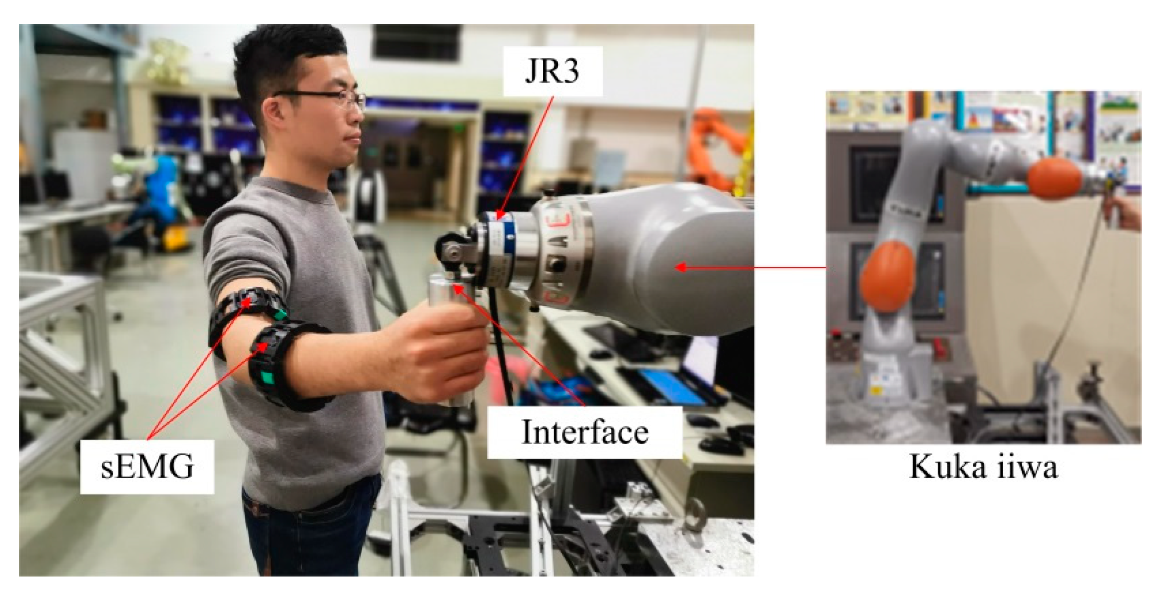
4.3. Stiffness Identification System at the Human Arm Endpoint
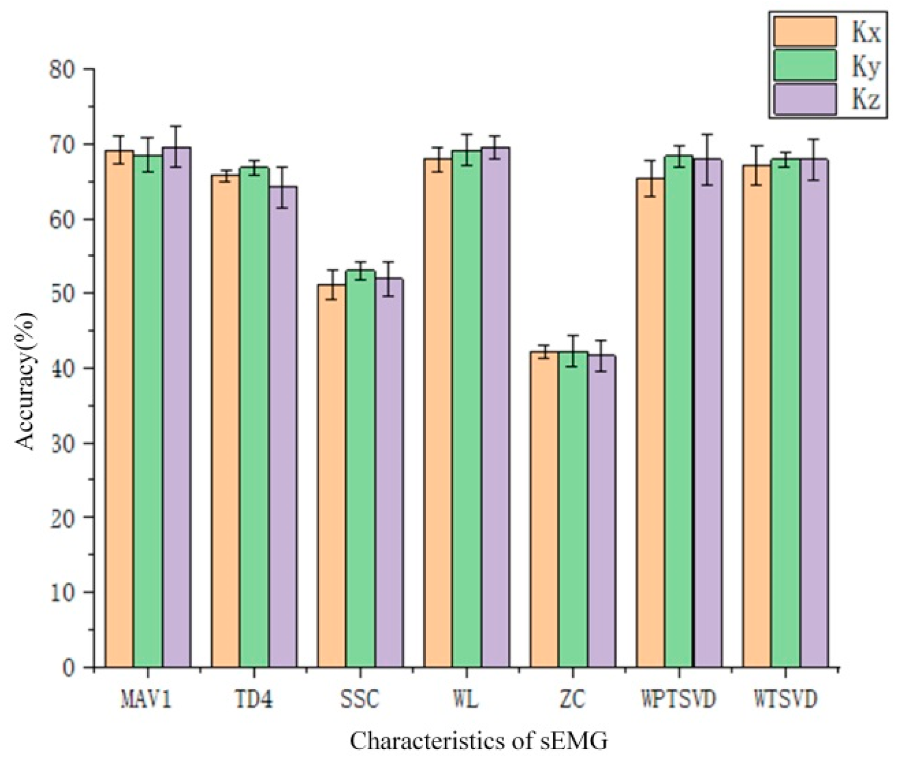
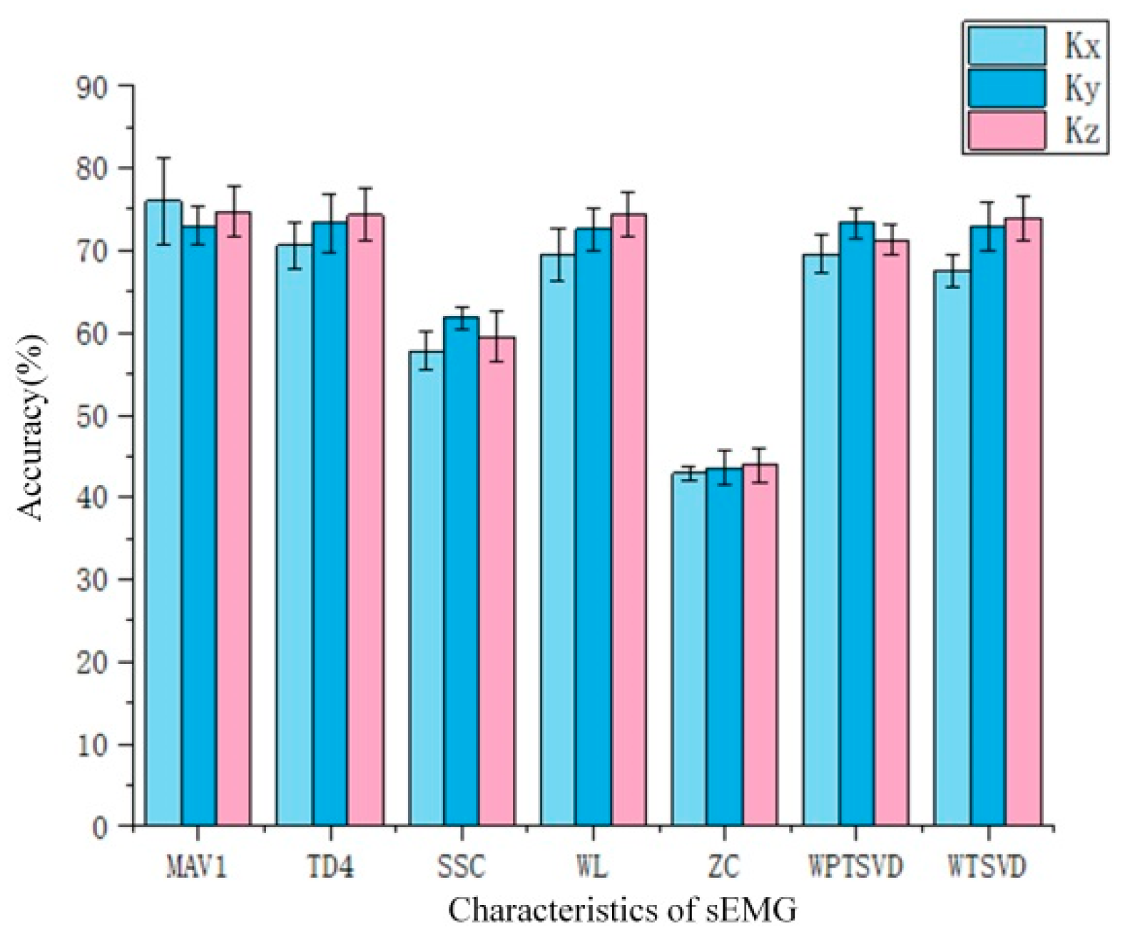
4.3.1. Feature Extraction of sEMG Signals
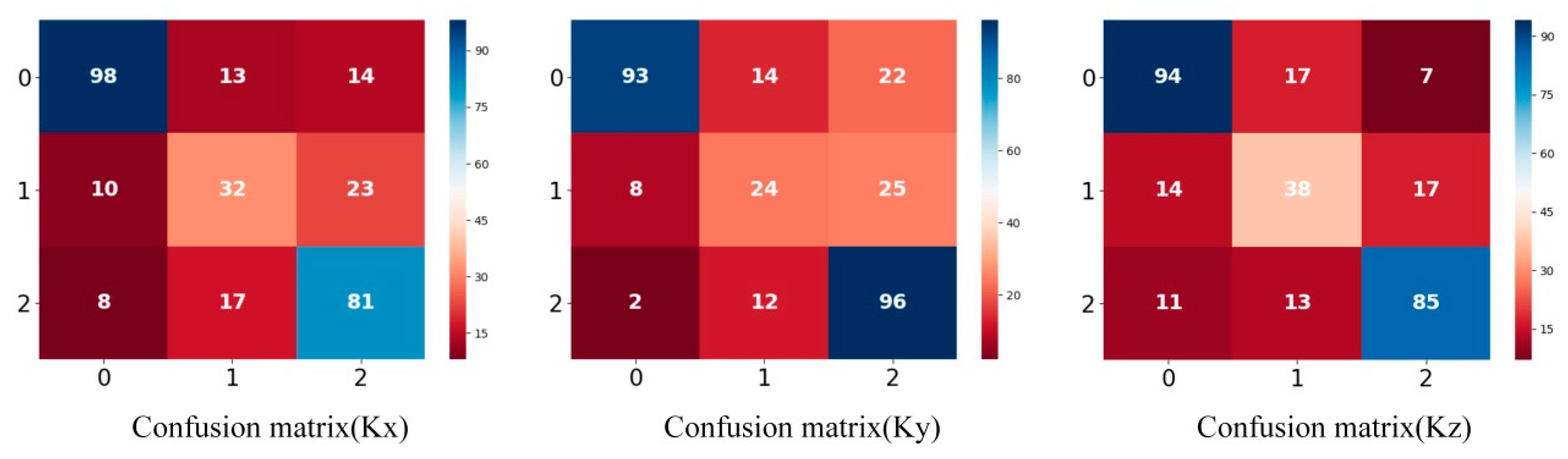
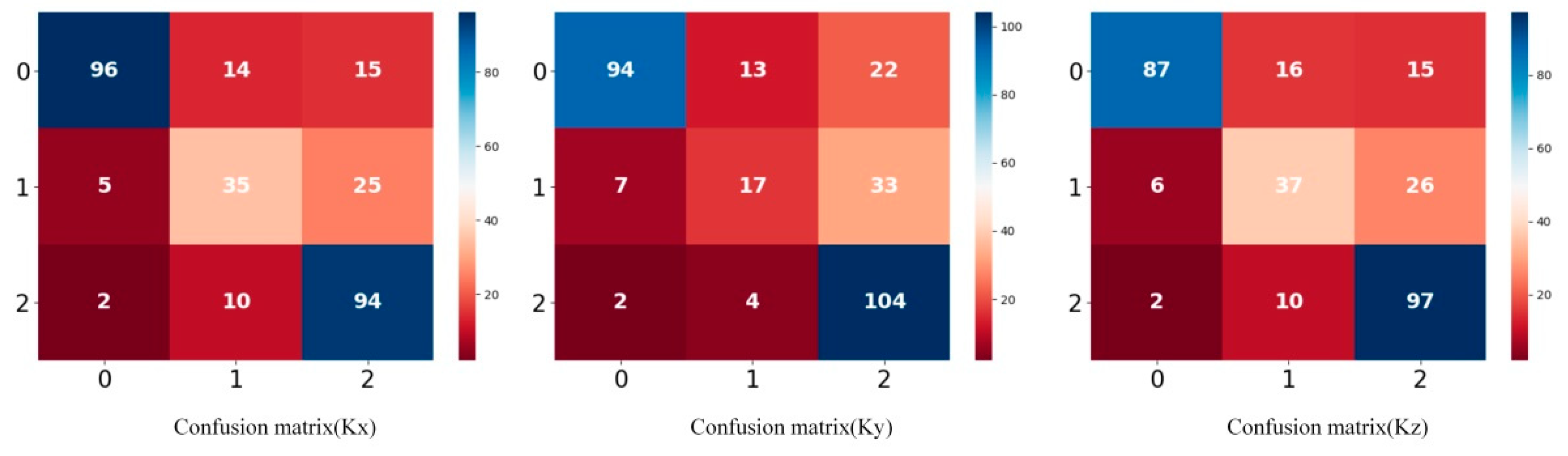
4.3.2. Stiffness Classification at the human arm endpoint
4.4. Stiffness Mapping in Contact Space
5. Results
5.1. Performance Evaluation for Position Teleoperation in Free Space
5.2. Performance Evaluation for Position Teleoperation in Fine Space
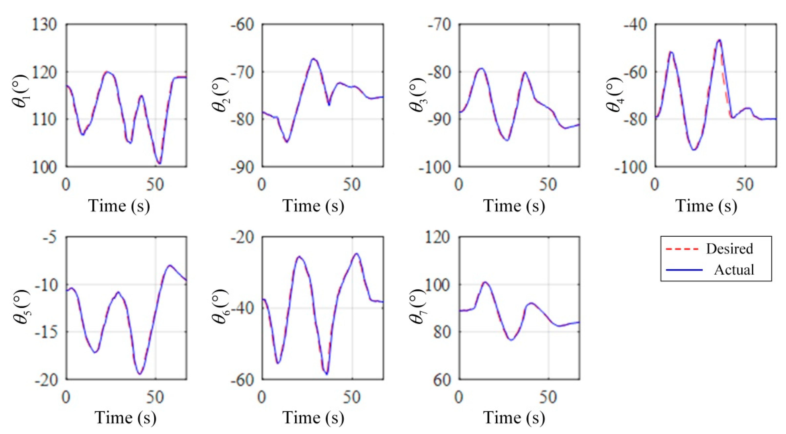
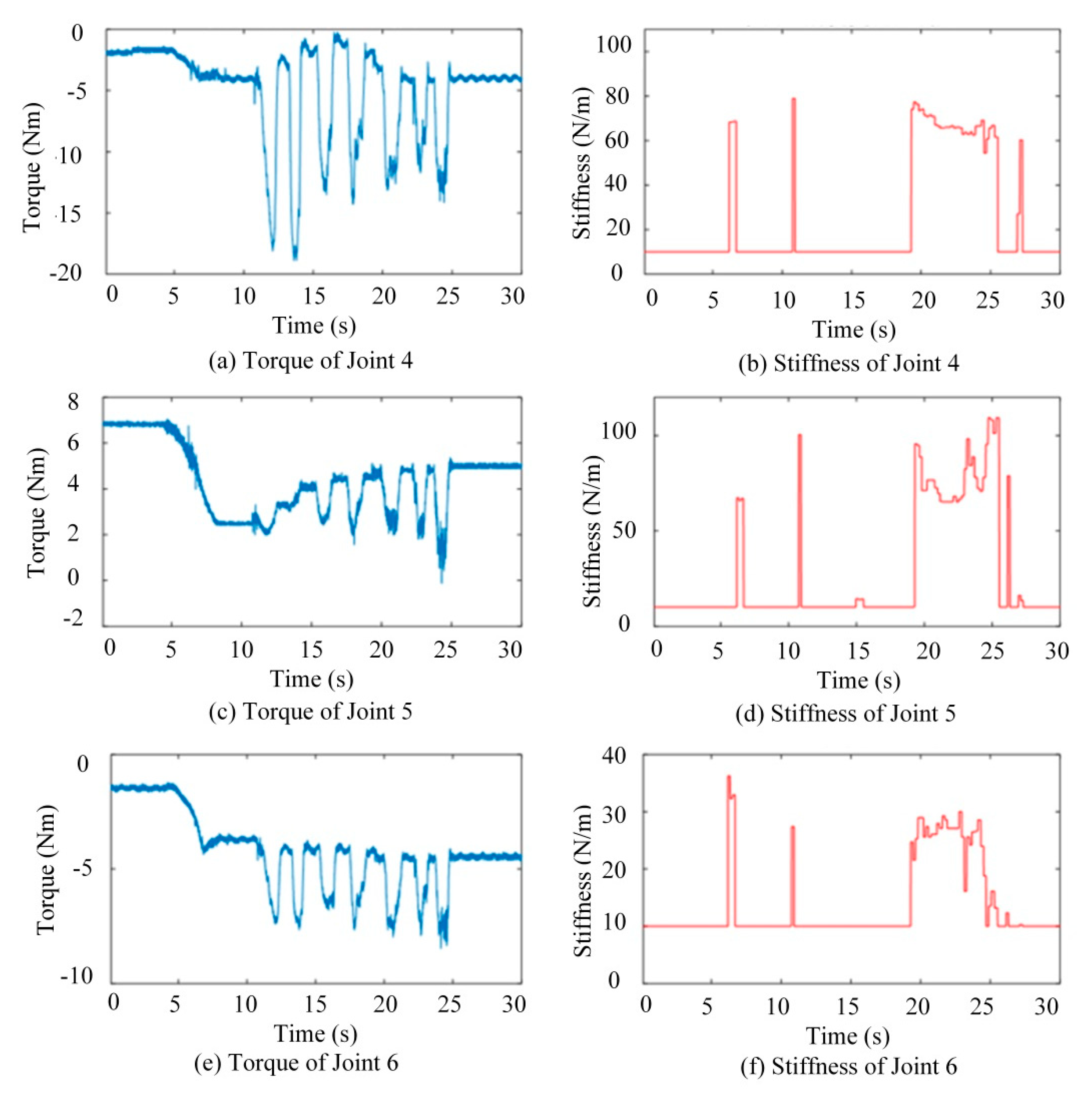
5.3. Performance Evaluation for Compliant Teleoperation in Contact Space
6. Conclusions
Author Contributions
Funding
Conflicts of Interest
References
- Artigas, J.; Hirzinger, G. A brief history of DLR’s space telerobotics and force feedback teleoperation. Acta Polytech. Hung. 2016, 13, 239–249. [Google Scholar]
- Ahlstrom, T.; Curtis, A.; Diftler, M.; Berka, R.; Joyce, C.; Badger, J.; Yayathi, S. Robonaut 2 on the international space station: Status update and preparations for IVA mobility. In Proceedings of the AIAA SPACE Conference and Exposition, San Diego, CA, USA, 10–12 September 2013. [Google Scholar]
- Saltaren, R.; Barroso, A.R.; Yakrangi, O. Robotics for seabed teleoperation: Part-1–conception and practical implementation of a hybrid seabed robot. IEEE Access 2018, 6, 60559–60569. [Google Scholar] [CrossRef]
- Mohareri, O.; Schneider, C.; Salcudean, S. Bimanual telerobotic surgery with asymmetric force feedback: A daVinci surgical system implementation. In Proceedings of the IEEE International Conference on Intelligent Robots and Systems, Chicago, USA, 14–18 September 2014; pp. 4272–4277. [Google Scholar]
- Marturi, N.; Rastegarpanah, A.; Takahashi, C.; Adjigble, M.; Stolkin, R.; Zurek, S.; Kopicki, M.; Talha, M.; Kuo, J.A.; Bekiroglu, Y. Towards advanced robotic manipulation for nuclear decommissioning: A pilot study on tele-operation and autonomy. In Proceedings of the IEEE International Conference on Robotics and Automation for Humanitarian Applications (RAHA), Kerala, India, 18–20 December 2016; pp. 1–8. [Google Scholar]
- Imaida, T.; Yokokohji, Y.; Doi, T.; Oda, M.; Yoshikawa, T. Ground-space bilateral teleoperation of ETS-VII robot arm by direct bilateral coupling under 7-s time delay condition. IEEE Trans. Robot. Autom. 2004, 20, 499–511. [Google Scholar] [CrossRef]
- Niemeyer, G.; Slotine, J.E. Telemanipulation with Time Delays. Int. J. Robot. Res. 2004, 23, 873–890. [Google Scholar] [CrossRef]
- Dolan, J.M.; Friedman, M.B.; Nagurka, M.L. Dynamic and loaded impedance components in the maintenance of human arm posture. IEEE Trans. Syst. Man Cybern. 1993, 23, 698–709. [Google Scholar] [CrossRef]
- Castellini, C.; van der Smagt, P. Surface EMG in advanced hand prothetics. Biol. Cybern. 2009, 100, 35–47. [Google Scholar] [CrossRef] [PubMed]
- Howard, M.; Braun, D.J.; Vijayakumar, S. Constraint-based equilibrium and stiffness control of variable stiffness actuators. In Proceedings of the International Conference on Robotics and Automation, Shanghai, China, 9–13 May 2011; pp. 5554–5560. [Google Scholar]
- Osu, R.; Franklin, D.W.; Kato, H.; Gomi, H.; Domen, K.; Yoshioka, T.; Kawato, M. Short- and long-term changes in joint co-contraction associated with motor learning as revealed from surface EMG. J. Neurophysiol. 2002, 88, 991–1004. [Google Scholar] [CrossRef] [PubMed]
- Hogan, N. Stable execution of contact tasks using impedance control. In Proceedings of the International Conference on Robotics and Automation, Raleigh, NC, USA, 31 March–3 April 1987; pp. 1047–1054. [Google Scholar]
- He, W.; Ouyang, Y.; Hong, J. Vibration Control of a Flexible Robotic Manipulator in the Presence of Input Deadzone. IEEE Trans. Ind. Inform. 2017, 13, 48–59. [Google Scholar] [CrossRef]
- Tsumugiwa, T.; Yokogawa, R.; Hara, K. Variable impedance control based on estimation of human arm stiffness for human-robot cooperative calligraphic task. In Proceedings of the International Conference on Robotics and Automation, Washington, USA, 11–15 May 2002; pp. 644–650. [Google Scholar]
- Erden, M.S.; Billard, A. Hand Impedance Measurements during Interactive Manual Welding with a Robot. IEEE Trans. Robot. 2015, 31, 168–179. [Google Scholar] [CrossRef]
- Walker, D.S.; Salisbury, J.K.; Niemeyer, G. Demonstrating the benefits of variable impedance to telerobotic task execution. In Proceedings of the International Conference on Robotics and Automation, Shanghai, China, 9–13 May 2011; pp. 1348–1353. [Google Scholar]
- Ajoudani, A.; Tsagarakis, N.G.; Bicchi, A. Tele-impedance: Towards transferring human impedance regulation skills to robots. In Proceedings of the International Conference on Robotics and Automation, St. Paul, MN, USA, 14–18 May 2012; pp. 382–388. [Google Scholar]
- Yang, C.; Zeng, C.; Liang, P.; Li, Z.; Li, R.; Su, C. Interface Design of a Physical Human–Robot Interaction System for Human Impedance Adaptive Skill Transfer. IEEE Trans. Autom. Sci. Eng. 2018, 15, 329–340. [Google Scholar] [CrossRef]
- Luo, J.; Yang, C.; Su, H.; Liu, C. A robot learning method with physiological interface for teleoperation systems. Appl. Sci. 2019, 9, 2099. [Google Scholar] [CrossRef]
- Laghi, M.; Ajoudani, A.; Catalano, M.G.; Bicchi, A. Tele-impedance with force feedback under communication time delay. In Proceedings of the IEEE International Conference on Intelligent Robots and Systems, Vancouver, BC, Canada, 24–28 September 2017; pp. 2564–2571. [Google Scholar]
- Haptic Workstation. Available online: http://www.cyberglovesystems.com/haptic-workstation (accessed on 8 September 2019).
- Trigno Avanti Platform. Available online: https://www.delsys.com/trigno/ (accessed on 10 September 2019).
- Cao, B.; Gu, Y.; Sun, K.; Jin, M.; Liu, H. Development of HIT humanoid robot. In Proceedings of the International Conference on Intelligent Robotics and Applications, Wuhan, China, 16–18 August 2017; pp. 286–297. [Google Scholar]
- Li, C.; Jiang, Z.; Wang, Y.; Chen, J.; Liu, H.; Cai, H. Teleoperation of upper-body humanoid robot platform with hybrid motion mapping strategy. In Proceedings of the IEEE International Conference on Real-time Computing and Robotics (RCAR), Kandima, Maldives, 1–5 August 2018; pp. 651–656. [Google Scholar]
- Chen, T.; Guestrin, C. Xgboost: A scalable tree boosting system. In Proceedings of the International Conference on Knowledge Discovery and Data Mining, San Francisco, CA, USA, 13–17 August 2016; pp. 785–794. [Google Scholar]


| Item | Low(Nm) | Middle(Nm) | High(Nm) |
|---|---|---|---|
| 11 | 151 | 400 | |
| 17 | 161 | 387 | |
| 16 | 126 | 416 |
| Item | Value | Item | Value |
|---|---|---|---|
| learning_rate | 0.1/0.1/0.1 | max_depth | 8/10/8 |
| n_estimators | 80/45/85 | min_child_weight | 3/1/0.3 |
| subsample | 1/0.8/0.7 | gamma | 0.4/0.1/0 |
| colsample_bytree | 0.8/0.8/0.8 | reg_lambda | 1.5/1/2 |
© 2019 by the authors. Licensee MDPI, Basel, Switzerland. This article is an open access article distributed under the terms and conditions of the Creative Commons Attribution (CC BY) license (http://creativecommons.org/licenses/by/4.0/).
Share and Cite
Jiang, Z.; Ni, F.; Yang, D.; Li, C.; Yang, F.; Liu, H. A Hybrid Mapping Method with Position and Stiffness for Manipulator Teleoperation. Appl. Sci. 2019, 9, 5005. https://doi.org/10.3390/app9235005
Jiang Z, Ni F, Yang D, Li C, Yang F, Liu H. A Hybrid Mapping Method with Position and Stiffness for Manipulator Teleoperation. Applied Sciences. 2019; 9(23):5005. https://doi.org/10.3390/app9235005
Chicago/Turabian StyleJiang, Zainan, Fenglei Ni, Dapeng Yang, Chongyang Li, Fan Yang, and Hong Liu. 2019. "A Hybrid Mapping Method with Position and Stiffness for Manipulator Teleoperation" Applied Sciences 9, no. 23: 5005. https://doi.org/10.3390/app9235005
APA StyleJiang, Z., Ni, F., Yang, D., Li, C., Yang, F., & Liu, H. (2019). A Hybrid Mapping Method with Position and Stiffness for Manipulator Teleoperation. Applied Sciences, 9(23), 5005. https://doi.org/10.3390/app9235005