Article

Saturated Ground Vibration Analysis Based on a Three-Dimensional Coupled Train-Track-Soil Interaction Model

1
School of Civil Engineering, Southwest Jiaotong University, Chengdu 610031, China
2
Key Laboratory of High-Speed Railway Engineering, Ministry of Education, Southwest Jiaotong University, Chengdu 610031, China
3
School of Engineering, University of Birmingham, Birmingham B15 2TT, UK
*
Author to whom correspondence should be addressed.
Appl. Sci. 2019, 9(23), 4991; https://doi.org/10.3390/app9234991
Submission received: 25 October 2019 / Revised: 14 November 2019 / Accepted: 19 November 2019 / Published: 20 November 2019
(This article belongs to the Special Issue Extreme Sciences and Engineering)

Abstract

:
A novel three-dimensional (3D) coupled train-track-soil interaction model is developed based on the multi-body simulation (MBS) principle and finite element modeling (FEM) theory using LS-DYNA. The novel model is capable of determining the highspeed effects of trains on track and foundation. The soils in this model are treated as saturated media. The wheel-rail dynamic interactions under the track irregularity are developed based on the Hertz contact theory. This model was validated by comparing its numerical results with experimental results obtained from field measurements and a good agreement was established. The one-layered saturated soil model is firstly developed to investigate the vibration responses of pore water pressures, effective and total stresses, and displacements of soils under different train speeds and soil moduli. The multi-layered soils with and without piles are then developed to highlight the influences of multi-layered soils and piles on the ground vibration responses. The effects of water on the train-track dynamic interactions are also presented. The original insight from this study provides a new and better understanding into saturated ground vibration responses in high-speed railway systems using slab tracks in practice. This insight will help track engineers to inspect, maintain, and improve soil conditions effectively, resulting in a seamless railway operation.

1. Introduction

With the rapid development of high-speed rail networks, the ground vibration induced by the dynamic train loads has received increasing attention all over the world [1,2,3]. By the end of 2018, the operating mileage of high-speed rail networks reached 29,000 km in China. These high-speed trains will impart higher dynamic forces in rail infrastructures and result in an elevated vibration level for the ground [4,5,6]. Hence the assessment of ground vibration becomes increasingly essential for the design, operation, and maintenance of railways in practice. Ground vibrations can negatively affect surrounding buildings, tunnels, drainage systems, overhead wiring structures, and so on. Any excessive level of ground vibration can increase both the magnitude and duration of dynamic fatigue cycles, impairing structural integrity and ride comfort, as well as inducing structural damages to infrastructure systems and their components [7].
Numerous researchers have carried out plenty of works related to ground vibration assessments, such as the propagation of Rayleigh waves in the soils [8,9,10], the development of the constitutive model of nonlinear soils with large deformations [11,12,13], the influence of soil properties on ground vibration responses [14,15,16,17], the evaluation of environmental ground vibrations [18,19], and so on. However, most previous numerical studies have merely treated the soil as a single-phase elastic or viscoelastic medium. In real life, a lot of ground soils are saturated because of the presence of underground water, particularly in soft soil areas [20]. When the soil is saturated or of low-permeability, excess pore water pressure will occur during the passage of high-speed trains. The vibration responses such as stresses in soils are thus changed because of the water in the soils.
Terzaghi was the first to propose the effective stress principle for saturated soils. Soil particles and water carry loads in parallel. Biot then developed the famous theory of elastic wave propagation in a porous medium, and the coupled motions of the soil skeleton and interstitial fluid are considered [21]. Based on Biot’s theory, Burke and Kingsbury [22] and Theodorakopoulos [23] proposed an analytical method for two-dimensional (2D) models to investigate the dynamic responses of poroelastic layers under moving loads. Lefeuve-Mesgouez and Mesgouez [24] and Jin [25] further developed the 3D analytical model to study the ground vibration of half-space soils due to the moving loads. Cai et al. [26,27] proposed an integrated analytical train-track-soil model to analyze the vibration responses of saturated soils. However, the analytical method is normally applicable to ideal rail conditions due to some assumptions. The finite element modeling (FEM) method is more suitable for sophisticated railways in practice, due to for example the multi-layered soils with asymmetry loading conditions. Liu et al. [28] and Han et al. [29] developed a 2D numerical model based on the FEM theory to study the vibration responses of saturated soils. The 2.5D models related to the saturated soils are also developed by Gao et al. [20] and Bian et al. [30], but these models are limited in scope due to the plane stress/strain assumptions. Therefore, a 3D FEM model that can consider saturated soils is rather limited. In addition, most previous methods have merely simplified the train loads as moving quasi-static loads and the dynamic wheel-rail interaction under the track irregularity has been ignored, but the dynamic loads play an important role in the train-induced ground vibrations and should be taken into consideration when the ground vibration is investigated [1,2,3,31].
Additionally, although the one-layered ground or half-space soils are easier to carry out for parametric studies and for obtaining the general vibration responses of saturated soils, the multi-layered saturated grounds are actually common in practice [32]. The multi-layered soils will interfere with the wave propagations induced by the dynamic train loads, leading to a different vibration response, particularly when the soils are saturated. Furthermore, the pile-reinforced ground improvement is widely adopted in soft soil regions with high-speed railways since it can significantly reduce both total and differential settlement of soft soils, and the piles will also bring different vibration responses [33,34]. To the author’s knowledge based on our critical review of open literatures, there are no previous studies relating to 3D multi-layered saturated ground vibrations induced by train-track dynamic interactions and the influence of piles on saturated ground vibration responses.
Considering both that saturated soils and wheel-rail contact are easier to be defined in the software LS-DYNA [35,36,37], a novel 3D coupled train-track-soil interaction model is developed in LS-DYNA based on the multi-body simulation (MBS) principle and FEM theory. This model treats the soil as a saturated medium and the wheel-rail dynamic contact induced by track irregularity is simulated based on the Hertz contact theory. The model has been validated against its results with experimental results. The one-layered soil model and the multi-layered soil models with natural and pile-reinforced grounds are developed to investigate the dynamic responses of saturated soils. This study could bring an insightful and better understanding of the saturated ground vibration responses of high-speed railway with slab tracks in practice.

2. Development of the Numerical Model

A novel 3D coupled train-track-soil interaction model is developed in LS-DYNA to investigate the saturated ground vibration responses in high-speed railway with slab tracks. The high-speed train is simulated based on the MBS principle and the slab track and soils are developed based on the FEM theory.

2.1. Modeling of the High-Speed Train and Slab Track

As a commonly operated vehicle on high-speed railway networks in China, the China Railway High-speed (CRH) 380 Electric Multiple Unit (EMU) train is simulated in this model. The vehicle consists of a one-car body, two bogies, four wheelsets, and two stage-suspension systems, as illustrated in Figure 1. The car body, bogies, and wheelsets are simplified as the rigid-bodies with shell and beam elements. These multi-rigid-bodies are connected by the springs and dashpots. As the vertical vibration is the primary excitation to the infrastructures, the vertical degrees of freedom (DOF) of the vehicle are considered in this model. The vehicle has a total of 10 DOF including the vertical and pitch motion of the car body ( Z c ,   β c ), the vertical and pitch motion of the bogies ( Z b i ,   β b i   i = 1 , 2 ), and the vertical motion of the wheelsets ( Z w i   i = 1 , , 4 ).
The China Railway Track System (CRTS) II slab track is adopted in the model. It consists of rail, rail pads, concrete slab, a cement asphalt (CA) mortar layer, and concrete base [38]. The rail is simulated as the Euler beam, which is supported by the discrete springs and dashpots to represent the rail pads. The concrete slab, CA mortar, and concrete base are simulated as solid elements.
The contact between wheel and rail is simulated based on the Hertz contact theory in LS-DYNA [37,39]. The following equation is used to calculate the dynamic wheel-rail contact force:
F = K H × ( Z w Z r δ )
where K H is the vertical stiffness of the wheel-rail contact spring, K H = 1.325 × 10 9 N/m in this study [37]; Z w is the vertical displacement of the wheel; Z r is the vertical displacement of the rail; and δ is the track irregularity. The Germany high-speed low disturbance irregularity is used to excite the wheel-rail contact [37]. The power spectrum density (PSD) function of the track irregularity is calculated as follows:
S v ( Ω ) = A v Ω c 2 ( Ω 2 + Ω r 2 ) ( Ω 2 + Ω c 2 )
where S v ( Ω ) is the vertical power spectral density; A v is the roughness constant ( A v = 4.032 × 10 7   m 2 .   Rad / m ); Ω c and Ω r are the cutoff frequency ( Ω c = 0.8246   rad / m , Ω r = 0.0206   rad / m ); and Ω is the spatial frequency of the irregularity. The PSD function can be transformed into vertical irregularities along the longitudinal distance of the track by means of a time-frequency transformation technique, as shown in Figure 2.
In LS-DYNA, the built-in keywords: *Rail_Track and *Rail_Train are used to define the contact parameters such as the stiffness of the wheel-rail contact spring, the track irregularity, and so on.
The material properties of the CRH380 EMU Train and CRTS II slab track are shown in Table 1. Since most previous studies adopted the static material properties of a slab track despite the fact that the actual loads from high-speed trains onto slab tracks are dynamic excitation [40,41], the dynamic material properties of the CRTS II slab track are used in this model in order to obtain a more realistic vibration response. The stiffness of rail pads is determined by the dynamic value [37] and the moduli of the concrete slab’s elasticity, CA mortar, and concrete base are considered as the strain-rate dependent values.

2.2. Modeling of the Saturated Soils

The saturated soil can have one layer or multi-layers in the simulation model. The one-layered soil model is efficient for carrying out parametric studies and obtaining the general influences of parameters. And the multi-layered soils are actually common in practice. Both one-layered and multi-layered soil models are developed in this study. To avoid repetition, the development of a multi-layered model is elaborated, and the one-layered soil model has the same characteristics.
The multi-layered soils are developed based on a typical cross-section in the Beijing-Shanghai high-speed railway in China [32]. The subgrade consists of three layers: Surface layer, bottom layer, and subgrade body. Furthermore, the ground consists of two layers of clay and three layers of rock.
The subgrade and clay are simulated as solid elements based on the FEM theory in LS-DYNA. In order to improve the calculation efficiency, the rock is not developed in the model, and the fixed boundary is set under the bottom of the second layer of ground instead. Although LS-DYNA provides the infinite boundary options for soils such as Perfectly Matched Layers (PML) and non-reflecting boundary, they are mainly applicable for normal-dry soils without pore waters. When the soils are saturated, the infinite boundary can induce some deformations at the edge of the model in LS-DYNA. Therefore, the normal translational and rotational constraint boundary is still used, but the dimension of the model is set as 100 m × 110 m × 15.5 m to avoid the influence of reflected waves on the vibration responses of soils in the focus-area, which is the soil underneath the slab track, as shown in Figure 3.
In order to simulate the saturated soils, LS-DYNA uses effective stress theory to model materials with pore water pressure. The pore fluid and soil skeleton are assumed to carry loads in parallel. The equation of the saturated soil is shown as follows:
σ t = p + σ e
where σ t is the total stress of the soil; p is the pore water pressure; and σ e is the effective stress of the soil.
The keywords: *Control_Pore_Fluid and *Boundary_Pore_Fluid are used to define the properties of the saturated soils in LS-DYNA [35,36]. Since the water in the soils underneath the slab track is uneasy to dissipate immediately during the passage of the high-speed train, particularly when the soils are of low permeability, the undrained analysis is adopted in the model.
The properties of the water are shown in Table 2. The material properties of multi-layered soils are shown in Table 3. Note that most in-site tests cannot give precise information on the damping of internal soils [43]. In order to minimize the gap between the experimental and numerical dynamic responses of the soil, the Rayleigh damping of soil is usually used in the numerical models [43]. The damping matrix is defined as:
[ C ] = α [ M ] + β [ K ]
where M and K are the mass and stiffness matrix of the whole FEM model, respectively; and α and β are the coefficients. In this model, α = 0 and β = 0.0002 [43].
It is also noted that the piles are widely adopted in ground in high-speed railways [33,34]. The model of pile-reinforced ground is also developed to investigate the influence of piles on saturated ground vibration responses. In the model, the beam element is used to simulate piles to improve the computational efficiency and the shared node method is adopted between the piles and soils. The material properties of the piles are shown in Table 3.

2.3. Numerical Solution

The vehicle is set to travel at a constant speed over the rail after dynamic relaxation. The explicit central difference method is used to integrate the equations of motion of the coupled train-track-soil system by LS-DYNA.

3. Model Validation

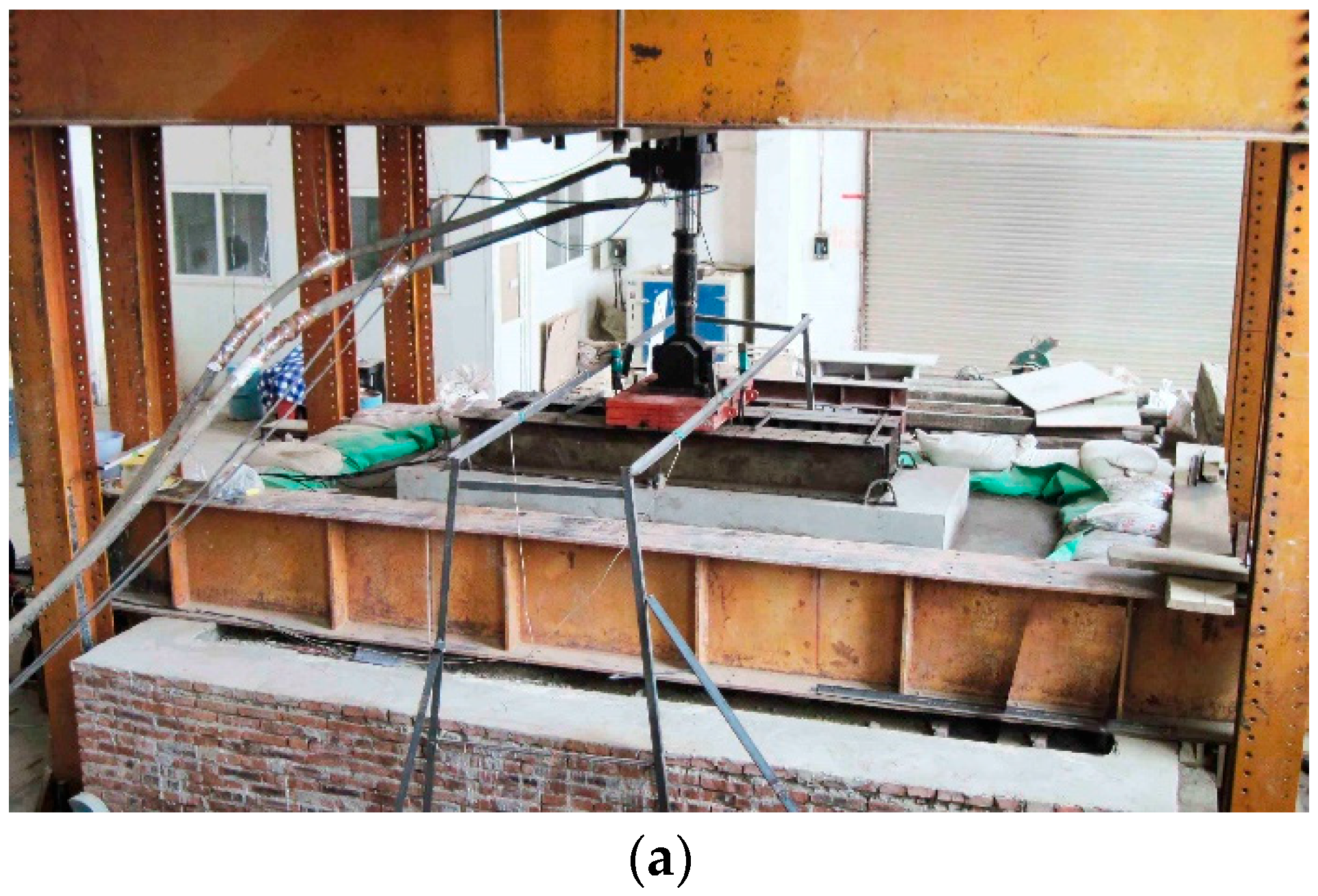
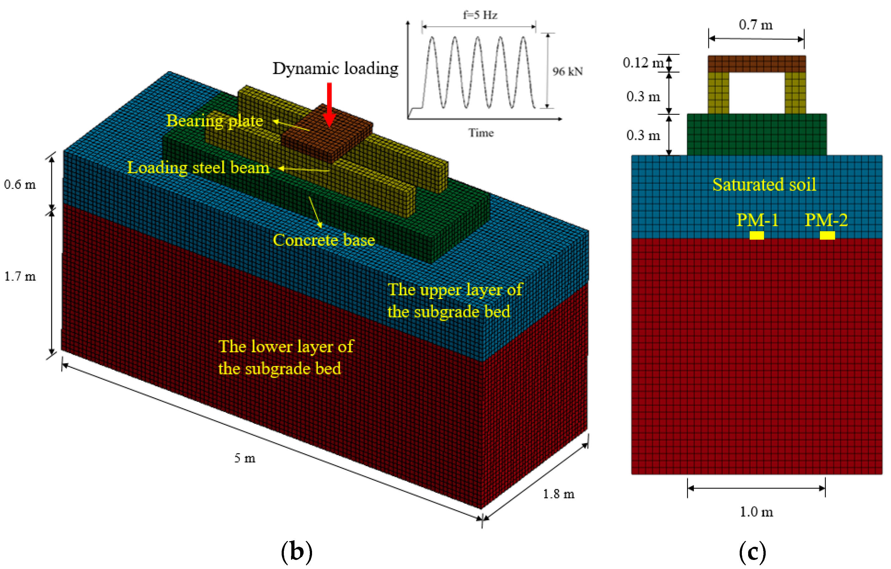
The ground vibration responses and train-track dynamic interactions obtained from the coupled train-track-soil model with dry soils have been validated in [37]. In order to validate the pore water pressure obtained from LS-DYNA, a numerical model with saturated soils is developed based on the lab-test model, in which the time history curves of the pore water pressure of saturated soils are obtained. The test model consists of a bearing plate, loading steel beam, concrete base, the upper layer of subgrade bed, and the lower layer of subgrade bed. The upper layer of subgrade bed is infiltrated with water to make the soil saturated. A waterproof layer between the two layers of soils is used. A dynamic load with an amplitude of 96 kN and a frequency of 5 Hz, is applied to the bearing plate. The details of this lab-test can be found from [44,45,46,47]. The lab-test model and numerical model are shown in Figure 4.
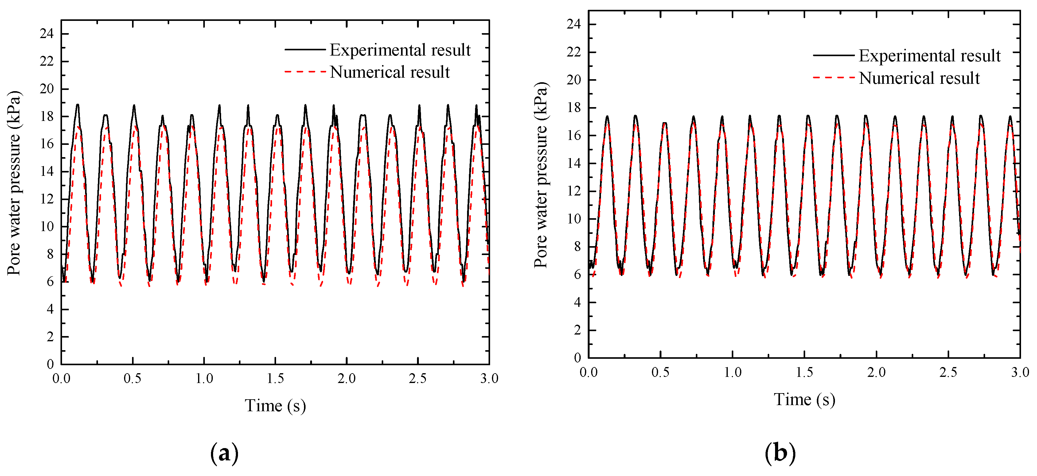
The time history curves of the pore water pressure at PM-1 and PM-2 are illustrated in Figure 5. The simulated curves exhibit a very good agreement with the shapes of experimental results, but the amplitudes show some differences. The maximum and minimum pore water pressures obtained from experimental and numerical results are shown in Table 4. There was less than an 8% difference between experimental and numerical amplitudes in all cases, indicating the pore water pressure obtained from LS-DYNA was reliable in practice. This agreement of the result is thus considered reasonably acceptable.

4. Results

In order to investigate the vibration responses of saturated soils, the one-layered and multi-layered soil models were developed to investigate the pore water pressure, effective stress, total stress, and displacement of saturated soils. In addition, the influence of water on the train-track dynamic interactions is also highlighted.

4.1. Dynamic Responses of the One-Layered Soil

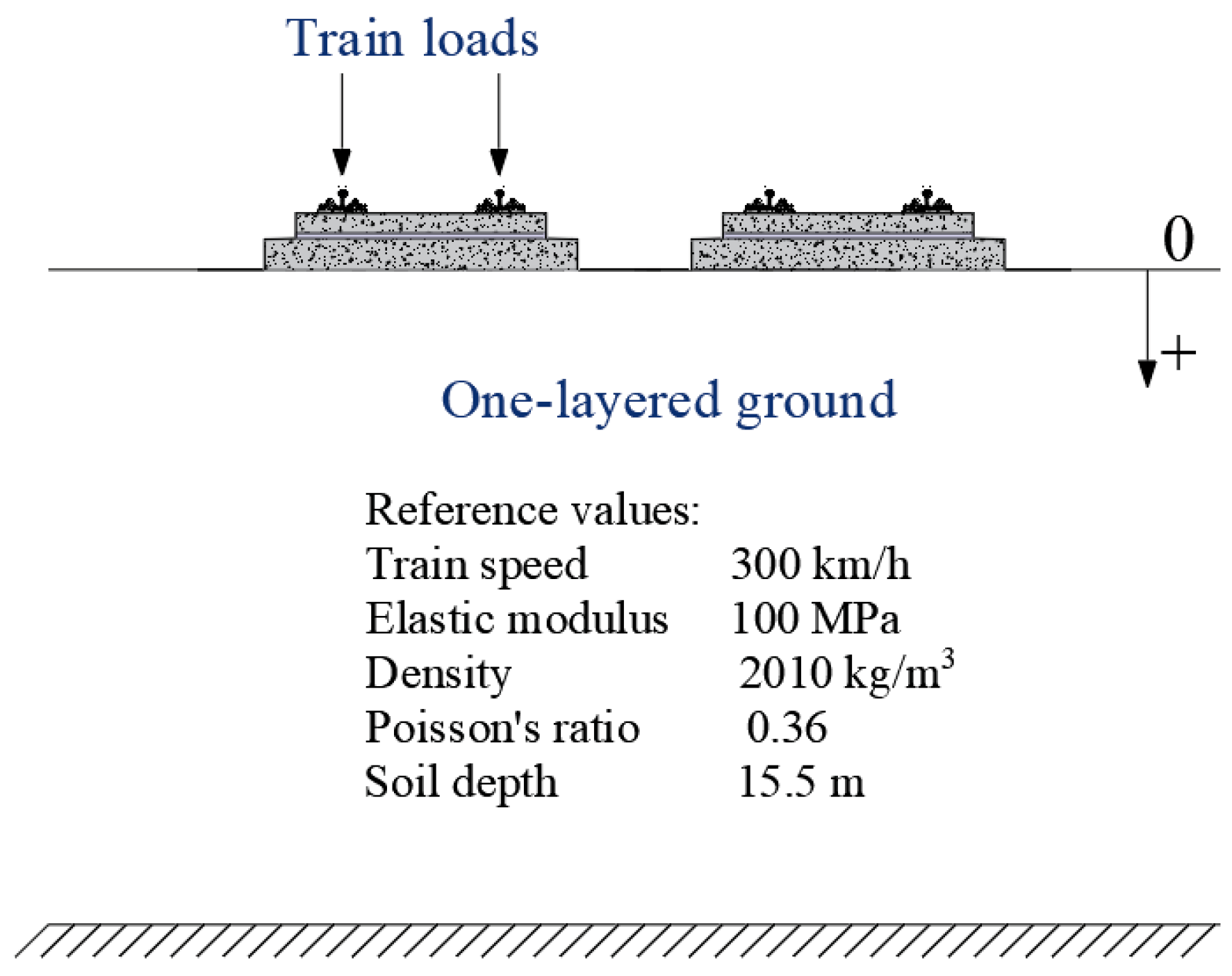
The model with the one-layered ground and the reference values of the parameters are shown in Figure 6. The dynamic responses of saturated soil under train loads are investigated and the influences of train speed and soil elastic modulus on the vibration responses are also studied from the one-layered soil model.

4.1.1. Pore Water Pressure and Effective Stress

The distribution of the pore water pressure at the soil surface is illustrated in Figure 7 when the train travels from the left side to the right side with a speed of 300 km/h. The effect of two bogies of the vehicle on the pore water pressure is evident along with the longitudinal distance. In the lateral direction, the pore water pressure is concentrated within the right track area due to the dynamic train loads. There are also four evident peaks, which are induced by the wheel-rail dynamic contacts.
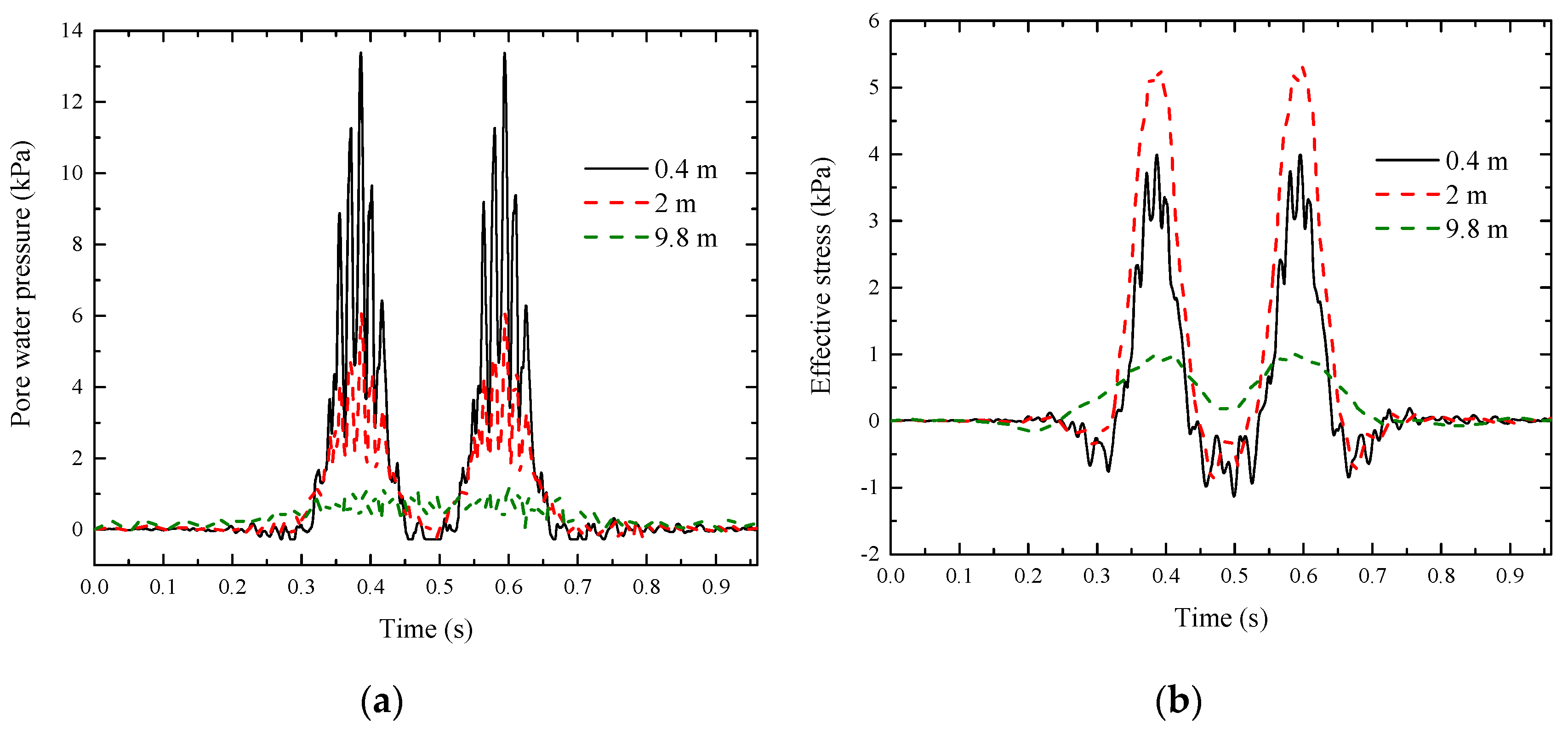
The time history curves of pore water pressure and effective stress of soils underneath the slab track at three soil depths (0.4 m, 2 m, and 9.8 m) are shown in Figure 8. The two noticeable peaks in pore water pressure and effective stress curves were induced by the two bogies of the vehicle. The maximum pore water pressure of the soil decreased with soil depth. However, the maximum effective stress of the soil exhibited a different phenomenon. The effective stress at 2 m was higher than that at 0.4 m, indicating the maximum effective stress did not always decrease along with depth.

4.1.2. Effect of Train Speed

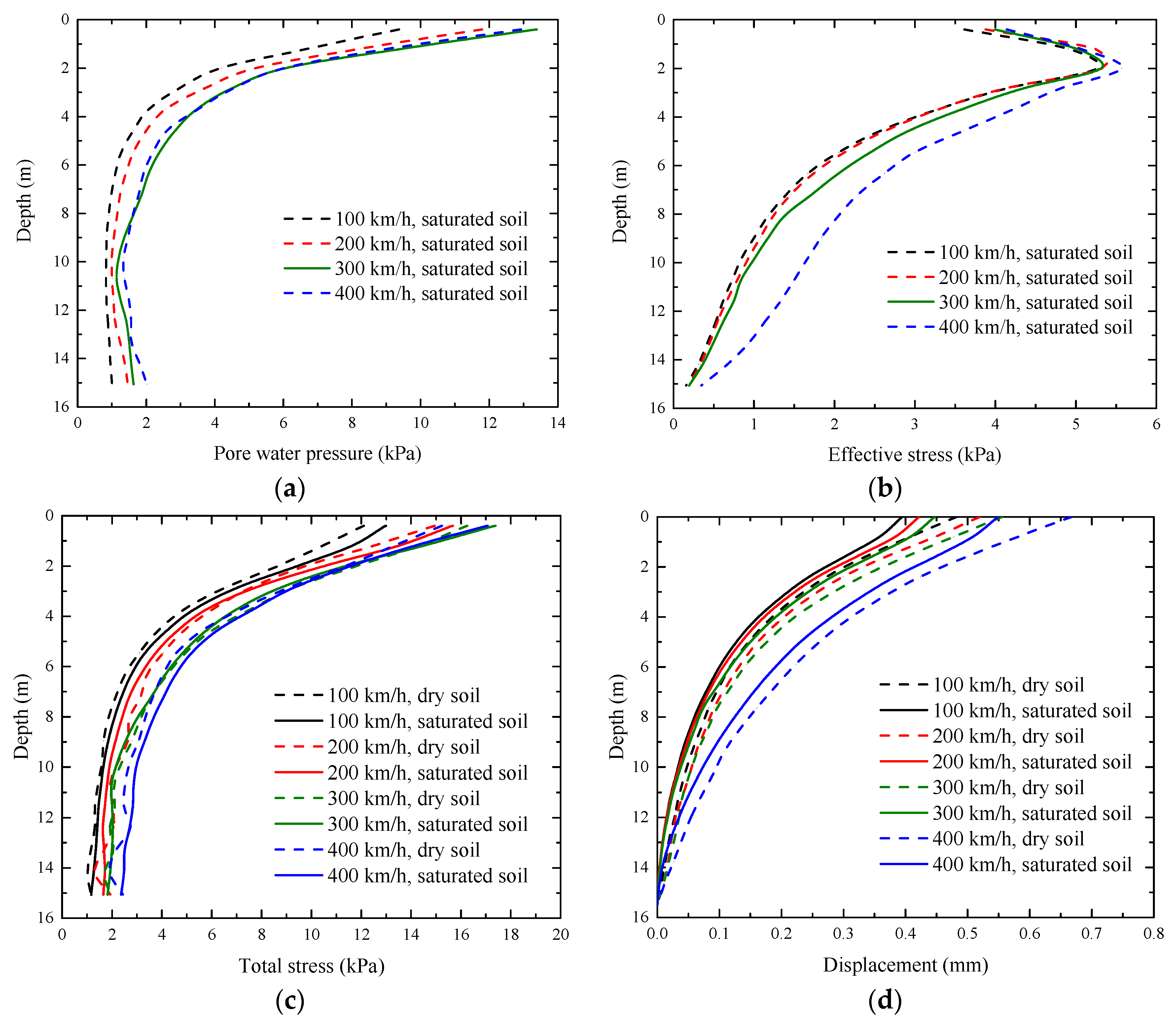
The vibration responses of the saturated and dry soils underneath the slab track are shown in Figure 9 when the train speed increased from 100 km/h to 400 km/h.
The pore water pressure of the saturated soil decreased rapidly at the relatively lower soil depth (<4 m) and kept to a constant value at deeper depths, as shown in Figure 9a. The maximum pore water pressure occurred at the soil surface as the water at the surface was not easy to dissipate immediately. In addition, the train speed had an insignificant influence on the pore water pressure.
Unlike the pore water pressure, the effective stress of the saturated soil exhibited a different tendency with soil depth, as shown in Figure 9b. The maximum effective stress occurred at a depth of around 2 m and then decreased to a relatively small value with depth. Furthermore, the train speed had a small influence on the effective stress. At the soil surface, the effective stress was much lower than the pore water pressure, indicating that the pore water undertook the majority dynamic loads instead of the soil particles. When the depth was lower than 2 m, the soil particles undertook more and more dynamic loads and the effective stress thus increased. When the soil depth was higher than 2 m, the values of pore water pressure was quite close to the values of effective stress, indicating the water and soil particles carried the dynamic loads together at the deeper soil.
The total stress of saturated soil was composed of both pore water pressure and effective stress, while the total stress of dry soil was normal stress. As shown in Figure 9c, the total stresses of saturated soil were a little bit higher than those of dry soil for most cases especially when the depth was lower than 2 m, but the differences were insignificant.
The displacement of saturated soil was lower than that of dry soil, as shown in Figure 9d. The train speed had an evident influence on the displacement. The displacement increased with train speed for both saturated and dry soils.

4.1.3. Effect of Soil Modulus

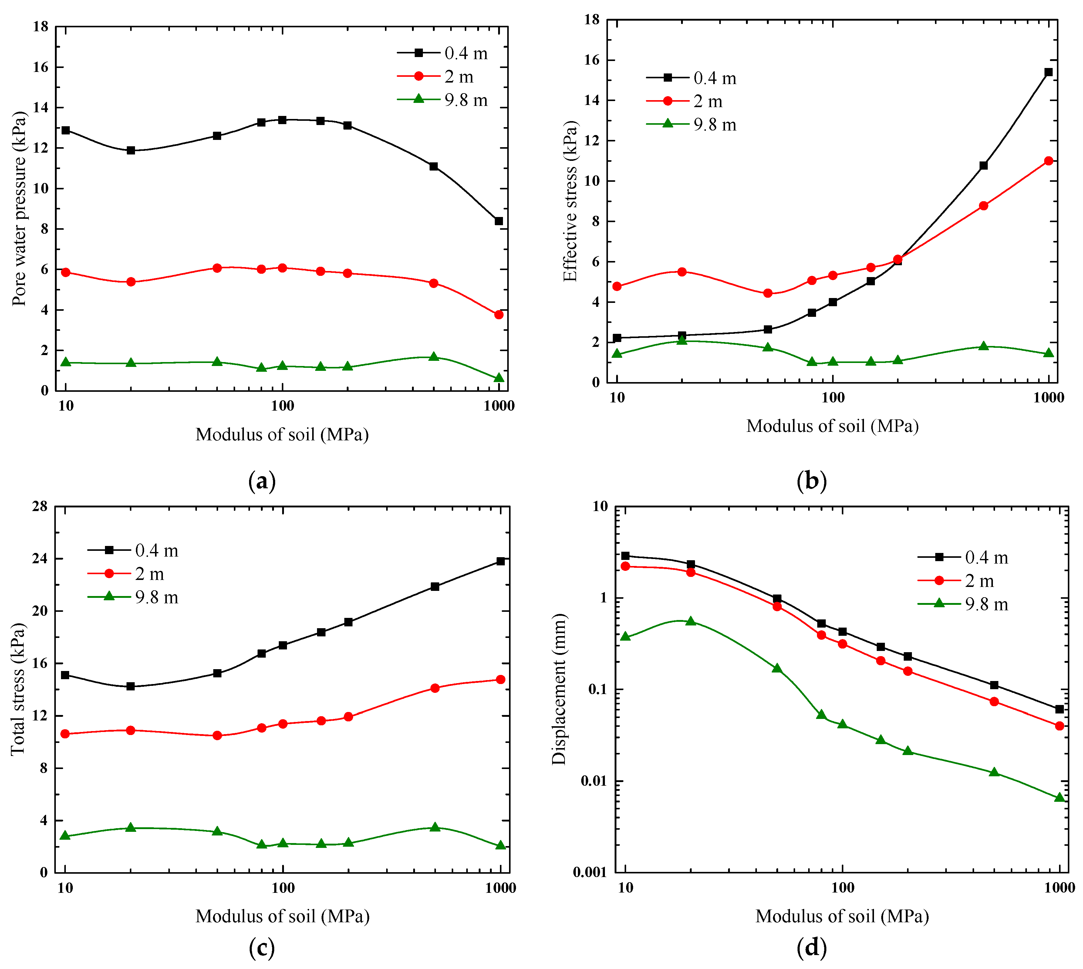
The elastic modulus of the soil increased from 10 MPa (very soft soil) to 1000 MPa (very stiff soil). The vibration responses with soil modulus at three depths are shown in Figure 10. At the surface of the soil (0.4 m), the pore water pressure was much higher than the effective stress when the soil modulus was lower than 200 MPa. In contrast, when the soil became very stiff, the effective stress was much higher than the pore water pressure, indicating that the pore water would carry the majority dynamic loads in soft soils, and the soil particles would undertake more dynamic loads in stiff soils at the soil surface. At 2 m, the pore water pressure had similar amplitudes with effective stress when the soil was soft, and the effective stress was higher than the pore water pressure for stiff soil. As for deeper soils (9.8 m), both the pore water pressure and effective stress did not change much with soil modulus. It is also noted that the effective stress at 0.4 m (surface) was lower than that at 2 m when the soil was soft (≤200 MPa), but was higher than that at 2 m when the soil became stiffer.
The total stresses with soil modulus at three depths are shown in Figure 10c. The values increased with soil modulus at 0.4 m and 2 m, but the modulus had no significant influence on the deeper soils (9.8 m). As for the displacement, it decreased significantly with the soil modulus at the three depths, as shown in Figure 10d.

4.2. Dynamic Responses of the Multi-Layered Soils

The model with multi-layered soils is shown in Figure 11. The subgrade consisted of three layers: Surface layer, bottom layer, and subgrade body. The ground had two layers: First layer and second layer. The model with and without piles are developed in this study. The material properties of the soils and piles are shown in Table 3.
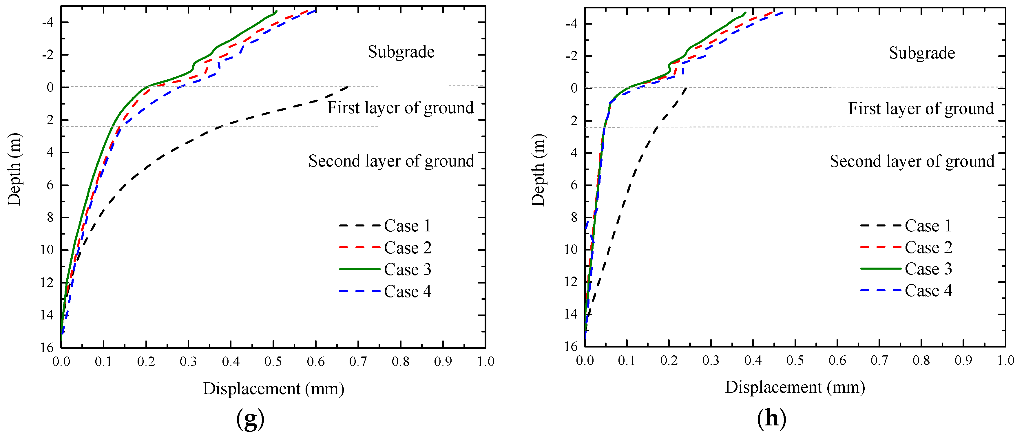
In order to investigate the influence of water on the multi-layered ground vibration responses, four cases are studied, as shown in Table 5. For case 1, the subgrade was not considered and the two-layered ground was saturated. The dry subgrade with three layers and saturated ground with two layers were considered for case 2. Both saturated subgrade and ground were considered for case 3. Furthermore, both dry subgrade and ground were developed for case 4.

4.2.1. Time History Curves

The time history curves of the pore water pressure and total stress at the surface of the first and second layers of ground are shown in Figure 12. The pore water pressure in case 1 was much higher than that in case 2 and case 3 because of the vibration attenuation effect of the subgrade for case 2 and case 3. The pore water pressure of second layer of ground was lower than that of the first layer. The total stress exhibited a similar tendency.
Additionally, the piles had a significant influence on the pore water pressure and total stress. The piles could reduce the amplitudes of pore water pressure and total stress in all cases. It is likely that the dynamic loads were undertaken by the soil particles and pore water in the natural ground, but they were carried by soil particles, pore water, and together with piles in pile-reinforced ground, leading to smaller amplitudes of stresses in the pile-reinforced ground.

4.2.2. Dynamic Responses along with Depth

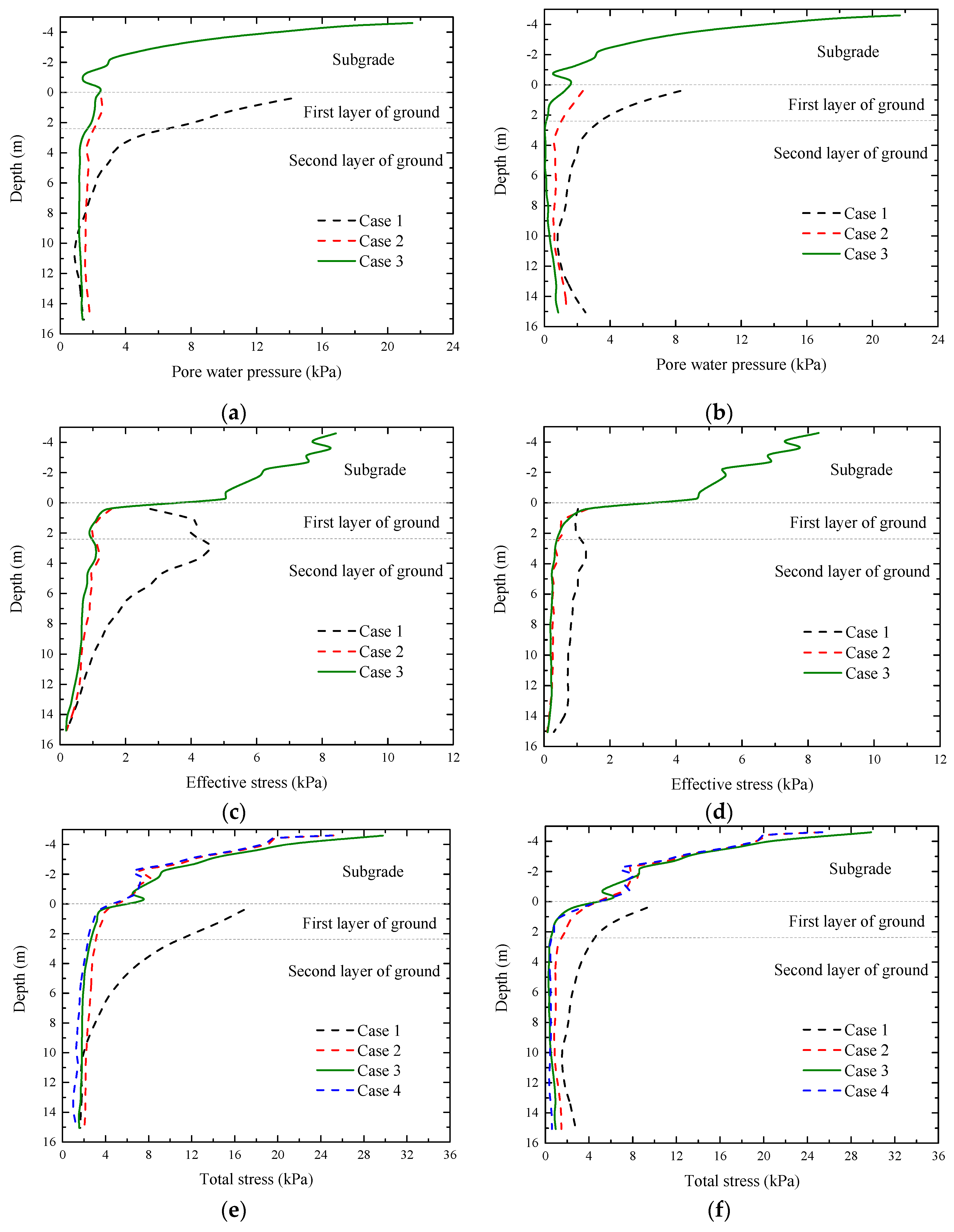
The vibration responses of pore water pressure, effective stress, total stress, and displacement without and with piles are shown in Figure 13. When the piles are not considered, the pore water pressure in case 1 was higher than that in case 2 and case 3 when the depth of ground was lower than 7 m, as shown in Figure 13a. In case 3, the pore water pressure was much higher in subgrade, but it rapidly decreased to a small constant value in the ground. When the piles were taken into consideration, the pore water pressures of ground soils in case 1, case 2, and case 3 became lower than the values in natural ground, as shown in Figure 13a,b.
The effective stress in case 1 still exhibited the tendency of increasing firstly and then decreasing along with depth in natural ground, but when the subgrade is considered in case 2 and case 3, this phenomenon could not be observed. The effective stress in ground had no obvious difference between case 2 and case 3 no matter if the subgrade was dry or saturated. However, when the subgrade and ground were both saturated (case 3), the effective stress decreased rapidly from the subgrade to ground, indicating the subgrade had an excellent vibration attenuation effect. In the pile-reinforced ground, the effective stresses in case 1, case 2, and case 3 were lower than those in natural ground, as shown in Figure 13c,d.
The total stresses in ground in case 2, case 3, and case 4 were much lower than those in case 1. Besides, the total stress exhibited no significant differences between case 2, case 3, and case 4, indicating that the total stress was less influenced by the dry or saturated condition. When the piles were considered, the total stress in subgrade had no obvious difference, but the total stress in ground was reduced, as shown in Figure 13e,f.
The displacement in saturated soils was smaller than that in dry soils by comparing the results from case 2 and case 3, as shown in Figure 13g. Note that the maximum displacement of ground occurred in case 1 because of the lack of subgrade. The piles could also significantly reduce the displacement, as shown in Figure 13h.

4.3. Influences on the Train-Track Interactions

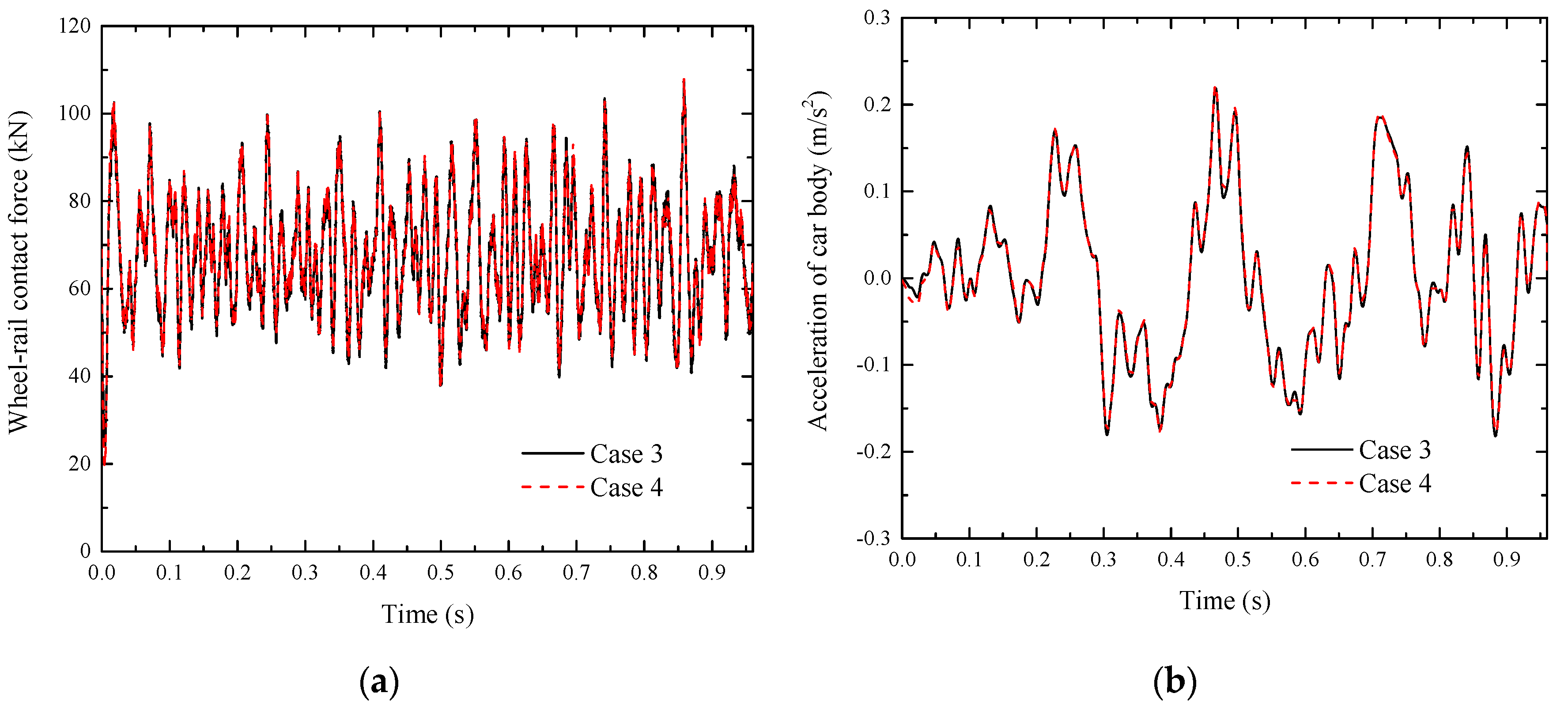
In order to investigate the influence of water on the train-track dynamic interactions, the wheel-rail contact force and the acceleration of the car body were obtained from case 3 and case 4, as shown in Figure 14. There was no noticeable difference between the saturated case (case 3) and dry case (case 4). This was mainly because the undrained water in the soils could not induce a significant change for vibration responses. Therefore the train-track interactions would not change much.

5. Discussion

By comparing the results obtained from this model with other analytical/numerical results, several new phenomena could be observed that is worth highlighting.

5.1. The Tendency of Pore Water Pressure with Depth

In this paper, the maximum pore water pressure occurred at the surface of the soil, as shown in Figure 9a. However, the pore water pressure at the soil surface was equal to 0 kPa in [26] and the maximum pore water pressure along with depth occurred at around 2 m. In [20], when the soil surface was free, the maximum pore water pressure occurred at around 2 m, but when the soil was underneath the elastic medium of the subgrade, the maximum pore water pressure occurred at the soil surface. Note that although the soils were underneath the track in [20], the track simulated as beam elements, indicating the soil surface under the track was free.
Therefore, the different tendency was mainly caused by the different surface conditions of the soils in real conditions. In [26], the soil surface was also free, so the maximum pore water pressure occurred at around 2 m as the water at the surface could be quickly drained. In this paper, the soil was underneath the slab track, which was simulated as a solid elastic medium. The soil surface was not free and the water at the soil surface was not easy to immediately dissipate. Therefore the maximum pore water pressure occurred at the soil surface.

5.2. The Total Stresses of Saturated and Dry Soils

In this paper, the total stresses of saturated soils were a little bit higher than those of dry soils, as shown in Figure 9c. A similar phenomenon can be observed in [46]. However, the difference is insignificant, indicating that the undrained water in the soils would not induce a pronounced difference for the stresses.

5.3. The Displacements of Saturated and Dry Soils

The displacements of saturated soil were lower than those of dry soil for the one-layered ground, as shown in Figure 9d. It is likely that the dynamic loads were undertaken by soil particles and pore water for saturated soil, but for dry soil, they were only carried by soil particles, resulting in a higher displacement. In [29], the displacements of saturated soils were higher than those of dry soils. This is because the water in this study dissipated and the soil could be compressed easily after the drainage of water.
In addition, several studies show that the displacement of saturated/dry soils also related to the critical speed [20,25,48,49]. It is noted that the critical speed of the high-speed railway with slab tracks was quite high (440 km/h for multi-layered ground), and the relationship between critical speed and the displacements of saturated/dry soils needs to be further studied in the future.

6. Conclusions

Most previous studies related to saturated soils have just simplified the train loads as moving quasi-static loads despite the fact that the dynamic wheel-rail contact has a great influence on the vibration responses in reality. In addition, the numerical models adopted in most previous studies are based on 2D or 2.5D models, which actually yield a serious limitation in scope due to plane stress/strain assumptions. A novel 3D coupled train-track-soil interaction model, which considers the wheel-rail dynamic contact as well as the saturated soils, was thus developed based on the MBS principle and FEM theory in LS-DYNA. The model was validated against the experimental results obtained from the field measurements. Based on the dynamic responses of the saturated soils, the following novel insights could be drawn:
  • In the one-layered ground, the maximum pore water pressure occurred at the soil surface and decreased along with soil depth. However, the maximum effective stress occurred at a depth of around 2 m. The total stress exhibited no evident difference between saturated and dry soils, but the displacement of saturated soils was smaller than that of dry soils;
  • When the soil was quite soft, the pore water would carry the majority dynamic loads instead of the soil particles. In contrast, the soil particles would undertake more dynamic loads when the modulus of soils increased;
  • The subgrade exhibited a significant influence on the vibration responses of saturated soils in the multi-layered soils model. The subgrade could reduce the amplitudes of pore water pressure, effective stress, total stress, and displacement of soils. The pile-reinforced ground had lower amplitudes of vibration responses compared with the natural ground;
  • The undrained pore water had an insignificant influence on the train-track dynamic interactions including the wheel-rail contact force and acceleration of the car body.

Author Contributions

Conceptualization, T.L., Q.S., and S.K.; methodology, T.L. and S.K.; software, T.L. and S.K.; validation, T.L., Q.S. and S.K.; formal analysis, T.L.; investigation, T.L., Q.S., and S.K.; resources, Q.S. and S.K.; data curation, T.L.; writing—original draft preparation, T.L.; writing—review and editing, S.K.; visualization, T.L.; supervision, Q.S. and S.K.; project administration, Q.S. and S.K.; funding acquisition, Q.S. and S.K.

Funding

This research was supported by the Key Research Development Program of China (No. 2016YFC0802203-2, No. 2016YFC0802203-3). The APC is sponsored by the University of Birmingham’s Open Access Fund.

Acknowledgments

The authors would like to acknowledge the China Scholarship Council for the financial support. The authors sincerely thank the European Commission for H2020-MSCA-RISE Project No. 691135 “RISEN: Rail Infrastructure Systems Engineering Network,” which enables a global research network that tackles the grand challenge in railway infrastructure resilience and advanced sensing under extreme conditions (www.risen2rail.eu) [7].

Conflicts of Interest

The authors declare no conflict of interest.

References

  1. Connolly, D.P.; Kouroussis, G.; Laghrouche, O.; Ho, C.L.; Forde, M.C. Benchmarking railway vibrations—Track, vehicle, ground and building effects. Constr. Build. Mater. 2015, 92, 64–81. [Google Scholar] [CrossRef]
  2. Kouroussis, G.; Connolly, D.P.; Verlinden, O. Railway-induced ground vibrations—A review of vehicle effects. Int. J. Rail Transp. 2014, 2, 69–110. [Google Scholar] [CrossRef]
  3. Thompson, D.J.; Kouroussis, G.; Ntotsios, E. Modelling, simulation and evaluation of ground vibration caused by rail vehicles. Veh. Syst. Dyn. 2019, 57, 936–983. [Google Scholar] [CrossRef]
  4. Kaewunruen, S.; Martin, V.J.S. Life cycle assessment of railway ground-borne noise and vibration mitigation methods using geosynthetics, metamaterials and ground improvement. Sustainability 2018, 10, 3753. [Google Scholar] [CrossRef]
  5. Li, T.; Su, Q.; Shao, K.; Liu, J. Numerical Analysis of Vibration Responses in High-Speed Railways considering Mud Pumping Defect. Shock Vib. 2019, 2019, 9707909. [Google Scholar] [CrossRef]
  6. Kaewunruen, S.; Wang, Y.; Ngamkhanong, C. Derailment-resistant performance of modular composite rail track slabs. Eng. Struct. 2018, 160, 1–11. [Google Scholar] [CrossRef]
  7. Kaewunruen, S.; Sussman, J.M.; Matsumoto, A. Grand challenges in transportation and transit systems. Front. Built Environ. 2016, 2, 4. [Google Scholar] [CrossRef]
  8. Sheng, X.; Jones, C.; Thompson, D. A theoretical study on the influence of the track on train-induced ground vibration. J. Sound Vib. 2004, 272, 909–936. [Google Scholar] [CrossRef]
  9. Hall, L. Simulations and analyses of train-induced ground vibrations in finite element models. Soil Dyn. Earthq. Eng. 2003, 23, 403–413. [Google Scholar] [CrossRef]
  10. Krylov, V.V.; Dawson, A.; Heelis, M.; Collop, A. Rail movement and ground waves caused by high-speed trains approaching track-soil critical velocities. Proc. Inst. Mech. Eng. F J. Rail Rapid Transit 2000, 214, 107–116. [Google Scholar] [CrossRef]
  11. Dong, K.; Connolly, D.P.; Laghrouche, O.; Woodward, P.; Costa, P.A. Non-linear soil behaviour on high speed rail lines. Comput. Geotech. 2019, 112, 302–318. [Google Scholar] [CrossRef]
  12. Shih, J.Y.; Thompson, D.J.; Zervos, A. The influence of soil nonlinear properties on the track/ground vibration induced by trains running on soft ground. Transp. Geotech. 2017, 11, 1–16. [Google Scholar] [CrossRef]
  13. Costa, P.A.; Calçada, R.; Cardoso, A.S.; Bodare, A. Influence of soil non-linearity on the dynamic response of high-speed railway tracks. Soil Dyn. Earthq. Eng. 2010, 30, 221–235. [Google Scholar] [CrossRef]
  14. Kouroussis, G.; Verlinden, O.; Conti, C. Influence of some vehicle and track parameters on the environmental vibrations induced by railway traffic. Veh. Syst. Dyn. 2012, 50, 619–639. [Google Scholar] [CrossRef]
  15. Kouroussis, G.; Conti, C.; Verlinden, O. Investigating the influence of soil properties on railway traffic vibration using a numerical model. Veh. Syst. Dyn. 2013, 51, 421–442. [Google Scholar] [CrossRef]
  16. Kouroussis, G.; Connolly, D.P.; Olivier, B.; Laghrouche, O.; Costa, P.A. Railway cuttings and embankments: Experimental and numerical studies of ground vibration. Sci. Total Environ. 2016, 557, 110–122. [Google Scholar] [CrossRef]
  17. Kaewunruen, S.; Tang, T. Idealisations of Dynamic Modelling for Railway Ballast in Flood Conditions. Appl. Sci. 2019, 9, 1785. [Google Scholar] [CrossRef]
  18. Olivier, B.; Connolly, D.P.; Alves Costa, P.; Kouroussis, G. The effect of embankment on high speed rail ground vibrations. Int. J. Rail Transp. 2016, 4, 229–246. [Google Scholar] [CrossRef]
  19. Zhai, W.; Wei, K.; Song, X.; Shao, M. Experimental investigation into ground vibrations induced by very high speed trains on a non-ballasted track. Soil Dyn. Earthq. Eng. 2015, 72, 24–36. [Google Scholar] [CrossRef]
  20. Gao, G.Y.; Chen, Q.; He, J.; Liu, F. Investigation of ground vibration due to trains moving on saturated multi-layered ground by 2.5 D finite element method. Soil Dyn. Earthq. Eng. 2012, 40, 87–98. [Google Scholar] [CrossRef]
  21. Biot, M.A. Theory of propagation of elastic waves in a fluid-saturated porous solid. I. Low frequency range. J. Acoust. Soc. Am. 1956, 28, 179–191. [Google Scholar] [CrossRef]
  22. Burke, M.; Kingsbury, H.B. Response of poroelastic layers to moving loads. Int. J. Solids Struct. 1984, 20, 499–511. [Google Scholar] [CrossRef]
  23. Theodorakopoulos, D. Dynamic analysis of a poroelastic half-plane soil medium under moving loads. Soil Dyn. Earthq. Eng. 2003, 23, 521–533. [Google Scholar] [CrossRef]
  24. Lefeuve-Mesgouez, G.; Mesgouez, A. Ground vibration due to a high-speed moving harmonic rectangular load on a poroviscoelastic half-space. Int. J. Solids Struct. 2008, 45, 3353–3374. [Google Scholar] [CrossRef]
  25. Jin, B. Dynamic Responses of a Poroelastic Half Space Generatedby High Speed Load. Chin. Q. Mech. 2004, 2, 168–174. [Google Scholar]
  26. Sun, H.; Cai, Y.; Xu, C. Three-dimensional simulation of track on poroelastic half-space vibrations due to a moving point load. Soil Dyn. Earthq. Eng. 2010, 30, 958–967. [Google Scholar] [CrossRef]
  27. Cai, Y.; Cao, Z.; Sun, H.; Xu, C. Effects of the dynamic wheel–rail interaction on the ground vibration generated by a moving train. Int. J. Solids Struct. 2010, 47, 2246–2259. [Google Scholar] [CrossRef]
  28. Liu, B.; Su, Q.; Liu, T.; Li, T. Dynamic response of water saturated subgrade surface layer under high speed train using moving element method. J. Vibroeng. 2017, 19, 3720–3736. [Google Scholar]
  29. Han, J.; Zhao, G.T.; Sheng, X.Z.; Jin, X.S. Study on the subgrade deformation under high-speed train loading and water–soil interaction. Acta Mech. Sin. 2016, 32, 233–243. [Google Scholar] [CrossRef]
  30. Bian, X.; Hu, J.; Thompson, D.; Powrie, W. Pore pressure generation in a poro-elastic soil under moving train loads. Soil Dyn. Earthq. Eng. 2019, 125, 105711. [Google Scholar] [CrossRef]
  31. Remennikov, A.M.; Kaewunruen, S. A review of loading conditions for railway track structures due to train and track vertical interaction. Struct. Control Health Monit. Off. J. Int. Assoc. Struct. Control Monit. Eur. Assoc. Control Struct. 2008, 15, 207–234. [Google Scholar] [CrossRef]
  32. Feng, S.J.; Zhang, X.L.; Wang, L.; Zheng, Q.T.; Du, F.L.; Wang, Z.L. In situ experimental study on high speed train induced ground vibrations with the ballast-less track. Soil Dyn. Earthq. Eng. 2017, 102, 195–214. [Google Scholar] [CrossRef]
  33. Zheng, G.; Jiang, Y.; Han, J.; Liu, Y.F. Performance of cement-fly ash-gravel pile-supported high-speed railway embankments over soft marine clay. Mar. Georesources Geotechnol. 2011, 29, 145–161. [Google Scholar] [CrossRef]
  34. Lai, J.; Liu, H.; Qiu, J.; Chen, J. Settlement analysis of saturated tailings dam treated by CFG pile composite foundation. Adv. Mater. Sci. Eng. 2016, 2016, 7383762. [Google Scholar] [CrossRef] [Green Version]
  35. Afriyie, G.; Braimah, A.; Rayhani, M.T. Effect of explosive cratering on embankment dams. Int. J. Geotech. Eng. 2018, 12, 200–208. [Google Scholar] [CrossRef]
  36. Esmaeili, M.; Tavakoli, B. Finite element method simulation of explosive compaction in saturated loose sandy soils. Soil Dyn. Earthq. Eng. 2019, 116, 446–459. [Google Scholar] [CrossRef]
  37. Li, T.; Kaewunruen, S.; Su, Q.; Goto, K. Effects of static and dynamic material properties on vibration responses of slab tracks in high speed railways. In Proceedings of the ACOUSTICS 2019, Milton Keynes, UK, 13–14 May 2019; pp. 246–254. [Google Scholar]
  38. Wang, M.; Cai, C.; Zhu, S.; Zhai, W. Experimental study on dynamic performance of typical nonballasted track systems using a full-scale test rig. Proc. Inst. Mech. Eng. F J. Rail Rapid Transit 2017, 231, 470–481. [Google Scholar] [CrossRef]
  39. Hallquist, J.O. LS-DYNA keyword user’s manual. Livermore Softw. Technol. Corp. 2007, 970, 299–800. [Google Scholar]
  40. Sun, L.; Chen, L.; Zelelew, H.H. Stress and deflection parametric study of high-speed railway CRTS-II ballastless track slab on elevated bridge foundations. J. Transp. Eng. 2013, 139, 1224–1234. [Google Scholar] [CrossRef]
  41. Zhu, S.; Cai, C. Stress intensity factors evaluation for through-transverse crack in slab track system under vehicle dynamic load. Eng. Fail. Anal. 2014, 46, 219–237. [Google Scholar] [CrossRef]
  42. Xin, T.; Wang, P.; Ding, Y. Effect of Long-Wavelength Track Irregularities on Vehicle Dynamic Responses. Shock Vib. 2019, 2019, 4178065. [Google Scholar] [CrossRef]
  43. Kouroussis, G.; Verlinden, O.; Conti, C. Free field vibrations caused by high-speed lines: Measurement and time domain simulation. Soil Dyn. Earthq. Eng. 2011, 31, 692–707. [Google Scholar] [CrossRef]
  44. Huang, J.; Su, Q.; Wang, W.; Phong, P.D.; Liu, K. Field investigation and full-scale model testing of mud pumping and its effect on the dynamic properties of the slab track-subgrade interface. Proc. Inst. Mech. Eng. F J. Rail Rapid Transit 2019, 233, 802–816. [Google Scholar] [CrossRef]
  45. Phong, P.D. Study on the Mud Pumping Mechanism and Reinforcement Effect for Graded Gravel in High-Speed Railway Ballastless Track Surface Layer of Subgrade Bed. Ph.D. Thesis, Southwest Jiaotong University, Chengdu, China, 2015. [Google Scholar]
  46. Di, H.; Zhou, S.; He, C.; Zhang, X.; Luo, Z. Three-dimensional multilayer cylindrical tunnel model for calculating train-induced dynamic stress in saturated soils. Comput. Geotech. 2016, 80, 333–345. [Google Scholar] [CrossRef]
  47. Kaewunruen, S.; Remennikov, A.M. On the residual energy toughness of prestressed concrete sleepers In railway track structures subjected to repeated impact loads. Electron. J. Struct. Eng. 2013, 13, 41–46. [Google Scholar]
  48. Kaewunruen, S.; Remennikov, A.M. Current state of practice in railway track vibration isolation: An Australian overview. Aust. J. Civ. Eng. 2016, 14, 63–71. [Google Scholar] [CrossRef]
  49. Kaewunruen, S.; Chiengson, C. Railway track inspection and maintenance priorities due to dynamic coupling effects of dipped rails and differential track settlements. Eng. Fail. Anal. 2018, 93, 157–171. [Google Scholar] [CrossRef]
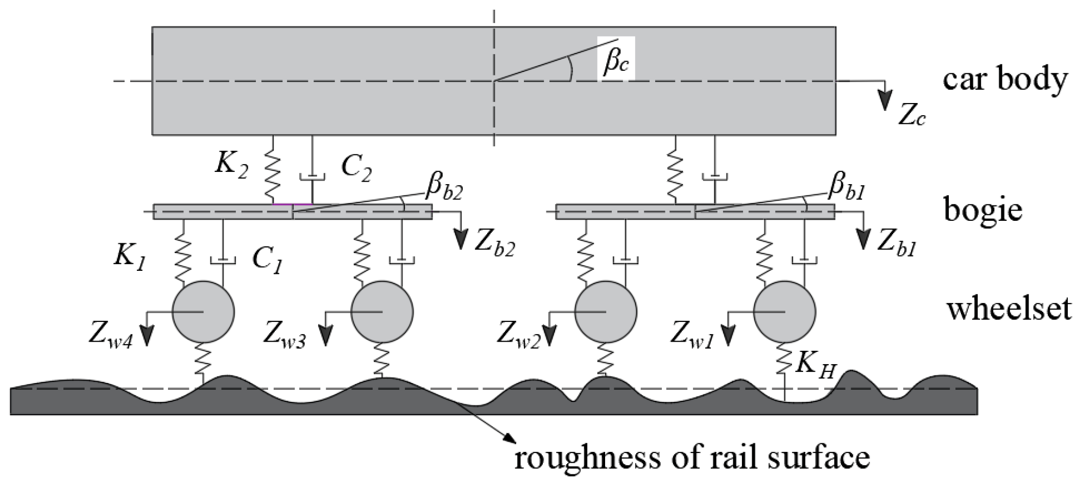
Figure 1. Simulation of the vehicle.
Applsci 09 04991 g001
Figure 2. Track irregularity (a) track irregularity with distance and (b) power spectrum density (PSD) with wavelength.
Applsci 09 04991 g002
Figure 3. The 3D coupled vehicle-track-soil model.
Applsci 09 04991 g003
Figure 4. Lab-test model and numerical model: (a) Lab-test model, (b) numerical model developed in LS-DYNA, and (c) cross section of the numerical model.
Applsci 09 04991 g004aApplsci 09 04991 g004b
Figure 5. Time history curves of pore water pressure: (a) pore-water-pressure measurement (PM)-1 and (b) PM-2.
Applsci 09 04991 g005
Figure 6. One-layered ground.
Applsci 09 04991 g006
Figure 7. Distribution of the pore water pressure.
Applsci 09 04991 g007
Figure 8. Time history curves of saturated ground: (a) Pore water pressure and (b) effective stress.
Applsci 09 04991 g008
Figure 9. Vibration responses with depth: (a) Pore water pressure, (b) effective stress, (c) total stress, and (d) displacement.
Applsci 09 04991 g009
Figure 10. Vibration responses with soil modulus: (a) Pore water pressure, (b) effective stress, (c) total stress, and (d) displacement.
Applsci 09 04991 g010
Figure 11. Multi-layered soils.
Applsci 09 04991 g011
Figure 12. Time history curves of vibration responses: (a) Pore water pressure at the surface of the first layer of ground, (b) pore water pressure at the surface of the second layer of ground, (c) total stress at the surface of the first layer of ground, and (d) total stress at the surface of the second layer of ground.
Applsci 09 04991 g012
Figure 13. Vibration responses: (a) Pore water pressure without piles, (b) pore water pressure with piles, (c) effective stress without piles, (d) effective stress without piles, (e) total stress without piles, (f) total stress with piles, (g) displacement without piles, and (h) displacement with piles.
Applsci 09 04991 g013aApplsci 09 04991 g013b
Figure 14. Time history curves of train-track interactions: (a) Wheel-rail contact force and (b) acceleration of car body.
Applsci 09 04991 g014
Table 1. Properties of the vehicle and slab track; CRH380 EMU = China Railway High-speed (CRH) 380 Electric Multiple Unit; CRTS = China Railway Track System; CA = cement asphalt.
PropertiesValues
CRH380 EMU Train [42]
Mass of the car body (kg)40,000
Mass of the bogie (kg)3200
Mass of the wheelset (kg)2400
Inertia of pitch motion of the car body(kg·m2)5.47 × 10⁵
Inertia of pitch motion of the bogie(kg·m2)6800
Primary suspension stiffness (N/m)1.04 × 106
Primary suspension damping (N·s/m)5 × 103
Secondary suspension stiffness (N/m)4 × 105
Secondary suspension damping (N·s/m)6 × 103
CRTS II slab track [19,37,38]
Mass density of the rail (kg/m3)7830
Modulus of elasticity of the rail (Pa)2.059 × 10¹¹
Poisson’s ratio of the rail 0.3
Stiffness of the rail pads (N/m)5.0 × 107 (dynamic stiffness)
Damping of the rail pads (N·s/m)7.5 × 104
Mass density of the concrete slab (kg/m3)2500
Modulus of elasticity of the concrete slab (Pa)3.6 × 10¹⁰ (reference static value, strain-rate dependent)
Poisson’s ratio of the concrete slab0.2
Mass density of the CA mortar (kg/m3)1900
Modulus of elasticity of the CA mortar (Pa)7 × 10⁹(reference static value, strain-rate dependent)
Poisson’s ratio of the CA mortar0.2
Mass density of the concrete base (kg/m3)2400
Modulus of elasticity of the concrete base (Pa)2.55 × 10¹⁰(reference static value, strain-rate dependent)
Poisson’s ratio of the concrete base0.2
Table 2. Properties of the water.
Density (kg/m3)Gravitational Acceleration (m/s2)Bulk Modulus (GPa)
10009.82.2
Table 3. Properties of multi-layered soils and piles.
ComponentsDepth (m)Density (kg/m3)Elastic Modulus (MPa)Poisson’s Ratio
SubgradeSurface layer0.423002000.25
Bottom layer2.319501500.35
Subgrade body221001100.3
GroundFirst layer2.41900420.3
Second layer13.12010830.36
Piles15.5220070000.2
Table 4. Maximum and minimum pore water pressures from experimental and numerical results.
PM-1PM-2
Experimental Value (kPa)Numerical Value (kPa)Difference (%)Experimental Value (kPa)Numerical Value (kPa)Difference (%)
Maximum18.8417.357.9117.4016.942.64
Minimum6.005.646.005.965.724.03
Table 5. Cases of multi-layered soils.
Subgrade (Three Layers)Ground (Two Layers)
Case 1--Saturated
Case 2DrySaturated
Case 3SaturatedSaturated
Case 4DryDry