Abstract
It is ascertained that the current communication systems will not be able to support the future network demands due to the increasing traffic, limitation of frequency resources, and high level of interference. Recently, beamforming techniques have been introduced to reduce the interference by redirecting the transmission towards the desired users only. While such beamforming enables better interference mitigation and improved network performance, the concerns on its effectiveness in dense deployment environments are arising. In this paper, the prospect of interference avoidance in location aware small cell environments using time division multiple access (TDMA) and beamforming is studied. The interference is reduced by identifying the aggressor small cell and transmit the beams towards the desired users at different times. Simulation results show that the proposed scheme is able to enhance the signal to interference plus noise ratio (SINR) by approximately 18 dB, enhance the user throughput by about 10 Mbps in comparison to small cell on/off control scheme with a discovery signal (SCon/off-DS), and improve the fairness index to about 95% in comparison to the baseline scheme. It is believed that the presented results promote the proposed scheme as an efficient interference management paradigm for the fifth generation (5G) communication systems.
1. Introduction
The future communication systems that operate in higher frequency bands promise to exploit wider bandwidths to cater higher data rates for the end users [1]. For instance, the highest bandwidth range that is obtainable in millimetre wave (mmWave) systems is approximately 10 Gigahertz (GHz) over a frequency range of 30–300 GHz which achieves about 100 bits/sec/Hz spectral efficiency, and obtains terabyte data rate at the physical layer [2,3]. This is triggered by the limitation of the current wireless communication systems in terms of spectrum limitation as well as fairness issues. In wireless systems, different channel conditions and/or improper resource allocation and scheduling are experienced by signals. Therefore, fairness is one of the issues worth to look at in such systems. In [4], the downlink throughput of OFDMA small cells is maximised subject to short-term and long-term fairness indices. This is achieved using a fixed transmission power. The proposed scheme utilises cumulative fairness constraint to replace the long-term fairness and further improve the system’s fairness. Similarly, the authors of [5] used non-orthogonal multiple access (NOMA) to maximise the fairness of drone small cells. More works on fairness can be found in [6,7,8].
Similarly, extensive researches focused on investigating bandwidths of up to 10 Terahertz (THz) because it offers extremely broader spectrum leading to huge capacity enhancements. Nevertheless, THz signals are very fragile in longer distances due to the high frequency. In other words, THz communication performs best in indoor capacities due to the proximity between transmitters and receivers [9,10]. On the other hand, multiple input multiple output (MIMO) technique is exploited to achieve enhanced beamsteering gains in which multiple antennas are tightly bundled together over a small spatial area. Subsequently, the technical and hardware complexities are few of many constraints that researchers had to realise in approaching the technique. The authors of [11] investigated the performance and the complications of signals phase-uncertainty when deploying low-complexity indoor wireless units that utilise hybrid beamforming techniques. The study concluded that the number and the size of antennas are proportional to the performance degradation.
The authors of [12] proposed a hybrid beamforming that is able to map a beamsteering codebook based on the channel state information (CSI). It consists of a digital beamformer that eliminates interference by dealing with regulated channel inversion (RCI) to reduce the overall complexity. It is meaningful to mention that the proposed algorithm is designed to eliminate inter-band-interference that is caused by orthogonal frequency division multiplexing (OFDM) carrier offsets (CFO) in [13].
The authors of [14] presented an experimental analysis of the in-band full-duplex communication (IBFD) end-fire arrangement array transceiver and then developed a MIMO testbed that communicates at 12.9 GHz carrier frequency. However, the scheme suppressed the self generated interference by using the OFDM techniques and did not show evaluations in terms of data rates and bit error rates. In view of that, the consideration of transmission and reception, proper channel modelling, and multipath and fading effects lead to the smart antennas techniques. In [15], smart antennas were categorised into adaptive arrays and switched beam antennas. While the latter describes the antennas that have multiple beams and able to switch to any beam at any given time, the former estimates the arrival direction and in-lines the beams with that direction, thereby resulting less interference.
Subsequently, the switched beam antennas do design the multi-user constellation depending on how interference is perceived. Interference is mostly eliminated or suppressed through minimum mean square error (MMSE) [16], zero-forcing (ZF) [17,18], or time division multiple access (TDMA) techniques [19]. TDMA techniques usually utilise time division multiplexing (TDM) training sequences to assist at the demodulating terminal. In that regard, the authors of [20] focused on achieving better synchronisation to realise the adaptive beamforming algorithms in real time co-channel communication systems.
The small cell technology on the other hand have expanded the capacity of the current communication systems by allowing more users to utilise more network resources with enhanced signals quality. Given the fact that most of future data exchange will originate from indoor environments along with the fragility of higher frequency signals; small cells are the most attractive solution that will solve for all the highlighted issues. With regards to that, service areas are often divided into equal set of squares whereby each square is served by single small cell to suppress interference power [21]. This is achieved by forcing other small cells within the service area to switch off to save power. However, interference caused by edge users transmitting with the maximum power may lead to grave performance deterioration. In [22] adaptive power control mechanism was proposed to reduce the interference by adaptively adjusting the transmission power to enhance the signal to interference plus noise ratio (SINR) and minimise the outage probability. The adaptation was done by either increasing or reducing the transmission power by a certain value and concurrently measure the SINR to achieve an optimal value. Additional works on interference management using power suppression techniques can be found in [23,24,25].
The authors of [26] presented a smart virtual antenna array that is deployable in 5G-IOT systems to avoid the interference by precisely directing the beams towards specific users. While transmitter signals are assumed to be in the form of generalised frequency division multiplexing (GFDM), the user signals are assumed to be OFDM signals. However, the authors of this paper understand that current wireless systems should be investigated extensively especially in views of small cells, beamforming, and TDMA technologies due to the existence of limited realistic channel models for future 5G communication systems and applications.
To the best of the authors knowledge, all works on beamforming techniques in long term evolutions (LTE) communication systems utilise location aware principles in approaching the objectives of the work. Without loss of generality, the authors have found no works that consider exploiting beamforming and TDMA techniques together to suppress the interference in dense small cell systems. Therefore, this paper proposes an interference avoidance algorithm that exploits beamforming and TDMA techniques in location aware small cell communication systems. This is achieved by redirecting the beams towards the users at different times in which the locations of the users are assumed to be known. The main contributions of this paper are summarised below:
- Realistic interference estimation and avoidance based on line-of-sight conditions. Therefore, favourable settings for propagation conditions are noted.
- Effective beamforming and TDMA algorithm for interference avoidance in dense indoor environments.
- The proposed scheme improves the network data rate in broader bandwidth transmissions.
- Realistic network model that is suitable for future communication systems.
- Motivation for further research directions, such as: interference avoidance in ultra-high frequencies and beamsteering techniques.
2. System Modelling and Problem Formulation
Crucial challenges and limitations in terms of the practicality of any simulation-based wireless communication system, need to be addressed especially channel and network representations. Here, the realisation of the channel and the annotations used in this simulation are introduced. As highlighted earlier, indoor facilities are expected to embrace the greatest portion of data exchange since higher frequencies are assumed to be effective within indoor capacities. Therefore, all simulation parameters including channel modelling parameters are tailored with respect to line-of-sight indoor environments.
In this paper, the set of small cells is denoted by whereby each small cell is assigned subchannels. The set of users associated to each small cell is denoted by . Moreover, and describe the maximum transmission power and the received power of each small cell, respectively. Without loss of generality, the necessary assumptions used in this paper are described below:
- Small scale fading (Rayleigh fading) is represented by the instantaneous received signal strength, which varies frequently in response to the separation between the transmitter and receiver. This is theoretically modelled using zeros-mean exponential distribution with unity deviation. However, for more practical analysis, Jake’s model [27] can be taken into account because it considers multipath, subchannel frequency, and the user speed.
- The service area (single indoor facility) is virtually controlled by small cell management system (ScMS) that is later connected to the LTE core network through the packets gateway (P-GW) [28].
- The network bandwidth = 20 MHz.
- The locations of small cells and users are entirely random (random distribution) in the simulation. However, once the locations of the small cells are generated, they remain unchanged until the iteration cycle completes. It later changes when the number of users is changed. Moreover, all locations and angles are assumed to be known to the ScMS.
Other simulation parameters are described in Table 1.

Table 1.
Simulation settings.
Signal propagation in the given scenario is dominated by line-of-sight path whereby any other reflected, scattered, or refracted signals are entirely neglected. Therefore, the channel gain between small cell and a user that are separated by a distance is obtained by the following [31]:
whereby is the pathloss that is calculated by [31], is the shadowing loss, and is the fading loss. It is also important to state that noise is Gaussian [31] whereby it equals to:
is the noise factor ≈2.5, is the noise spectral density ≈−174 dBm/Hz, and is the subchannel bandwidth ≈180 kHz.
Additionally, the simulation of the array antenna with respect to the parameters of Table 1 gives a beamwidth of 40° in which the main lobe is directed towards the desired user at a specific angle. The antenna polar beam pattern is presented in Figure 1.
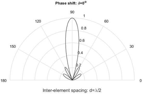
Figure 1.
Polar beam pattern of an array antenna that has 6 elements, inter-element spacing = , and .
2.1. Problem Formulation
Channel and interference in dense environments are unpredictable especially in random deployment scenarios where cells are distributed uniformly, which increases the complexity of channel estimation and interference cancellation processes. Omni-directional antennas (wider beamwidths) in conventional wireless communication systems have higher interference levels due to the reception from multiple angles. However, antennas in beamforming environments have narrow beamwidths and reception is limited to specific angles from the user point of view. Therefore, if the user has certain knowledge of the arrival angles of transmitted signals, it would curb down huge levels of interference. Nevertheless, it increases the complexity of the system and addresses more challenges such as the synchronisation issue.
The ratio of the desired signals in comparison to other channel factors is familiarly described by the SINR metric that is obtained by the following [31]:
whereby is the user association matrix of and that if the user u is associated to the small cell s, otherwise .
Looking at Equation (3), it can be concluded that if the interference power (denominator) is reduced, SINR is enhanced. Therefore, the problem is formulated as follows:
2.2. Evaluation Metrics
In this section, the parameters used to assess the performance of the proposed algorithm are introduced.
- Throughput [31]: this describes the competence of the network to deliver data. It also describes the effects of interference on the signals quality. Higher throughput means less interference, high SINR, and efficient resource allocation scheme. Throughput is obtained by the following:It is noteworthy to mention that Equation (5) is valid for the maximum obtainable throughput. However, the amount of successful packets delivery in real-time scenarios represents the network throughput.
- Jain’s Fairness model [32]: described by Equation (6); it is used to analyse how fairly the users can access the required throughput. Fairness index varies between 0 and 1 whereby the higher the index, the fairer the system.
- SINR: this compares the ratio of the received signal to interference plus noise.
3. Proposed Algorithm
As highlighted in Section 2, the synchronisation of both users and base stations increases the complexity of the beamforming system. To avoid this, we introduce the parameter at the ScMS, which is a matrix of that describes which user is receiving from which base station, is described below:
whereby is the beamwidth, and is the angle at which the user is located. Algorithm 1 describes how and are derived from . When user u is associated to small cell s, is said to equal 1. Subsequently, if the angle of user u is located within angles of the beam of small cell s, is set to 1. Similarly, is set to 1 if user u is located within angles of the beam of small cell i,
| Algorithm 1 Initialise |
|
Additionally, we introduce the parameter , which is also a matrix of . It describes the transmission time slot for user u, and obtained by the following:
whereby is the transmission time interval for a user in LTE.
In view of that, the ScMS forces s to transmit at the angle where the user is located. The maximum signal response will result at if , which is used in obtaining the summation of all antenna elements radiations i.e., array factor [33] as given by Equation (9).
whereby is the complex weight of the cth antenna element, is the wavelength, l is the inter-element spacing, and is the phase lead of the cth element.
At the ScMS, the base station transmission can now be described in terms of time and angle whereby the transmission of small cell s is set with respect to Table 2. Note that in Table 2 subchannels are considered in the transmission whereby the transmission is said to be in the downlink only i.e., only the small cells are instructed to adjust the transmission. For two interfering small cells s and i, and after is set according to Equation (8), is updated if user u is not receiving small cell s i.e., no interference. This is shown in Algorithm 2.
Table 2.
ScMS transmission codebook for cell s.
| Algorithm 2 Update |
|
It can now be claimed that the maximum is obtained if = 0. However, enhancements can be obtained if is minimised. Therefore, the in Equation (3) can now be obtained by the following:
Obtaining the correct angles where the users are located makes it easier to redirect the beams towards the desired user. Therefore, the minimum is obtained by Algorithm 2.
4. Results and Discussion
Here, the simulation results are presented to evaluate the relevance of the findings. The results of the algorithm presented in Section 3 are compared with the small cell on/off control scheme with a discovery signal (SCon/off-DS), location-aware self-optimisation (LASO) in [29]. When a nearby user requests specific amount of data rate from the small cell, the macrocell can provide the required coverage and mobility. Therefore, the SCon/off-DS scheme achieves downlink interference avoidance, and mitigation at the macrocell and the small cells, respectively. The LASO scheme improves the throughput by adjusting the power offset in downlink transmission by effectively locating the users. The authors have categorised the coverage area into two categories, namely: the non-dominantly interfered region (NDIR), and the interfered region (IR). The users in the NDIR experience high SINR, whereby the users in the IR experience low SINR. Additionally, beamforming scheme without TDMA technique is referred to as Pl-beamforming, the proposed algorithm is referred to as Sl-beamforming. Subsequently, the fairness of the beamforming schemes is later compared with baseline (BL) scheme in which interference is assumed to be zero i.e., the best performance, which is used to assess the feasibility and reliability of the proposed algorithm. Simulation results presented in this section are in-line with the assumptions of [10–100] users, 20 MHz bandwidth, kHz, service area , and 100 iterations.
The user throughput performance is illustrated in Figure 2a. Although the throughput achieved by the SCon/off-DS and the LASO in NDIR is relatively high when there are 10 users, the number quickly degrades as the number of users increase. However, both the Pl-beamforming and the Sl-beamforming schemes maintain a throughput level of approximately 16 Mbps and 18 Mbps, respectively. This is because the beams are effectively redirected towards the desired users only. Thus, reduces the interference to other users.

Figure 2.
Throughput and SINR comparison when increasing the number of users in the service area for all schemes.
This is evidenced by the SINR levels shown in Figure 2b whereby the superiority of the beamforming schemes is clear. This shows how significantly can the beamforming schemes reduce the interference in comparison to the other schemes. However, interference can still occur when the number of users increase due to the proximity of users.
Figure 3 shows the fairness level obtained by the Sl-beamforming. It is noteworthy to mention that the fairness results are compared to the BL scheme because the fairness was not evaluated in [29]. Nevertheless, the Sl-beamforming is able to perform better than the Pl-beamforming because narrower beamwidth and TDMA leads to less interference. Therefore, the Sl-beamforming is able to achieve about 95% fairness levels for 100 users. The overall performance of the Sl-beamforming promotes it as an efficient interference mitigation paradigm for future communication systems where the number of base stations is expected to increase.
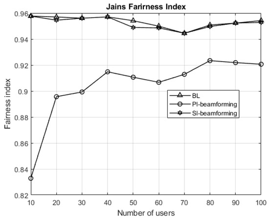
Figure 3.
Network fairness in comparison to the baseline scheme.
5. Conclusions
In this paper, the applicability of TDMA beamforming for future communication systems is studied and assessed. The paper addressed the concerns of future wireless communication followed by the features and the operations of beamforming. Subsequently, the Sl-beamforming is proposed for line-of-sight small cell systems in LTE architecture. The modelling of the network is tailored to give insights on the technical concerns and the achievements of the proposed scheme. Empirical simulations are demonstrated to enforce the applicability of the Sl-beamforming scheme whereby it is shown that the proposed scheme enhances the network SINR by about 18 dB, and user average throughput by about 10 Mbps in comparison to the NDIR schemes. It also increases the network fairness to approximately 95%. Future research directions will demonstrate the performance over non-line-of-sight scenarios, uplink communication, and ultra-dense environments. Resource scheduling algorithms should be added to the design, such as round robin and proportional fairness for more factual simulation. Furthermore, investigations over 5G communication channels and frequencies are recommended.
Author Contributions
Methodology, investigation, data curation, writing–original draft preparation, and writing–review and editing, K.S.M.; conceptualization, validation, formal analysis, supervision, and project administration, M.Y.A. and M.R.
Funding
This research received no external funding.
Conflicts of Interest
The authors declare no conflict of interest.
Abbreviations
The following abbreviations are used in this manuscript:
| 5G | Fifth Generation |
| BL | Base Line |
| CFO | Carrier Offsets |
| CSI | Channel State Information |
| GFDM | Generalised Frequency Division Multiplexing |
| GHz | Giga Hertz |
| IBFD | In-Band Full-Duplex |
| IoT | Internet of Things |
| IR | Interfered Region |
| LASO | Location Aware Self-Optimisation |
| LTE | Long Term Evolution |
| MIMO | Multiple Input Multiple Output |
| MMSE | Minimum Mean Square Error |
| mmWave | Millimetre Wave |
| NDIR | Non-Dominantly Interfered Region |
| OFDM | Orthogonal Frequency Division Multiplexing |
| P-GW | Packets Gateway |
| RCI | Regulated Channel Inversion |
| ScMs | Small cell Management System |
| SCon/off-DS | Small Cell on/off control scheme with Discovery Signal |
| SINR | Signal to Interference plus Noise Ratio |
| TDM | Tim Division Duplexing |
| TDMA | Time Division Multiple Access |
| THz | Tera Hertz |
| ZF | Zero Forcing |
References
- Akyildiz, I.F.; Jornet, J.M.; Han, C. TeraNets: Ultra-broadband communication networks in the terahertz band. IEEE Wirel. Commun. 2014, 21, 130–135. [Google Scholar] [CrossRef]
- Faisal, A.; Sarieddeen, H.; Dahrouj, H.; Al-Naffouri, T.Y.; Alouini, M.S. Ultra-massive MIMO systems at terahertz bands: Prospects and challenges. arXiv 2019, arXiv:1902.11090. [Google Scholar]
- Rangan, S.; Rappaport, T.S.; Erkip, E. Millimeter wave cellular wireless networks: Potentials and challenges. arXiv 2014, arXiv:1401.2560. [Google Scholar] [CrossRef]
- Guo, C.; Sheng, M.; Wang, X.; Zhang, Y. Throughput maximization with short-term and long-term Jain’s index constraints in downlink OFDMA systems. IEEE Trans. Commun. 2014, 62, 1503–1517. [Google Scholar] [CrossRef]
- Sohail, M.F.; Leow, C.Y. Maximized fairness for NOMA based drone communication system. In Proceedings of the 2017 IEEE 13th Malaysia International Conference on Communications (MICC), Johor Bahru, Malaysia, 28–30 November 2017; pp. 119–123. [Google Scholar] [CrossRef]
- Lee, Y.L.; Loo, J.; Chuah, T.C.; El-Saleh, A.A. Fair resource allocation with interference mitigation and resource reuse for LTE/LTE-A femtocell networks. IEEE Trans. Veh. Technol. 2016, 65, 8203–8217. [Google Scholar] [CrossRef]
- Ertürk, M.C.; Güvenç, I.; Mukherjee, S.; Arslan, H. Fair and QoS-oriented resource management in heterogeneous networks. EURASIP J. Wirel. Commun. Netw. 2013, 2013, 121. [Google Scholar] [CrossRef][Green Version]
- Lu, Z.; Bansal, T.; Sinha, P. Achieving user-level fairness in open-access femtocell-based architecture. IEEE Trans. Mob. Comput. 2012, 12, 1943–1954. [Google Scholar] [CrossRef]
- Lin, C.; Li, G.Y.L. Terahertz communications: An array-of-subarrays solution. IEEE Commun. Mag. 2016, 54, 124–131. [Google Scholar] [CrossRef]
- Federici, J.; Moeller, L. Review of terahertz and subterahertz wireless communications. J. Appl. Phys. 2010, 107, 6. [Google Scholar] [CrossRef]
- Lin, C.; Li, G.Y. Indoor terahertz communications: How many antenna arrays are needed? IEEE Trans. Wirel. Commun. 2015, 14, 3097–3107. [Google Scholar] [CrossRef]
- Yuan, H.; Yang, N.; Yang, K.; Han, C.; An, J. Hybrid Beamforming for MIMO-OFDM Terahertz Wireless Systems over Frequency Selective Channels. In Proceedings of the 2018 IEEE Global Communications Conference (GLOBECOM), Abu Dhabi, UAE, 9–13 December 2018; pp. 1–6. [Google Scholar] [CrossRef]
- Sathananthan, K.; Tellambura, C. Probability of error calculation of OFDM systems with frequency offset. IEEE Trans. Commun. 2001, 49, 1884–1888. [Google Scholar] [CrossRef]
- Honma, N.; Heianna, S.; Kawagoe, A.; Tada, S.; Yamamoto, Y.; Yuan, Q.; Chen, Q. Enabling Full-Duplex MIMO Communication Exploiting Array Antenna Arrangement. In Proceedings of the 2018 International Symposium on Antennas and Propagation (ISAP), Busan, Korea, 23–26 October 2018; pp. 1–2. [Google Scholar]
- Misra, G.; Agarwal, K.; Agarwal, A.; Ghosh, K.; Agarwal, S. Smart Antenna for Wireless Cellular Communication-A Technological Analysis on Architecture, Working Mechanism, Drawbacks and Future Scope. In Proceedings of the 2018 2nd International Conference on (I-SMAC), Palladam, India, 30–31 August 2018; pp. 37–41. [Google Scholar] [CrossRef]
- Patcharamaneepakorn, P.; Armour, S.; Doufexi, A. On the equivalence between SLNR and MMSE precoding schemes with single-antenna receivers. IEEE Commun. Lett. 2012, 16, 1034–1037. [Google Scholar] [CrossRef]
- Peel, C.B.; Hochwald, B.M.; Swindlehurst, A.L. A vector-perturbation technique for near-capacity multiantenna multiuser communication-part I: Channel inversion and regularization. IEEE Trans. Commun. 2005, 53, 195–202. [Google Scholar] [CrossRef]
- Wiesel, A.; Eldar, Y.C.; Shamai, S. Zero-Forcing Precoding and Generalized Inverses. IEEE Trans. Signal Process. 2008, 56, 4409–4418. [Google Scholar] [CrossRef]
- Khang, Y.Y.; Zhangt, J.K.; Yu, H.Y. Finite-alphabet beamformed NOMA for multiuser MISO broadcast visible light communications. In Proceedings of the 2018 IEEE 10th Sensor Array and Multichannel Signal Processing Workshop (SAM), Sheffield, UK, 8–11 July 2018; pp. 563–567. [Google Scholar] [CrossRef]
- Leary, J.; Gooch, R. Adaptive beamforming for TDMA signals. In Proceedings of the Twenty-Ninth Asilomar Conference on Signals, Systems and Computers, Pacific Grove, CA, USA, 30 October–1 November 1995; Volume 2, pp. 1378–1382. [Google Scholar] [CrossRef]
- Busson, A.; Zitoune, L.; Vèque, V.; Jabbari, B. Outage analysis of integrated mesh LTE femtocell networks. In Proceedings of the IEEE Global Communications Conference (GLOBECOM), Austin, TX, USA, 8–12 December 2014; pp. 187–192. [Google Scholar] [CrossRef]
- Saad, S.A.; Ismail, M.; Nordin, R.; Ahmed, A.U. A fractional path-loss compensation based power control technique for interference mitigation in LTE-A femtocell networks. Phys. Commun. 2016, 21, 1–9. [Google Scholar] [CrossRef]
- Lin, S.; Ni, W.; Tian, H.; Liu, R.P. An evolutionary game theoretic framework for femtocell radio resource management. IEEE Trans. Wirel. Commun. 2015, 14, 6365–6376. [Google Scholar] [CrossRef]
- Nam, C.; Joo, C.; Bahk, S. Joint subcarrier assignment and power allocation in full-duplex OFDMA networks. IEEE Trans. Wirel. Commun. 2015, 14, 3108–3119. [Google Scholar] [CrossRef]
- LeAnh, T.; Tran, N.H.; Saad, W.; Le, L.B.; Niyato, D.; Ho, T.M.; Hong, C.S. Matching theory for distributed user association and resource allocation in cognitive femtocell networks. IEEE Trans. Veh. Technol. 2017, 66, 8413–8428. [Google Scholar] [CrossRef]
- Datta, J.; Lin, H.P. Interference Avoidance using Spatial Modulation based Location Aware Beamforming in Cognitive Radio IOT Systems. Adv. Sci. Technol. Eng. Syst. J. 2018, 3, 49–57. [Google Scholar] [CrossRef]
- Jakes, W. Microwave Mobile Communications; IEEE and John Wiley & Sons: Hoboken, NJ, USA, 1974. [Google Scholar]
- Lee, Y.L.; Loo, J.; Chuah, T.C. Dynamic resource management for lte-based hybrid access femtocell systems. IEEE Syst. J. 2016, 12, 959–970. [Google Scholar] [CrossRef]
- Choi, J.H.; Shin, D.J. Location-Aware Self-Optimization for Interference Management in Ultra-Dense Small Cell Networks. IEEE Commun. Lett. 2018, 22, 2555–2558. [Google Scholar] [CrossRef]
- Ibrahim, L.F.; Salman, H.A.; Sery, S.Y.; Taha, Z. Using clustering techniques to plan indoor Femtocell base stations layout in multi-floors. Comput. J. 2019, 62, 919–930. [Google Scholar] [CrossRef]
- Loong, L.Y. Radio Resource Management for Long-term Evolution Based Heterogeneous Cellular Networks. Ph.D. Thesis, Multimedia University, Cyberjaya, Malaysia, 2016. [Google Scholar]
- Jain, R.; Durresi, A.; Babic, G. Throughput Fairness Index: An Explanation; ATM Forum Contribution 99. , 1999. Available online: https://www.cse.wustl.edu/~jain/atmf/ftp/af_fair.pdf (accessed on 1 October 2019).
- Litva, J.; Lo, T.K. Digital Beamforming in Wireless Communications; Artech House, Inc.: Norwood, MA, USA, 1996. [Google Scholar]
© 2019 by the authors. Licensee MDPI, Basel, Switzerland. This article is an open access article distributed under the terms and conditions of the Creative Commons Attribution (CC BY) license (http://creativecommons.org/licenses/by/4.0/).