Effect of Boron and Oxygen on the Structure and Properties of Protective Decorative Cr–Al–Ti–N Coatings Deposited by Closed Field Unbalanced Magnetron Sputtering (CFUBMS)

 ,
, 

Abstract
:1. Introduction
2. Materials and Methods
3. Results
4. Discussion
5. Conclusions
Author Contributions
Funding
Conflicts of Interest
References
- Holubář, P.; Jílek, M.; Šíma, M. Nanocomposite nc-TiAlSiN and nc-TiN–BN coatings: Their applications on substrates made of cemented carbide and results of cutting tests. Surf. Coat. Technol. 1999, 120–121, 184–188. [Google Scholar] [CrossRef]
- Holzschuh, H. Deposition of Ti–B–N (single and multilayer) and Zr–B–N coatings by chemical vapor deposition techniques on cutting tools. Thin Solid Films 2004, 469, 92–98. [Google Scholar] [CrossRef]
- Kiryukhantsev-Korneev, F.V.; Shirmanov, N.A.; Sheveiko, A.N.; Levashov, E.A.; Petrzhik, M.I.; Shtanskii, D.V. Nanostructural wear-resistant coatings produced on metal-cutting tools by electric-arc evaporation and magnetronic sputtering. Russ. Eng. Res. 2010, 30, 910–920. [Google Scholar] [CrossRef]
- Mitterer, C.; Holler, F.; Üstel, F.; Heim, D. Application of hard coatings in aluminium die casting—Soldering, erosion and thermal fatigue behaviour. Surf. Coat. Technol. 2000, 125, 233–239. [Google Scholar] [CrossRef]
- Stoiber, M.; Badisch, E.; Lugmair, C.; Mitterer, C. Low-friction TiN coatings deposited by PACVD. Surf. Coat. Technol. 2003, 163, 451–456. [Google Scholar] [CrossRef]
- He, J.; Miyake, S.; Setsuhara, Y.; Shimizu, I.; Suzuki, M.; Numata, K.; Saito, H. Improved anti-wear performance of nanostructured titanium boron nitride coatings. Wear 2001, 249, 498–502. [Google Scholar] [CrossRef]
- Berger, M.; Hogmark, S. Tribological properties of selected PVD coatings when slid against ductile materials. Wear 2002, 252, 557–565. [Google Scholar] [CrossRef]
- Pierson, J.-F.; Chapusot, V.; Billard, A.; Alnot, M.; Bauer, P. Characterisation of reactively sputtered Ti–B–N and Ti–B–O coatings. Surf. Coat. Technol. 2002, 151, 526–530. [Google Scholar] [CrossRef]
- Lin, S.T.; Lee, C. Characteristics of sputtered Ta–B–N thin films as diffusion barriers between copper and silicon. Appl. Surf. Sci. 2006, 253, 1215–1221. [Google Scholar] [CrossRef]
- Vlček, J.; Steidl, P.; Kohout, J.; Čerstvý, R.; Zeman, P.; Prokšová, Š.; Perina, V. Hard nanocrystalline Zr–B–C–N films with high electrical conductivity prepared by pulsed magnetron sputtering. Surf. Coat. Technol. 2013, 215, 186–191. [Google Scholar] [CrossRef]
- Aouadi, S.; Debessai, M.; Namavar, F.; Wong, K.; Mitchell, K. Titanium boron nitride films grown by ion beam assisted deposition: Chemical and optical characterization. Surf. Coat. Technol. 2004, 183, 369–377. [Google Scholar] [CrossRef]
- Anjum, F.; Fryauf, D.M.; Gold, J.; Ahmad, R.; Cormia, R.D.; Kobayashi, N.P. Study of optical and structural properties of sputtered aluminum nitride films with controlled oxygen content to fabricate Distributed Bragg Reflectors for ultraviolet A. Opt. Mater. 2019, 98, 109405. [Google Scholar] [CrossRef]
- Shtansky, D.V.; Petrzhik, M.I.; Bashkova, I.A.; Kiryukhantsev-Korneev, F.V.; Sheveĭko, A.N.; Levashov, E.A. Adhesion, friction, and deformation characteristics of Ti-(Ca,Zr)-(C,N,O,P) coatings for orthopedic and dental implants. Phys. Solid State 2006, 48, 1301–1308. [Google Scholar] [CrossRef]
- Sheftel, E.N.; Harin, E.V.; Tedzhetov, V.A.; Kiryukhantsev-Korneev, P.V.; Levashov, E.A.; Perov, N.S.; Titova, A.O. Magnetic structure and magnetic properties of nanocrystalline and amorphous Fe–Zr–N films. Phys. B Condens. Matter 2016, 494, 13–19. [Google Scholar] [CrossRef]
- Choy, K. Chemical vapour deposition of coatings. Prog. Mater. Sci. 2003, 48, 57–170. [Google Scholar] [CrossRef]
- Weber, M.; Iatsunskyi, I.; Coy, E.; Miele, P.; Cornu, D.; Bechelany, M. Novel and Facile Route for the Synthesis of Tunable Boron Nitride Nanotubes Combining Atomic Layer Deposition and Annealing Processes for Water Purification. Adv. Mater. Interfaces 2018, 5, 1800056. [Google Scholar] [CrossRef]
- Snure, M.; Paduano, Q.; Hamilton, M.; Shoaf, J.; Mann, J.M. Optical characterization of nanocrystalline boron nitride thin films grown by atomic layer deposition. Thin Solid Films 2014, 571, 51–55. [Google Scholar] [CrossRef]
- Weber, M.; Coy, E.; Iatsunskyi, I.; Yate, L.; Miele, P.; Bechelany, M. Mechanical properties of boron nitride thin films prepared by atomic layer deposition. CrystEngComm 2017, 19, 6089–6094. [Google Scholar] [CrossRef]
- Teer, D. Magnetron Sputter Ion Plating. U.S. Patent No. 5556519A 17 September 1996. [Google Scholar]
- Teer, D. Technical note: A magnetron sputter ion-plating system. Surf. Coat. Technol. 1989, 39, 565–572. [Google Scholar] [CrossRef]
- Kelly, P.J.; Arnell, R.D. Magnetron sputtering: A review of recent developments and applications. Vacuum 2000, 56, 159–172. [Google Scholar] [CrossRef]
- Arslan, E.; Efeoglu, I. Effect of heat treatment on TiN films deposited by CFUBMS. Mater. Charact. 2004, 53, 29–34. [Google Scholar] [CrossRef]
- Yao, S.H.; Su, Y.L.; Kao, W.H. Effect of Ag/W addition on the Vwar performance of CrN coatings prepared by RF unbalanced magnetron sputtering. Mater. Sci. Eng. 2005, 25, 88–92. [Google Scholar] [CrossRef]
- Zhang, F.; Yan, S.; Yin, F.; He, J. Microstructures and mechanical properties of Ti–Cr–N/Al–Ti–Cr based coatings prepared by plasma nitriding 5083 Al alloys co-deposited with Ti–Cr films. Vacuum 2018, 157, 115–123. [Google Scholar] [CrossRef]
- Kabir, M.S.; Munroe, P.; Zhou, Z.; Xie, Z. Scratch adhesion and tribological behavior of graded Cr/CrN/CrTiN coatings synthesized by closed-field unbalanced magnetron sputtering. Wear 2017, 380–381, 163–175. [Google Scholar] [CrossRef]
- Xu, J.; Li, Z.; Xie, Z.H.; Munroe, P. Uniting superhardness and damage-tolerance in a nanosandwich-structured Ti–B–N coating. Scr. Mater. 2014, 74, 88–91. [Google Scholar] [CrossRef]
- Lu, Y.H.; Shen, Y.G.; Zhou, Z.F.; Li, K.Y. Effects of B content and wear parameters on dry sliding wear behaviors of nanocomposite Ti–B–N thin films. Wear 2007, 262, 1372–1379. [Google Scholar] [CrossRef]
- Ma, Q.; Zhou, F.; Gao, S.; Wu, Z.; Wang, Q.; Chen, K.; Zhou, Z.; Li, L.K. Lawrence Kwok-Yan Li. Influence of boron content on the microstructure and tribological properties of Cr-B-N coatings in water lubrication. Appl. Surf. Sci. 2016, 377, 394–405. [Google Scholar] [CrossRef]
- Kiryukhantsev-Korneev, F.V.; Petrzhik, M.I.; Sheveiko, A.N.; Levashov, E.A.; Shtanskii, D.V. Effect of Al, Si, and Cr on the thermal stability and high-temperature oxidation resistance of coatings based on titanium boronitride. Phys. Met. Metallogr. 2007, 104, 167–174. [Google Scholar] [CrossRef]
- Kiryukhantsev-Korneev, F.V.; Novikov, A.V.; Sagalova, T.B.; Petrzhik, M.I.; Levashov, E.A.; Shtansky, D.V. A comparative study of microstructure, oxidation resistance, mechanical, and tribological properties of coatings in Mo–B–(N), Cr–B–(N) and Ti–B–(N) systems. Phys. Met. Metallogr. 2017, 118, 1136–1146. [Google Scholar] [CrossRef]
- Karvankova, P.; Veprek-Heijman, M.G.J.; Azinovic, D.; Veprek, S. Properties of superhard nc-TiN/a-BN and nc-TiN/a-BN/a-TiB2 nanocomposite coatings prepared by plasma induced chemical vapor deposition. Surf. Coat. Technol. 2006, 200, 2978–2989. [Google Scholar] [CrossRef]
- Lee, J.W.; Chih-Hong, C.; Chen, H.W.; Ho, L.W.; Duh, J.G.; Chan, Y.C. The influence of boron contents on the microstructure and mechanical properties of Cr–B–N thin films. Vacuum 2013, 87, 191–194. [Google Scholar] [CrossRef]
- Kiryukhantsev-Korneev, P.V.; Pierson, J.F.; Bychkova, M.Y.; Manakova, O.S.; Levashov, E.A.; Shtansky, D.V. Comparative Study of Sliding, Scratching, and Impact-Loading Behavior of Hard CrB2 and Cr–B–N Films. Tribol. Lett. 2016, 63, 44. [Google Scholar] [CrossRef]
- Budna, K.P.; Mayrhofer, P.H.; Neidhardt, J.; Hegedũs, É.; Kovács, I.; Tóth, L.; Pécz, B.; Mitterer, C. Effect of nitrogen-incorporation on structure, properties and performance of magnetron sputtered CrB2. Surf. Coat. Technol. 2008, 202, 3088–3093. [Google Scholar] [CrossRef]
- Budna, K.; Neidhardt, J.; Mayrhofer, P.; Mitterer, C.; Mayrhofer, P. Synthesis–structure–property relations for Cr–B–N coatings sputter deposited reactively from a Cr–B target with 20at% B. Vacuum 2008, 82, 771–776. [Google Scholar] [CrossRef]
- Cheng, C.H.; Lee, J.W.; Ho, L.W.; Chen, H.W.; Chan, Y.C.; Duh, J.G. Microstructure and mechanical property evaluation of pulsed DC magnetron sputtered Cr–B and Cr–B–N films. Surf. Coat. Technol. 2011, 206, 1711–1719. [Google Scholar] [CrossRef]
- Sakamaoto, Y.; Nose, M.; Mae, T.; Honbo, E.; Zhou, M.; Nogi, K. Structure and properties of Cr–B, Cr–B–N and multilayer Cr–B/Cr–B–N thin films prepared by r.f.-sputtering. Surf. Coat. Technol. 2003, 174, 444–449. [Google Scholar] [CrossRef]
- Zhou, M.; Nose, M.; Nogi, K. Influence of nitrogen on the structure and mechanical properties of r.f.-sputtered Cr–B–N thin films. Surf. Coat. Technol. 2004, 183, 45–50. [Google Scholar] [CrossRef]
- Kiryukhantsev-Korneev, P.V.; Pierson, J.F.; Petrzhik, M.I.; Alnot, M.; Levashov, E.A.; Shtansky, D.V. Effect of nitrogen partial pressure on the structure, physical and mechanical properties of CrB2 and Cr–B–N films. Thin Solid Films 2009, 517, 2675–2680. [Google Scholar] [CrossRef]
- Jahodova, V.; Ding, X.Z.; Seng, D.H.; Gulbinski, W.; Louda, P. Mechanical, tribological and corrosion properties of CrBN films deposited by combined direct current and radio frequency magnetron sputtering. Thin Solid Films 2013, 544, 335–340. [Google Scholar] [CrossRef]
- Wang, Q.; Zhou, F.; Callisti, M.; Polcar, T.; Kong, J.; Yan, J. Study on the crack resistance of CrBN composite coatings via nano-indentation and scratch tests. Alloys Compd. 2017, 708, 1103–1109. [Google Scholar] [CrossRef]
- Lua, Y.H.; Zhou, Z.F.; Sit, P.; Shen, Y.G.; Li, K.Y.; Chen, H. X-Ray photoelectron spectroscopy characterization of reactively sputtered Ti–B–N thin films. Surf. Coat. Technol. 2004, 187, 98–105. [Google Scholar] [CrossRef]
- Lin, J.; Moore, J.; Moerbe, W.; Pinkas, M.; Mishra, B.; Doll, G.; Sproul, W. Structure and properties of selected (Cr–Al–N, TiC–C, Cr–B–N) nanostructured tribological coatings. Int. J. Refract. Met. Hard Mater. 2010, 28, 2–14. [Google Scholar] [CrossRef]
- Kiryukhantsev-Korneev, P.V.; Phiri, J.; Gladkov, V.I.; Ratnikov, S.N.; Yakovlev, M.G.; Levashov, E.A. Erosion and Abrasion Resistance, Mechanical Properties, and Structure of the TiN, Ti–Cr–Al–N and Cr–Al–Ti–N Coatings Deposited by CFUBMS. Prot. Met. Phys. Chem. Surf. 2019, 55, 913–923. [Google Scholar] [CrossRef]
- Wu, Z.T.; Qi, Z.B.; Zhang, D.F.; Wei, B.B.; Wang, Z.C. Evaluating the influence of adding Nb on microstructure, hardness and oxidation resistance of CrN coating. Surf. Coat. Technol. 2016, 289, 45–51. [Google Scholar] [CrossRef]
- Lin, J.; Mishra, B.; Moore, J.J.; Sproul, W.D. Microstructure, mechanical and tribological properties of Cr1−xAlxN films deposited by pulsed-closed field unbalanced magnetron sputtering (P-CFUBMS). Surf. Coat. Technol. 2006, 201, 4329–4334. [Google Scholar] [CrossRef]
- Leyland, A.; Matthews, A. On the significance of the H/E ratio in Vwar control: A nanocomposite coating approach to optimised tribological behaviour. Wear 2000, 246, 1–11. [Google Scholar] [CrossRef]
- Levashov, E.A.; Petrzhik, M.I.; Shtansky, D.V.; Kiryukhantsev-Korneev, P.V.; Sheveyko, A.N.; Valiev, R.Z.; Gunderov, D.V.; Prokoshkin, S.D.; Korotitskiy, A.V.; Smolin, A.Y. Nanostructured titanium alloys and multicomponent bioactive films: Mechanical behavior at indentation. Mater. Sci. Eng. 2013, 570, 51–62. [Google Scholar] [CrossRef]
- Kiryukhantsev-Korneev, P.V.; Iatsyuk, I.V.; Shvindina, N.V.; Levashov, E.A.; Shtansky, D.V. Comparative investigation of structure, mechanical properties, and oxidation resistance of Mo-Si-B and Mo-Al-Si-B coatings. Corros. Sci. 2017, 123, 319–327. [Google Scholar] [CrossRef]
- Kiryukhantsev-Korneev, F.V.; Lemesheva, M.V.; Shvyndina, N.V.; Levashov, E.A.; Potanin, A.Y. Structure, Mechanical Properties, and Oxidation Resistance of ZrB2, ZrSiB, and ZrSiB/SiBC Coatings. Prot. Met. Phys. Chem. Surf. 2018, 54, 1147–1156. [Google Scholar] [CrossRef]
- Kiryukhantsev-Korneev, P.V.; Pierson, J.F.; Kuptsov, K.A.; Shtansky, D.V. Hard Cr–Al–Si–B–(N) coatings deposited by reactive and non-reactive magnetron sputtering of CrAlSiB target. Appl. Surf. Sci. 2014, 314, 104–111. [Google Scholar] [CrossRef]
- Shtansky, D.V.; Kiryukhantsev-Korneev, P.V.; Sheveyko, A.N.; Kutyrev, A.E.; Levashov, E.A. Hard tribological Ti–Cr–B–N coatings with enhanced thermal stability, corrosion- and oxidation resistance. Surf. Coat. Technol. 2007, 202, 861–865. [Google Scholar] [CrossRef]
- Levashov, E.A.; Kosayanin, V.I.; Krukova, L.M.; Moore, J.J.; Olson, D.L. Structure and properties of Ti-C-B composite thin films produced by sputtering of composite TiC-TiB2 targets. Surf. Coat. Technol. 1997, 92, 34–41. [Google Scholar] [CrossRef]
- Shtansky, D.V.; Sheveyko, A.N.; Sorokin, D.I.; Lev, L.C.; Mavrin, B.N.; Kiryukhantsev-Korneev, P.V. Structure and properties of multi-component and multilayer TiCrBN/WSex coatings deposited by sputtering of TiCrB and WSe2 targets. Surf. Coat. Technol. 2008, 202, 5953–5961. [Google Scholar] [CrossRef]


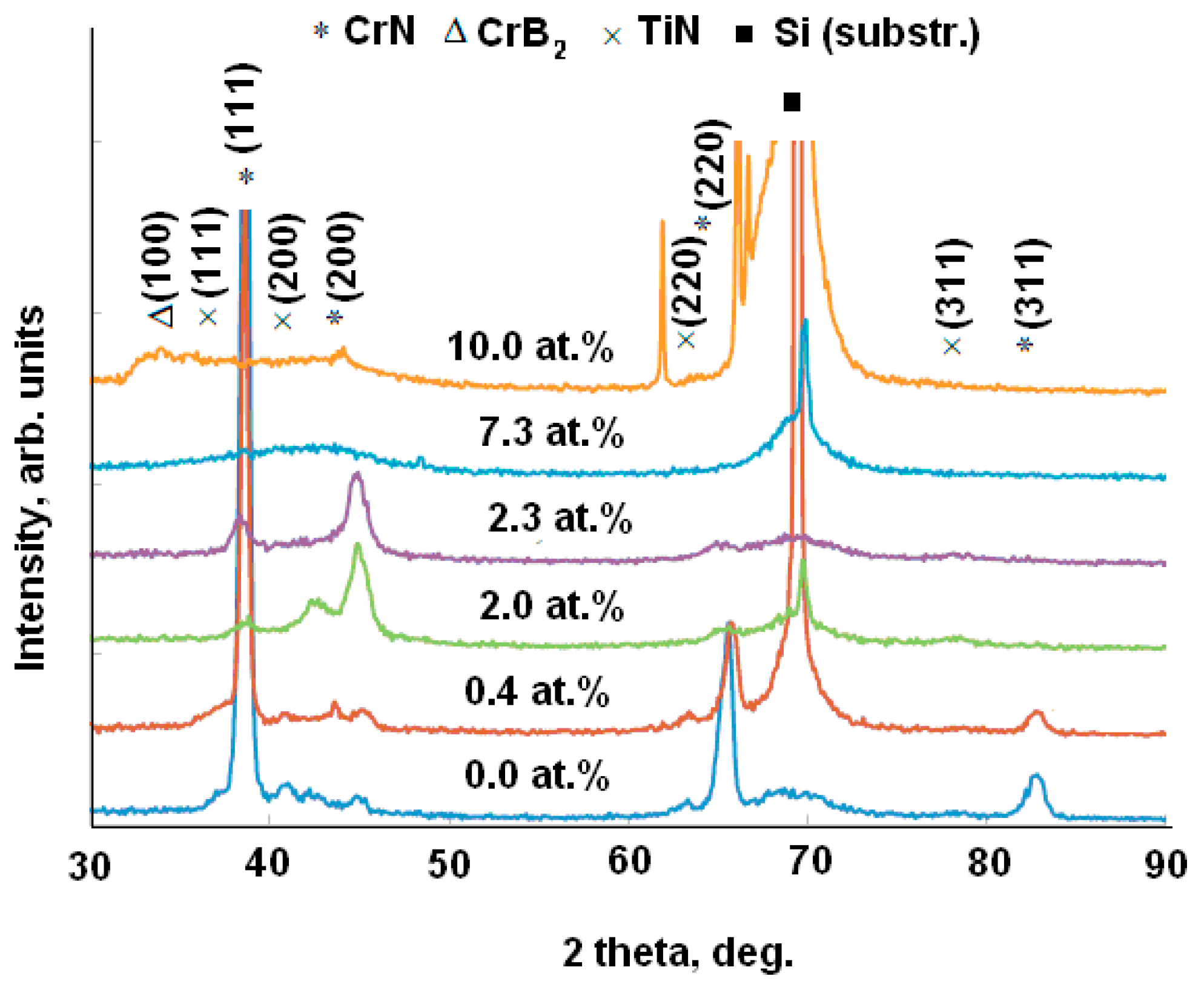
| Specimen | ITiB, A | Elemental Composition, at.% | Coating Thickness, μm | ||||||
|---|---|---|---|---|---|---|---|---|---|
| Cr | Al | Ti | B | N | O | C | |||
| P1 | 0 | 38.9 | 8.6 | 4.2 | 0 | 43.5 | 4.3 | 0.5 | 3.5 |
| P2 | 0.5 | 38.0 | 14.6 | 5.1 | 0.4 | 38.7 | 2.4 | 0.8 | 3.5 |
| P3 | 1 | 41.0 | 11.6 | 6.1 | 2.0 | 38.1 | 1.0 | 0.2 | 3.0 |
| P4 | 1.5 | 35.0 | 16.1 | 8.5 | 2.3 | 35.2 | 2.4 | 0.5 | 3.0 |
| P5 | 3 | 35.5 | 12.7 | 10.2 | 7.3 | 33.0 | 0.3 | 0.1 | 4.0 |
| P6 | 5 | 33.5 | 12.0 | 11.7 | 10.0 | 32.0 | 0.5 | 0.2 | 3.5 |
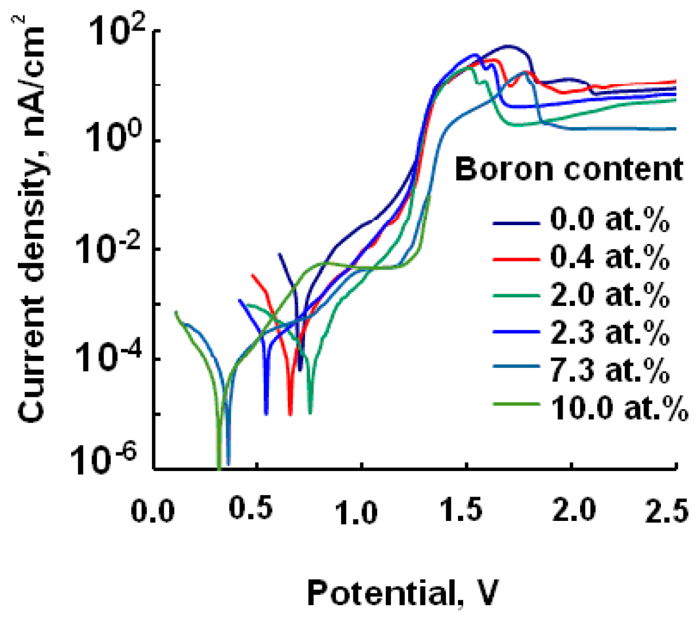
| Specimen | B, at.% | U, V | Corrosion Current, nA/cm2 |
|---|---|---|---|
| P1 | 0 | 0.808 | 140 |
| P2 | 0.4 | 0.725 | 22 |
| P3 | 2 | 0.660 | 18 |
| P4 | 2.3 | 0.650 | 27 |
| P5 | 7.3 | 0.330 | 36 |
| P6 | 10 | 0.310 | 39 |
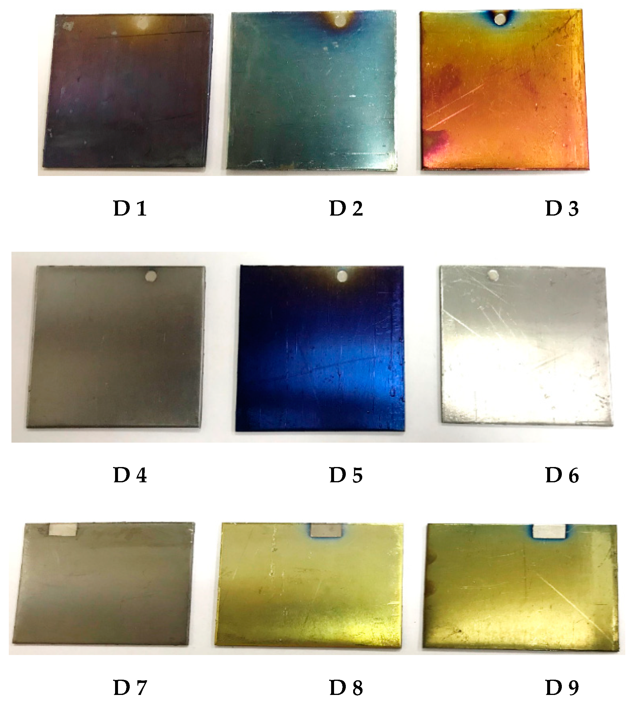
| Specimen | QAr/Qair, cm3/min | τ, min | Elemental Composition, at.% | Coating Thickness, μm | Coloration | ||||||
|---|---|---|---|---|---|---|---|---|---|---|---|
| Cr | Al | Ti | B | N | O | C | |||||
| D1 | 5/40 | 10 | 27.2 | 5.2 | 13.8 | 5.1 | 16.7 | 27.4 | 4.6 | 0.04 | Violet |
| D2 | 5/40 | 20 | 22.7 | 3.8 | 13.8 | 3.9 | 11.5 | 40.2 | 4.1 | 0.07 | Light-blue |
| D3 | 5/40 | 30 | 46.7 | 19.6 | 13.9 | 10.4 | 5.6 | 2.9 | 0.9 | 0.7 | Rose |
| D4 | 30/30 | 10 | 37.5 | 11.5 | 8.4 | 5.9 | 29.8 | 6.4 | 0.5 | 0.2 | Gray |
| D5 | 30/30 | 20 | 14.7 | 2.7 | 13.3 | 6.8 | 11.0 | 40.8 | 10.7 | 0.5 | Dark-blue |
| D6 | 30/30 | 30 | 33.4 | 11.4 | 11.3 | 8.5 | 30.4 | 4.1 | 0.9 | 0.6 | Gray |
| D7 | 15/30 | 10 | 37.9 | 10.8 | 8.4 | 5.7 | 29.3 | 7.2 | 0.7 | 0.4 | Gray |
| D8 | 15/30 | 20 | 40.0 | 11.2 | 9.0 | 6.2 | 28.2 | 4.9 | 0.5 | 0.5 | Yellow |
| D9 | 15/30 | 30 | 36.8 | 11.9 | 9.2 | 6.3 | 31.2 | 4.2 | 0.4 | 1.3 | Hazel |
© 2019 by the authors. Licensee MDPI, Basel, Switzerland. This article is an open access article distributed under the terms and conditions of the Creative Commons Attribution (CC BY) license (http://creativecommons.org/licenses/by/4.0/).
Share and Cite
Kiryukhantsev-Korneev, P.V.; Amankeldina, Z.S.; Sheveyko, A.N.; Vorotilo, S.; Levashov, E.A. Effect of Boron and Oxygen on the Structure and Properties of Protective Decorative Cr–Al–Ti–N Coatings Deposited by Closed Field Unbalanced Magnetron Sputtering (CFUBMS). Appl. Sci. 2019, 9, 4977. https://doi.org/10.3390/app9224977
Kiryukhantsev-Korneev PV, Amankeldina ZS, Sheveyko AN, Vorotilo S, Levashov EA. Effect of Boron and Oxygen on the Structure and Properties of Protective Decorative Cr–Al–Ti–N Coatings Deposited by Closed Field Unbalanced Magnetron Sputtering (CFUBMS). Applied Sciences. 2019; 9(22):4977. https://doi.org/10.3390/app9224977
Chicago/Turabian StyleKiryukhantsev-Korneev, Ph. V., Zh. S. Amankeldina, A. N. Sheveyko, S. Vorotilo, and E. A. Levashov. 2019. "Effect of Boron and Oxygen on the Structure and Properties of Protective Decorative Cr–Al–Ti–N Coatings Deposited by Closed Field Unbalanced Magnetron Sputtering (CFUBMS)" Applied Sciences 9, no. 22: 4977. https://doi.org/10.3390/app9224977
APA StyleKiryukhantsev-Korneev, P. V., Amankeldina, Z. S., Sheveyko, A. N., Vorotilo, S., & Levashov, E. A. (2019). Effect of Boron and Oxygen on the Structure and Properties of Protective Decorative Cr–Al–Ti–N Coatings Deposited by Closed Field Unbalanced Magnetron Sputtering (CFUBMS). Applied Sciences, 9(22), 4977. https://doi.org/10.3390/app9224977