Review

Time Shared Optical Network (TSON): A Programmable Network Edge Solution for Multi-Access Support

High Performance Networks Group, Smart Internet Lab, School of Computer Science, Electrical and Electronic Engineering, and Engineering Maths, Merchant Venturers Building, University of Bristol, Woodland Road, Bristol BS8 1UB, UK
*
Author to whom correspondence should be addressed.
Appl. Sci. 2019, 9(22), 4786; https://doi.org/10.3390/app9224786
Submission received: 30 September 2019 / Revised: 31 October 2019 / Accepted: 4 November 2019 / Published: 8 November 2019
(This article belongs to the Special Issue Optical Network Evolution Towards 5G)

Abstract

:
The time shared optical network (TSON) has been proposed as a dynamic optical transport network solution to provide high bandwidth and low latency connectivity in support of 5G technology and beyond. This work reviews the TSON evolution stages developed in the framework of the U.K. national project Towards Ultimate Convergence of All Networks (TOUCAN). The details of the TSON architecture and its various development phases are discussed, and the performance of its latest implementation is evaluated through relevant demonstration activities across the Smart Internet Lab’s 5G (5GUK) test network.

1. Introduction

Towards Ultimate Convergence of All Networks (TOUCAN) [1] is a University of Bristol-led research project funded by the U.K. Engineering and Physical Sciences Research Council (EPSRC). The TOUCAN aims to achieve ultimate network convergence, enabled by a new technology agnostic architecture targeting a wide range of applications and end users. The architecture will facilitate optimal interconnection of any network technology domains, networked devices, and datasets with high flexibility, resource and energy efficiency, and the aim of satisfying the full range of quality of service (QoS) and quality of experience (QoE) requirements.
With the rapid deployment of 5G and the emergence of beyond 5G technologies, telecom network infrastructures are being populated with heterogeneous types of access technologies supporting new types of services that often require high-bandwidth and low-latency key performance indicators (KPIs), for instance, high definition (HD), augmented reality (AR), and virtual reality (VR) services. As such, both last mile access (e.g., from edge to antenna) technologies, as well as fronthaul/backhaul and metro/core transport technologies, are also evolving to support these requirements. Due to latency and bandwidth requirements, optical networks are among the preferred transport technologies for both fronthaul/backhaul and metro/core network segments. However, there is a large variety of optical transport protocols and technologies that are being proposed by the industry and research communities to support fronthaul (e.g., common public radio interface (CPRI), evolved common public radio interface (eCPRI), time shared optical network (TSON)) and backhaul as well as metro and core requirements (TSON, orthogonal frequency-division multiplexing (O-OFDM), flexi-wavelength division multiplexing (WDM)). The choice of these technologies depends on the requirements that the wireless access technologies introduced in terms of bandwidth, latency, and other factors (e.g., mmwave, multiple-input, multiple-output (MIMO), massive MIMO), as well as on the architecture of the various network segments. Additionally, with the maturity of virtualisation technologies and specifically network function virtualisation (NFV), most of the wireless networking functions such as mobile packet core are being virtualised for execution by commodity processors. To meet their latency requirements, they are required (or at least some components of them) to be hosted at the edge of the network. The aforementioned requirements indicate that there is an emerging requirement for a generic edge interface that can be programmed both at transport protocol level and also at the network function level. Such an interface can be deployed anywhere at the edge of the network, can interface any access technology at any backhaul/metro/core network, and can also host network functions that are sensitive to latency. TOUCAN, for the first time, has developed such an interface. A high-level architecture of the TOUCAN interface is shown in Figure 1.
The TOUCAN realises its main vision by fulfilling the following four objectives:
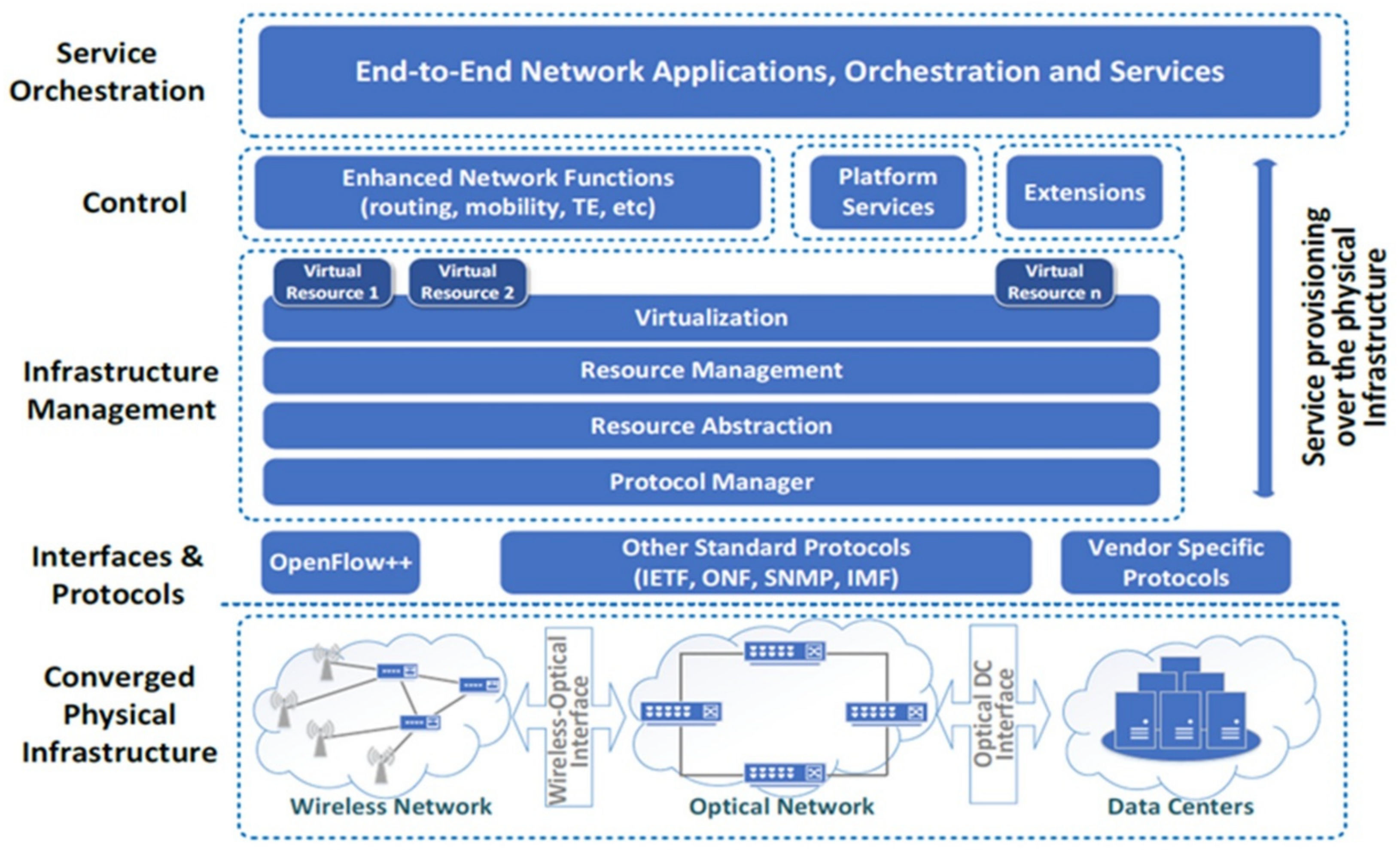
  • Develop a radically new architecture that will take a technology agnostic approach targeting cross-technology application, programmable infrastructure, and service composition driven by KPIs in, for example, capacity, connectivity, spectrum utilisation, energy efficiency, fairness, QoS, and QoE.
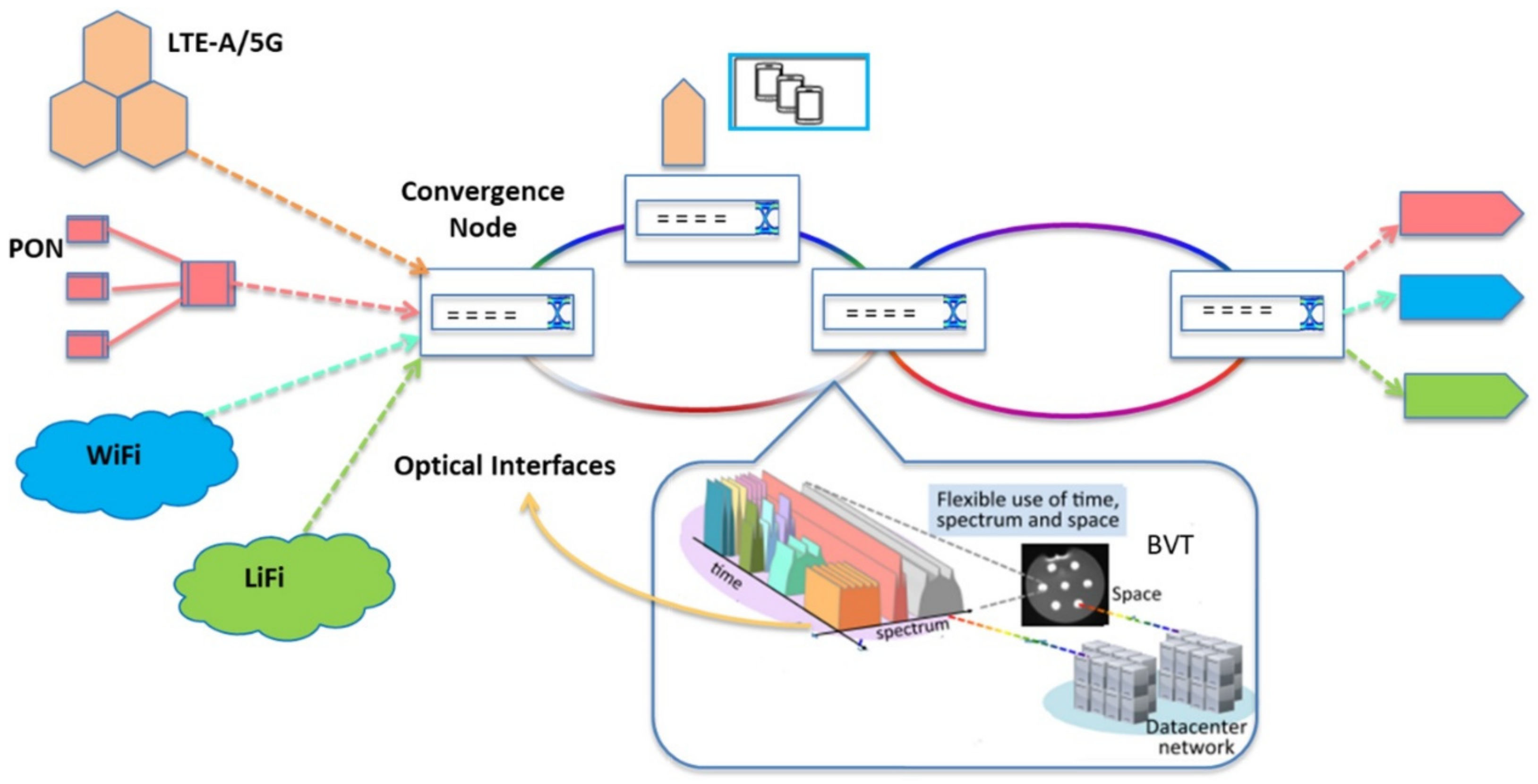
  • Converge heterogeneous technology domains seamlessly, specifically, wireless access and optical access, high capacity optical metro/backbone networks, data centre (DC) networks, and end devices.
  • Support very high bandwidth granularity range and capacity, from Pbps (e.g., inter-data centre transport) to kbps (e.g., machine-to-machine communications).
  • Break traditional barriers between infrastructure, control, and service layers by making the network infrastructure and its control part of the end-to-end service delivery chain.
Figure 2 illustrates the generic TOUCAN architecture. In this architecture, the TOUCAN converged physical infrastructure aims to design a generalised solution able to deliver agility, programmability, and flexibility for interfaces between heterogeneous transport technologies, that is, optical and wireless, and different networks—for example, optical core, metro and access; wireless cellular; and wireless local area networks. Figure 3 presents the architecture of the generic convergence-node with multiple interfaces to fulfil the TOUCAN-converged physical infrastructure illustrated in Figure 2. In this scenario, the node is implemented on field-programmable gate arrays (FPGAs) to provide the flexibility and the requests for future network convergence. In addition, the node interface takes advantage of the huge input–output (IO) resource and hardware programmability of FPGAs. Through high speed transceivers, the FPGA could process the incoming traffic from Ethernet, access, wireless cellular, and other networks. Then, the FPGA could use its computing power to perform traffic parsing, protocol framing/mapping, traffic aggregation, and other operations. Moreover, the convergence node aims to allocate resources elastically in time, spectrum, and space, in order to accommodate a large range of traffic profiles and granularities in an efficient way and providing low latency on the basis of considered vertical technology interfaces. Finally, the processed data traffic will drive different bandwidth variable transmitters (BVTs) to generate optical signals for transmission towards different networks.
The TSON solution [2,3] is a proprietary solution developed by the High Performance Networks (HPN) research group, currently part of Smart Internet Lab, University of Bristol, and has been adapted to support the convergence node proposed in Figure 3. This technology offers high bandwidth and low-latency connectivity to support the requirements of High-Performance Networks. The TSON solution is a proven active WDM solution that provides variable sub-wavelength switching granularity and the ability to dynamically allocate optical bandwidth elastically. This solution is the first multiple protocol programmable interface that meets 5G KPIs such as high bandwidth and sub-millisecond end-to-end latency [4].
Several extensions have been applied to the TSON architecture over the course of the TOUCAN project to equip this solution with more features. This work describes the TSON solution capabilities and reviews its evolution stages. The rest of the paper is structured as follows: Section 2 introduces the initial TSON solution implementations. In this section, we describe TSON extensions organised in four stages of evolution. Section 3 presents the current status of the TSON implementation. In this section, the latest TSON architecture is introduced and its evaluation results are presented. The TSON control plane is introduced in Section 4. Finally, Section 5 concludes the paper.

2. TSON, the Past

The TSON solution has evolved over the course of the TOUCAN project. Its evolution in the past comprised four stages: the TSON baseline solution, the multi-protocol solution in support of cloud radio access network (C-RAN), the extensions required for the support of resilient C-RAN services through network coding (NC) capabilities, and the extensions of TSON to support transmission capabilities for both metro and long-haul networks. This section reviews theses evolution stages.

2.1. Evolution Stage 1: TSON Baseline

The TSON idea was initiated by designing a multi-wavelength fully bi-directional synchronous and innovative flexible frame-based system [1,2]. It offers a flexible and multiplexed optical network infrastructure and on-demand guaranteed time-shared multi-granular services. This solution is a contentionless [5] solution through the deployment of a central resource allocation engine of route, wavelength, and time assignment, in charge of setting up the sub-wavelength paths.
TSON offers two type of nodes, edge and core nodes, offering different functionality and levels of complexity. The TSON edge nodes provide the interfaces between different domains, such as wireless, passive optical network (PON), and DC, to the optical domain and vice versa. Figure 4 presents the baseline of the TSON edge node data plane architecture. The architecture consists of one 10 Gb Ethernet client to send and receive data, and two 10 Gb wavelengths (lambdas). In this architecture, the ingress part of the edge node provides the aggregation and mapping, whereas the egress edge nodes include the reverse functionality. The TSON can support elastic time and optical bandwidth allocation. The ingress part waits to finish the processing of the current frame, and then starts to transmit time-slices on the basis of the optical bandwidth. The optical bandwidth allocated to the different services can be elastically defined on the basis of the requirements of each service.
The functionality of the ingress part of the edge node in detail is in receiving and passing the Ethernet frames to the 10 GE medium access control (MAC), then MAC discards the preambles and frame check sequence (FCS), transmits the data to the receiver (Rx) in a first in first out (FIFO) manner, and indicates whether the packet is status of the frame, that is, the frame is good or bad. The Rx FIFO receives the data, waits for the frame status indication from the MAC, and then sends it to demultiplexer (DEMUX) block when the data is valid. The role of DEMUX is to analyse the Ethernet frame information, that is, destination MAC address, source MAC address, and others, and dispatch them into different FIFOs. The FIFOs wait for the aggregation unit to grant access to send data. The aggregation unit grants access to the FIFO when the burst-length Ethernet frames are ready in the FIFO and the time-slice allocation is available, then it transmits the bursts with a suitable wavelength through the transmitter (Tx) FIFO. The egress part of the edge node receives a burst (time-slice) and passes it to the Rx FIFO wavelength (Lambda0/Lambda1). The segregation unit segregates the burst to Ethernet frames when the burst is completely received in Rx FIFO, and then transmits them to a Tx FIFO. Finally, Tx FIFO sends the Ethernet frames to the MAC, where the MAC passes the data to the transmitter before finally transmitting them out.
The TSON core node does not carry out any data processing. Instead, it needs to control the fast-optical switch in order to set up a path with a client’s request to switch the traffic optically. The core node demands one switch per wavelength to direct the incoming optical time-slice signals towards the output ports on the basis of the control plane definition. In addition, the dimension of the space switch is defined by the number of fibres that are interconnected through the node.
TSON supports two different functional modes: Ethernet and elastic bandwidth allocation mode. The Ethernet mode supports Ethernet-based packets without any time-slicing and elastic bandwidth allocation is based on time-slicing. The TSON control plane is presented in Section 4. It should be noted, however, that TSON is fully software defined networking (SDN) enabled. The parameters of TSON nodes are programmable by an SDN controller, including quality of transmission (QoT), programmable overhead, programmable time-slice size, programmable time-slice numbers in a frame, and time-slice allocation. The TSON is client friendly (e.g., operator, service provider). When required to setup a network service, after evaluating its requirements such as bit-rate, connectivity type, QoS, and QoT by the network controller, the TSON nodes choose the corresponding QoT overhead size, time-slice size, time-slice number, and time-slice allocation to fulfil such requests to compose a dedicated network function slice of the node. TSON provides a hierarchy of three levels of resource granularity:
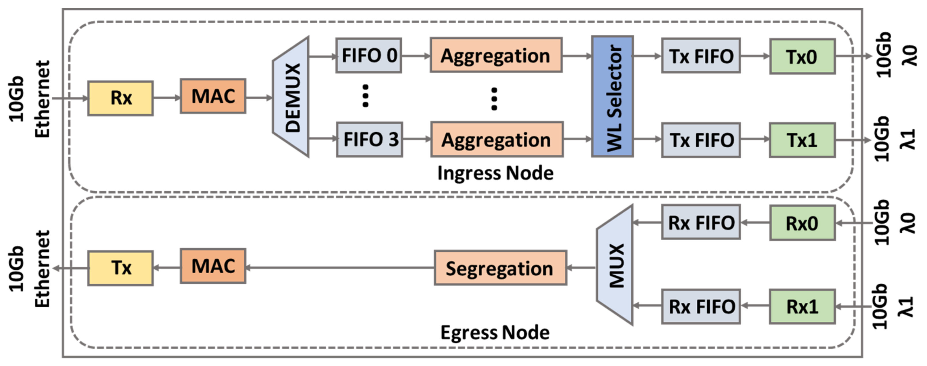
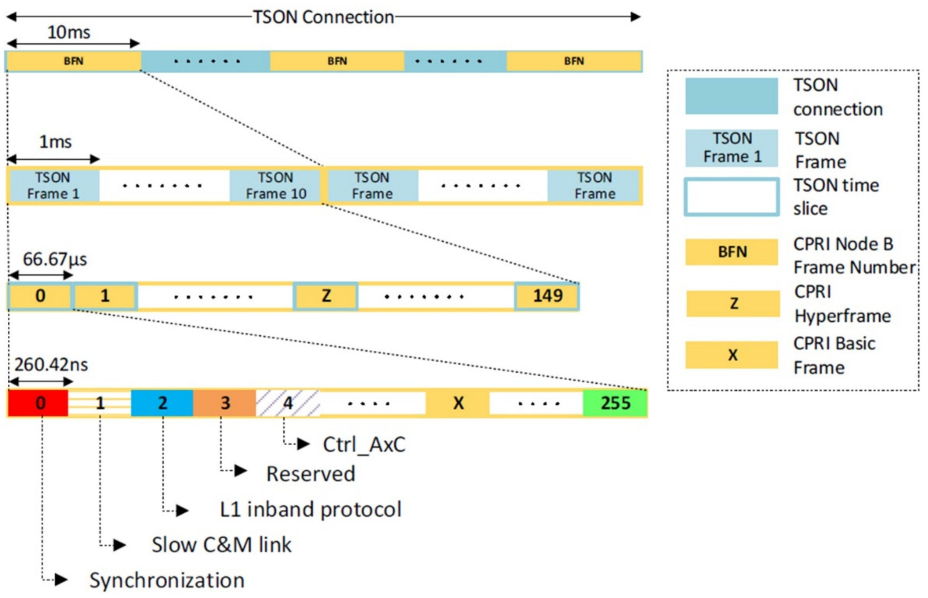
  • Connections—referring to a sub-wavelength light path establishment between any two end points in the TSON domain.
  • Frames—wherein each connection lasts for a number of frames to improve statistical multiplexing of data units.
  • Time-slices—wherein each frame is divided into time-slices as the smallest units of network resource.
The minimum granularity achievable by the TSON network is related to the frame length and the number of time-slices inside a frame. The TSON baseline implementation has been participated in several use cases [6,7,8].

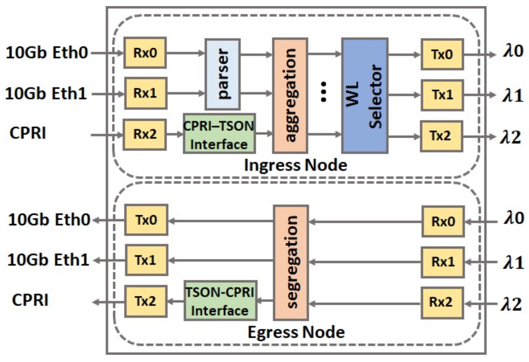
2.2. Evolution Stage 2: TSON Multi-Protocol

In the second evolution stage of the TSON solution, the TSON baseline technology has been extended to support multi-protocol, as well as to provide synchronisation capabilities. We have chosen xHaul as the multi-protocol scenario, which is joined Backhaul (BH) and Fronthaul (FH) services. The reason to choose xHaul scenario is that the TSON can support varying service-related requirements as its operational characteristics can be dynamically modified. Therefore, multiple Ethernet clients for BH as well as CPRI integration for FH services are considered. The TSON client ports extension are only limited to the number of available transceivers on FPGA boards, as well as the FPGA density to support extended architecture.
Figure 5 illustrates the TSON edge node to support multi-protocol data plane architecture. This architecture follows the TSON baseline legacy with the following extra features:
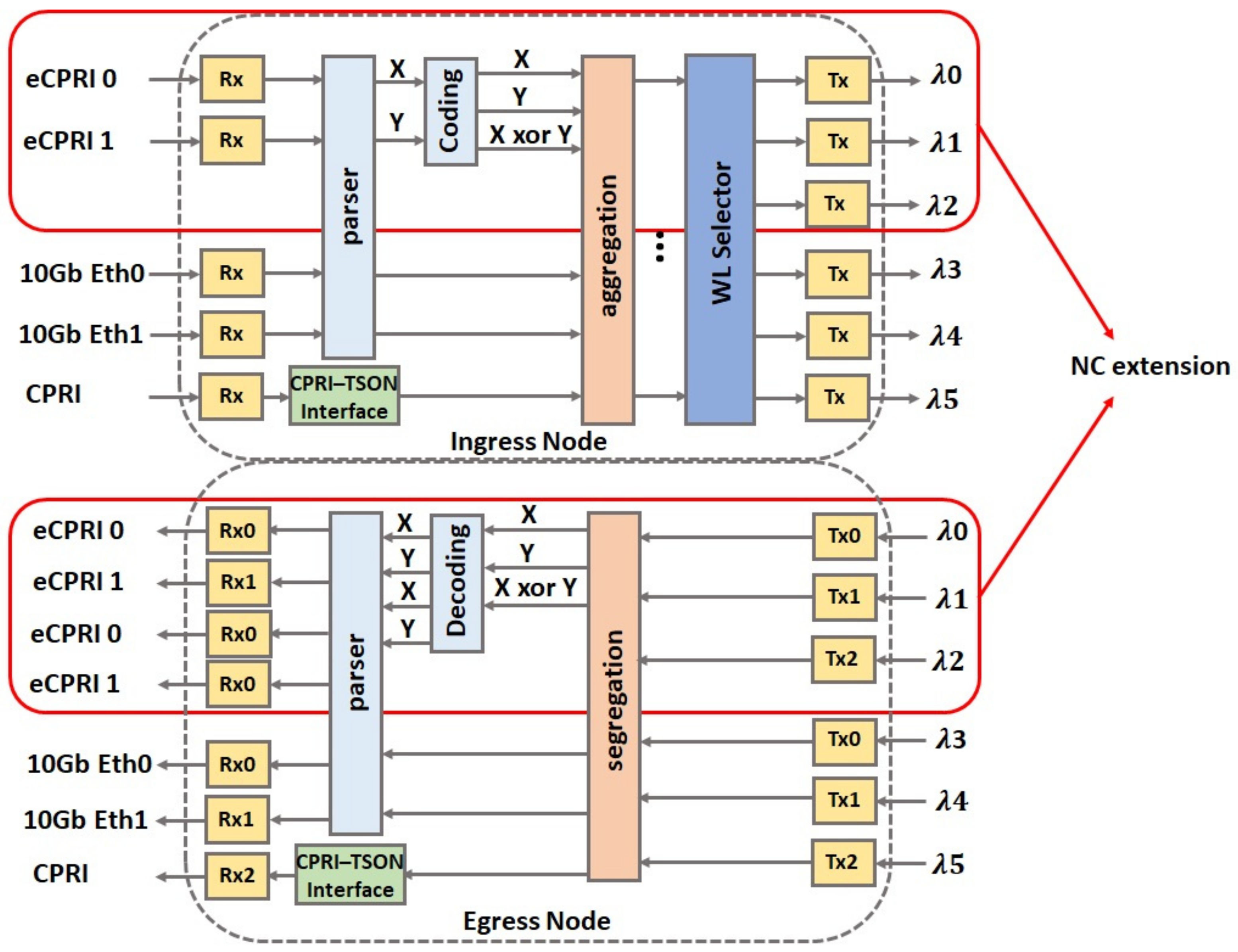
  • Supporting xHaul—the TSON Ethernet client ports are extended to multi-ports supporting BH services and native CPRI is added to support FH for the xHaul solution.
  • Wavelength multiplexing—the clients can use a common wavelength (i.e., lambda) if the total bandwidth of the client is less than 10 Gb. In this scenario, the frames are delivered to the related clients at the egress nodes on the basis of their header information.
  • Synchronisation—IEEE-1588 v2 [9] protocol is integrated for accurate synchronisation.
In this architecture, the CPRI transceiver receives the CPRI frames and passes them to the CPRI_TSON interface unit in the ingress side. The CPRI_TSON interface is responsible for the clock domain crossing (CDC) and the mapping of the CPRI data and control to TSON format. Once the CPRI frames reach the aggregation block, then, according to the look-up table (LUT) information of the time-slice allocation, the aggregation block calculates the frames needed to construct the burst, aggregates the frames, waits for the valid time-slice, and finally sends the burst into a different wavelength. The egress side has the reverse functionality. Figure 6 presents how a CPRI flow can be embedded into the TSON framing structure.
High synchronisation accuracy over the network requires an accurate time-stamping method. The TSON network requires global frame synchronisation among TSON nodes to achieve high synchronisation accuracy over the network. We have adopted IEEE-1588-v2 protocol for the TSON solution. Xilinx 10 Gb Ethernet Subsystem IP core [10] supports high accuracy IEEE-1588-v2 one-step and two-step time-stamping on a 10GBASE-R network interface, but does not support multiple IEEE-1588-v2-enabled subsystem instances [11]. To resolve this issue, a new subsystem has been developed to support multiple IEEE-1588-v2 enabled subsystems. The Xilinx approach uses time stamper unit for the transmit-side and the receiver-side inside the MAC and the physical coding sublayer/ physical media attachment (PCS/PMA) sub intellectual property (IP) cores, respectively. Unlike the Xilinx approach, the developed subsystem uses a separate developed time stamper. Figure 7 shows the proposed subsystem architecture. The developed time stamper follows the same features as the Xilinx Subsystem. The time stamper unit is located between the MAC and PCS/PMA IP cores, uses the Timer Syns clock, and follows the IEEE-1588-v2 protocol. In addition, the time stamper considers the physical layer delay for stamping.
The architecture supporting multi-protocol is evaluated [4] and employed in an end-to-end use case demo [12]. Video S1 demonstrates the multi-protocol TSON extension to address the varying FH capabilities needed by the different remote radio heads (RRHs) and BH requirements.

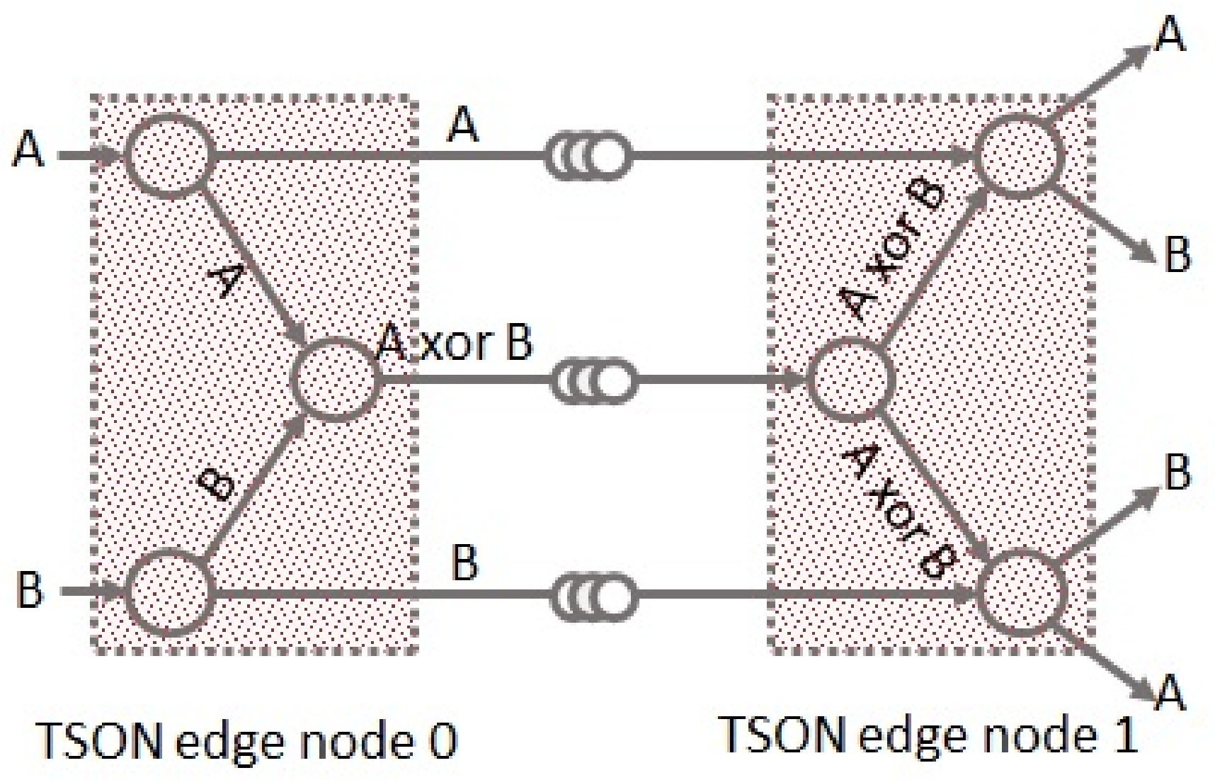
2.3. Evolution Stage 3: TSON NC for Resilient C-RANs

The third stage of the TSON evolution enables TSON to support NC for resilient C-RANs. The goal is to protect the bandwidth demanding C-RAN services from possible optical network and/or baseband unit (BBU) failures. The NC-based approach is developed to tackle the issue with increased resource efficiency. A reduction in utilisation of 33% has been identified when using the NC approach compared to the traditional 1 + 1 protection scheme. However, in order to adopt NC-based resilient FH networks there are three main challenges:
  • Coding—providing module-2 sum and replication operation at FH line rate, as these factors may degrade the performance of C-RANs in practical systems.
  • Storage—the operation of the decoding process at the edge imposes significant buffering requirements due to the high data rate of FH streams.
  • Synchronisation—synchronisation between flows reaching decode nodes.
TSON is extended [13] to address these challenges and execute the coding and decoding processes at line rate, as well as minimising buffering requirements adopting a purposely developed synchronisation scheme to make it suitable for C-RAN implementation. We considered a butterfly network for NC. Figure 8 presents the butterfly network consisting of two TSON nodes. In this scenario, each TSON node maps three source nodes of a butterfly network for NC. The TSON node 0 receives two different FH traffic streams (A and B) and sends the streams A, B, and their modulo 2 sum (XOR) of both traffic streams to the TSON node 1. The TSON node 1 receives the three traffic streams and transmits each traffic stream A and B simultaneously to two destinations of the TSON node 1.
Figure 9 presents the TSON data plane architecture with extra pipelines to support NC for FH considering the butterfly network. The marked extended pipelines in the figure follow the other TSON pipelines legacy with extra coding/decoding capability. In the ingress node of these pipelines, the incoming traffic parses to two flows: X and Y. The output ingress node contains three different wavelengths (X, Y, and X XOR Y) that can be configured on the fly using SDN to address different programmable parameters. The egress edge nodes include the reverse functionality with extra replication outputs to support a butterfly network. The IEEE-1588-v2 synchronisation is employed for accurate synchronisation. The TSON architecture supporting NC is presented and evaluated in [13].

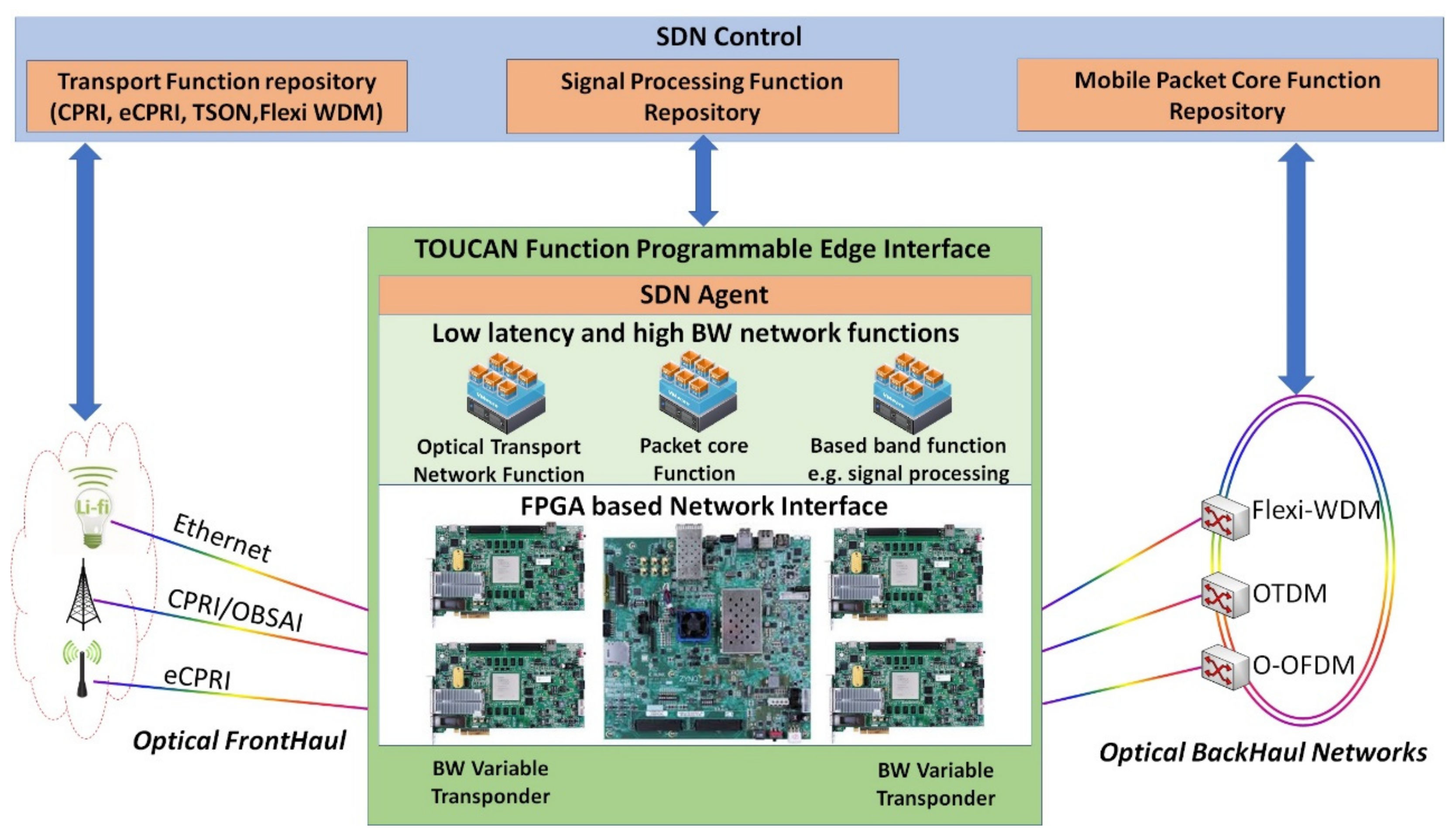
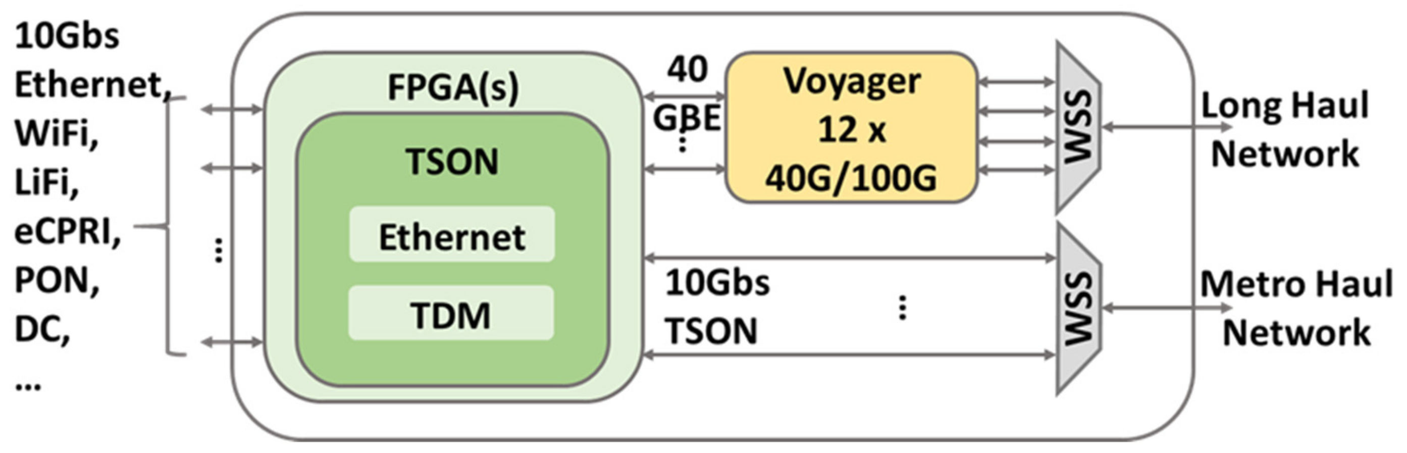
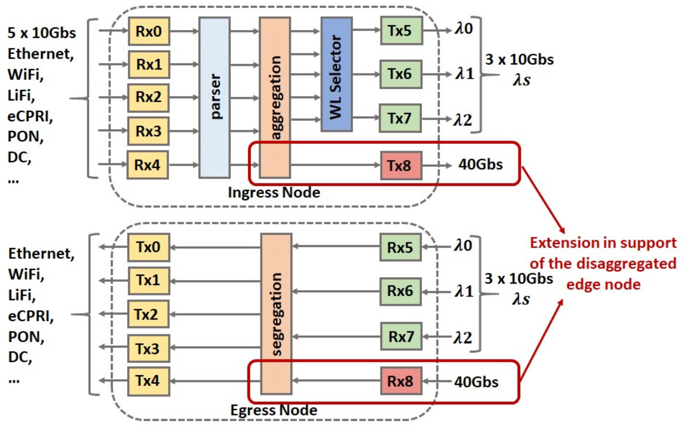
2.4. Evolution Stage 4: TSON Multi Haul

The fourth stage of the TSON evolution is building a state-of-the-art disaggregated edge node to support both metro and long-haul networks [14]. The reason behind creating such a disaggregated edge node for the first time is the need for a flexible and programmable edge node architecture providing an interface between the 5G access and transport network. This requirement is due to the plethora of applications, their KPIs, and the diversity of 5G access network technologies that will share common transport network solutions.
Figure 10 presents the proposed disaggregated edge node data plane architecture comprising the TSON solution, Voyager [15], and wavelength selective switches (WSS) [16]. This architecture is highly programmable using SDN. As the heart of the architecture, the TSON solution follows the TSON multi-protocol legacy presented in the previous sub-section, as well as supporting both metro and long-haul networks on demand on the basis of the operator or service provider requirements. The TSON edge node aggregates/dis-aggregates any input access traffic to/from a highly synchronous and bandwidth granular optical transport on the basis of time slot switching in a programmable way. In addition, it provides access to a highly programmable coherent variable bandwidth transponder suitable for spectrally elastic long-haul transmission. The Voyager is a Broadcom Tomahawk-based switch with added dense wavelength division multiplexing (DWDM) ports, acting as a disaggregated optical transponder [14]. It hosts multiple BVTs that are capable of dynamically allocating variable spectral width and reach by modifying the device parameters. This is achieved through the support of three types of modulation formats, namely polarisation multiplexed quadrature phase-shift keying (PM-QPSK), 8-ary quadrature-amplitude modulation (8-QAM), and 16-ary quadrature-amplitude modulation (16-QAM) that allow different line rates of up to 200 Gbps. The WSS provides filtering and switching of the optical signal [15]. The WSS is used in this architecture as a programmable 4 × 16 optical switch that multiplexes and demultiplexes the optical signals to specific ports. As can be seen in Figure 10, one WSS is connected to the Voyager and another to the TSON output ports. WSS’multiplex and demultiplex four wavelengths with different bandwidths from the Voyager/TSON ports.
Figure 11 presents the TSON data plane architecture in support of the disaggregated edge node. The functions for the operation of TSON domains has been implemented in internal modules, within the SDN controller, which collaborate for the on-demand provisioning of connectivity between TSON nodes. The data plane functionality of this architecture is the same as the previous architecture. The 10 Gbs wavelengths are dedicated for metro networks. The extended pipelines with 40 Gbs, which are marked in Figure 11, are to support long-haul networks with only Ethernet mode. In the extension scenario, the ingress TSON edge nodes are responsible for parsing, aggregation, and mapping of any input traffic combination with different bandwidth into converged 40 Gbps Ethernet output, whereas the egress edge nodes have the reverse functionality. The disaggregated edge nodes are evaluated at the same time for both 8 km metro and 200 km long-haul networks and the evaluation results are available in [14]. Results showed that low latency and power penalty for both metro and long-haul networks.

3. TSON, Present

This section presents the fifth evolution stage, this being the current architecture of the TSON solution. The current architecture maintains all previous features of the TSON and adds more functionality and flexibility to it. In addition, the architecture is implemented, tested, and evaluated over a real testbed.

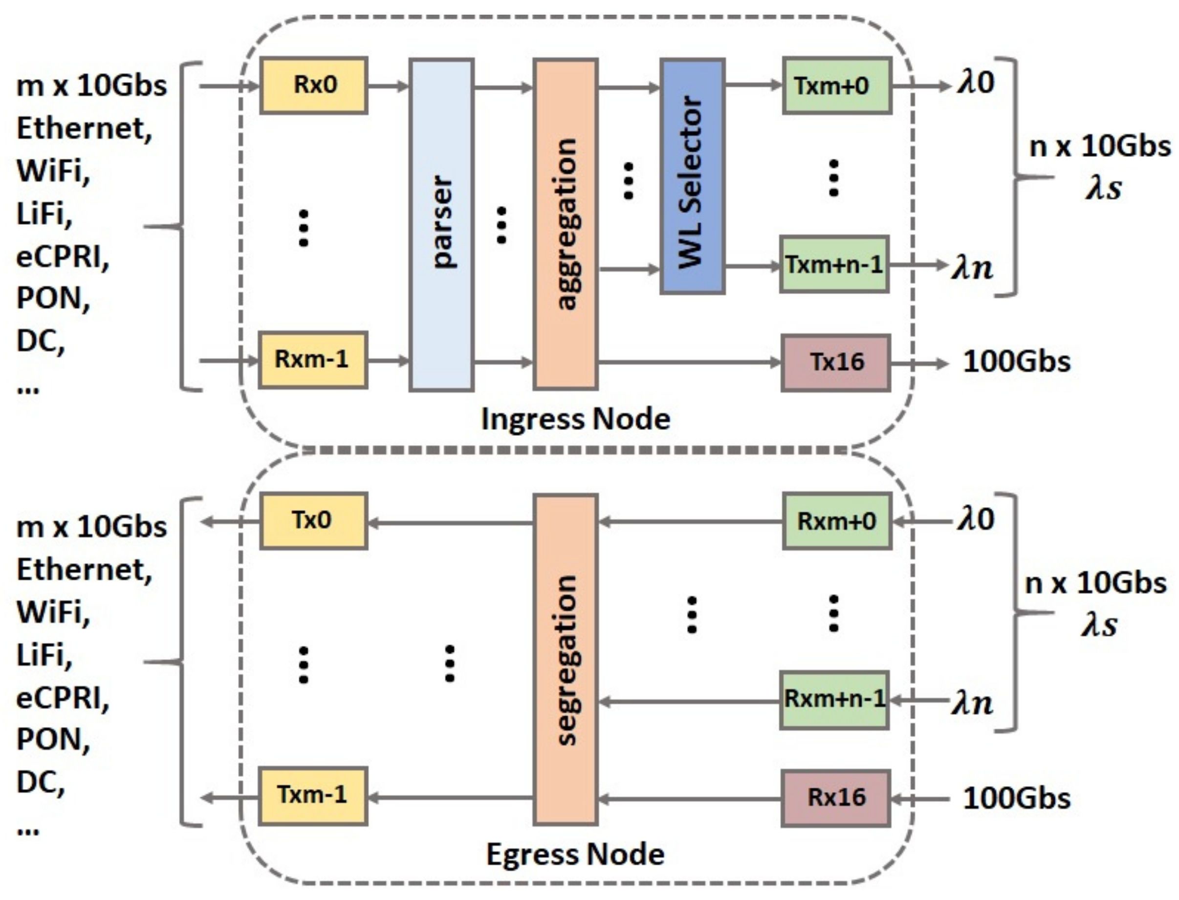
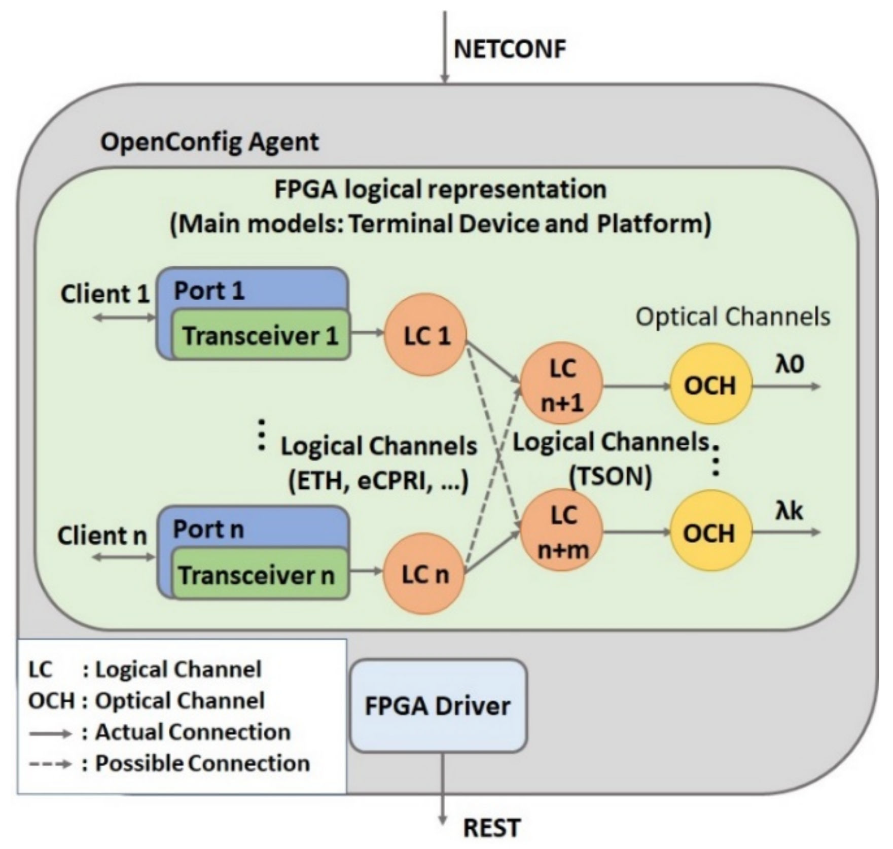
3.1. Evolution Stage 5: Current TSON Architecture

Figure 12 presents the current TSON edge node data plane architecture. The ingress TSON edge nodes are responsible for parsing, aggregation, and mapping of any input traffic combination with different bandwidths (in this implementation less than 10 Gbps) into either 10 Gbps TSON output with different granularity or converged 100 Gbps Ethernet output, whereas the egress edge nodes have the reverse functionality. As it can be seen in Figure 12, the architecture is similar to the pervious TSON solution architecture.
Although this architecture carries out the previous features, it adds more values to the TSON solution. Seven new TSON solution features in the current implementation are as follows:
  • Modularity—a set of intellectual property (IP) cores have been created to ease and shape the TSON system integration.
  • Extendibility—the TSON pipelines are designed to be extendable. The only limitation factor is the FPGA chip density and IOs for implementation.
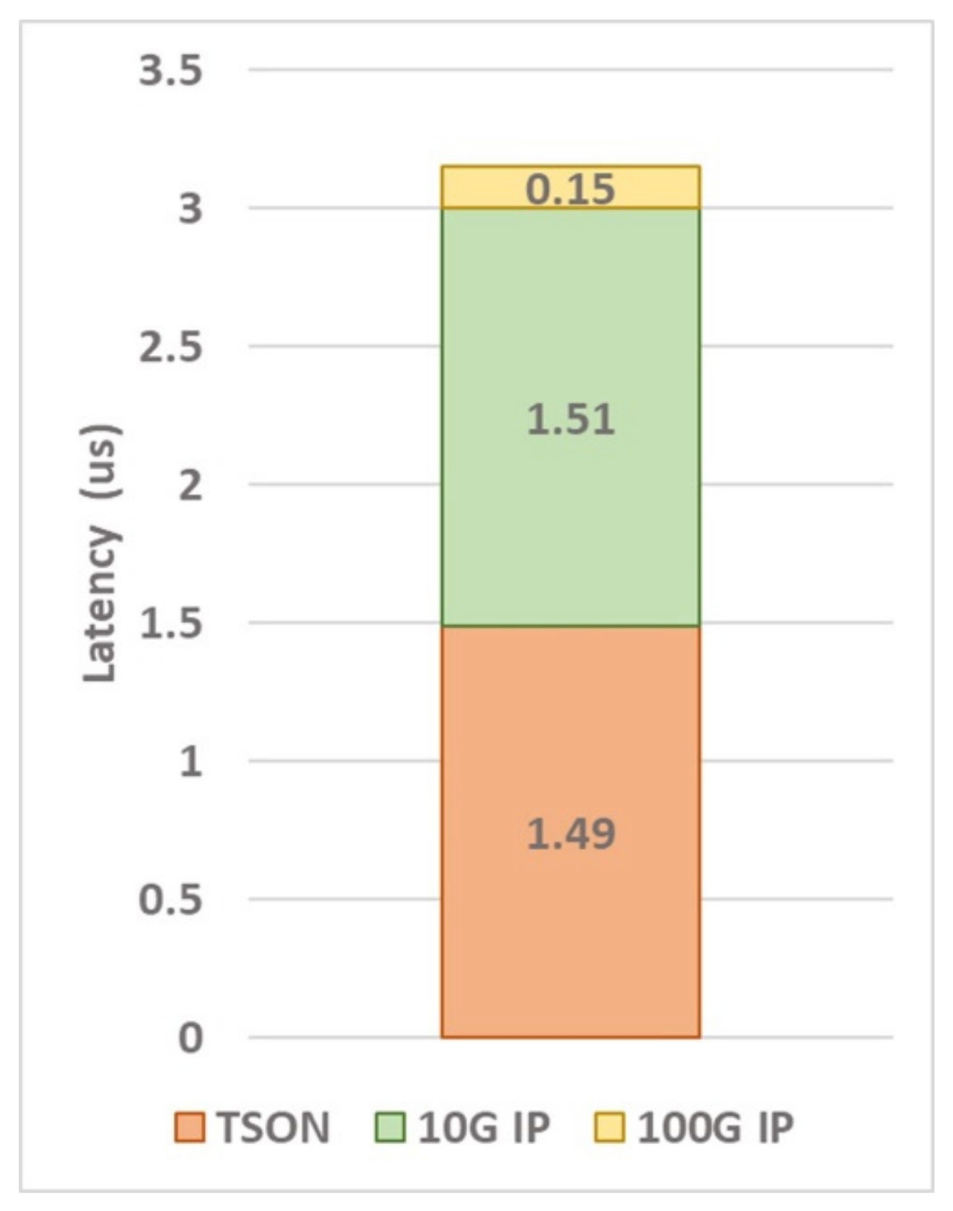
  • Optimisation—the TSON pipelines are optimised to reach lower latency for 10 Gb pipelines and reduce the latency by 6.7%.
  • 100 Gb aggregation—× 10 Gb to 100 Gb aggregation is added to the design.
  • Frame format—the TSON frame format is changed. In this scenario, each TSON frame slice carries the incoming client frame format. This means if the client data is Ethernet packets, the TSON frame slices are shaped by Ethernet frames. This feature makes the TSON frames transparent for other packet processing devices, but the time-slices frames are visible for them for processing.
  • Symmetry—each 10 Gb line can be used as client or lambda, depending on the demands without changing anything in the hardware if m + n − 1 = number of 10 G IOs, where m is the number of clients and n is the number of lambdas. This feature is another result of the changing TSON frame format.
  • Elastic bandwidth allocation mode—this mode is enabled for both 10 Gb and 100 Gb wavelengths.

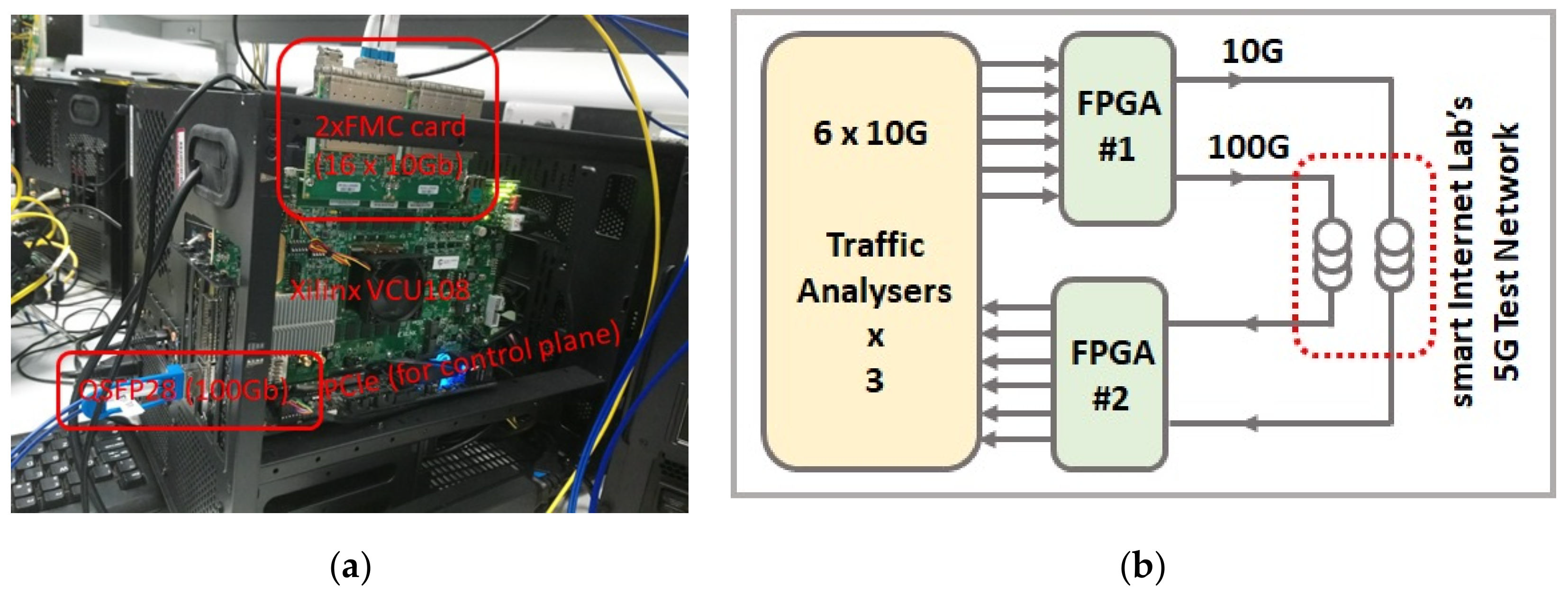
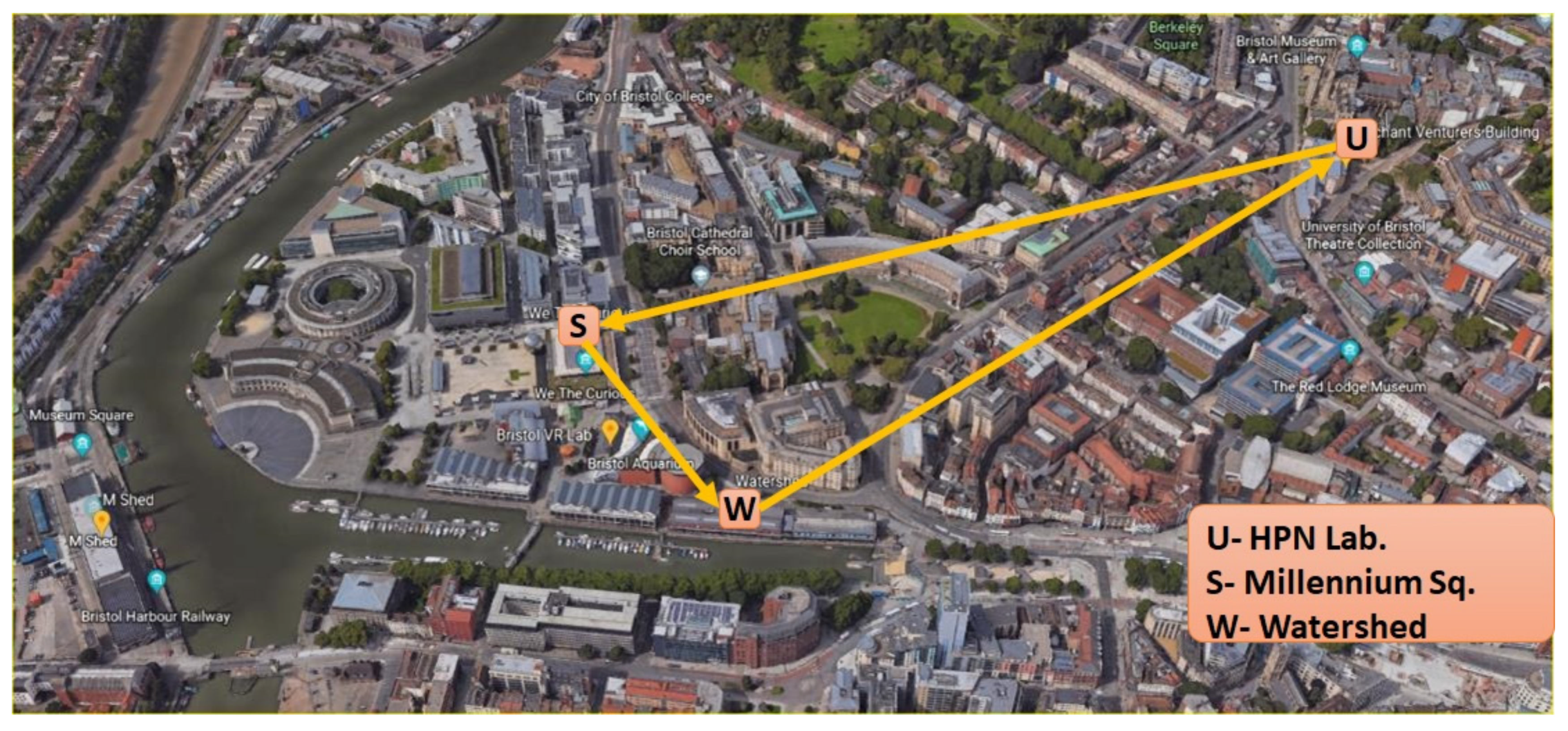
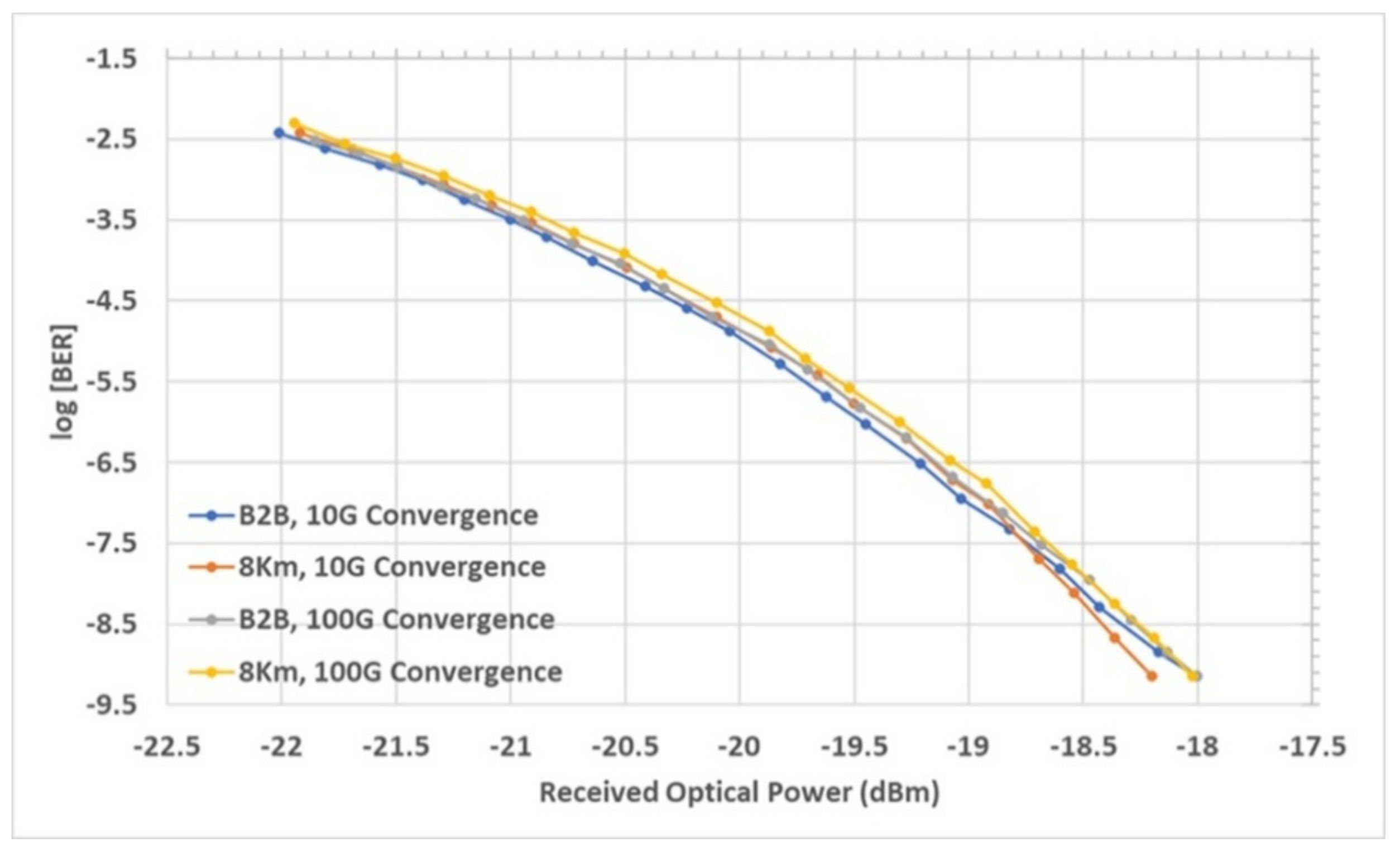
3.2. The TSON Testbed Setup and Experimental Results

Xilinx vcu108 evaluation board is employed for this implementation. Figure 13a shows the TSON edge node, which is a Xilinx FPGA board connected to a server and receiving the SDN control plane command via peripheral component interconnect express (PCIe). The FPGA board is connected to two FPGA mezzanine cards (FMCs) to provide 16 × 10 Gb (m + n − 1 = 16) IOs. Figure 13b shows the testbed setup architecture with two TSON edge nodes. The edge nodes are connected to 6 × 10 Gbps ethernet traffic analysers from one side and from the other side to Smart Internet Lab’s 5G test network. The 10 Gbps traffic streams can be aggregated to 10 or 100 Gbps traffic that is both sent to the metro network on the basis of different control policies.
The Smart Internet Lab’s 5G test network (5GUK test network) has its core in the HPN lab at the University of Bristol. The test network serves several nodes in Bristol, as well as the Roman Baths in city of Bath, in providing access points for end user terminals connectivity for experimentation. Figure 14 presents the 5GUK test network locations we have used to make a ring topology for the evaluation scenarios. Note that the ring topology is approximately 8 km.
We have validated the functionality of the TSON edge nodes by applying different control policies on the fly using the SDN controller for both aggregated 10 and 100 Gb lines at the same time. Two different scenarios were considered for the experimental evaluation of the edge nodes. The first scenario involved back-to-back connection of two TSON edge nodes with standard single mode fibre (SSMF). In the second scenario, the proposed nodes were evaluated over the 5GUK test network with 8 km of optical fibre. We evaluated the nodes using a fixed frame of 1500 B length. We used fine granularity to evaluate the edge nodes. In the fine granularity case, the TSON packet size was the same as the Ethernet frames, that is, 1500 B in length. For the sake of performance analysis, one 4 Gb and one 4.5 Gb client frames were converged to a 10 Gb line. Four 9.8 Gb clients were converged to a 100 Gb line. The Ethernet performance parameters under consideration included bit error rate (BER) and latency. Latency is defined as the time difference between the arrival of a frame at the analyser, and its departure from the analyser.
Table 1 presents the latencies for the mentioned scenarios. This table shows that each TSON convergence node took 4.43 and 3.16 µs for 10 Gb convergence and 100 Gb convergence, respectively. The back-to-back latency was 8.86 µs for 10 G convergence, which was 2.54 µs more than 100 G convergence. Further measurements have been taken to find out the reason. An edge node consists of 10 Gb IP cores, TSON pipelines, and 100 Gb IP core. We have measured the latency for individual components. Figure 15 shows the measurement result for 100 G convergence. In this scenario, frames passed one 10Gb IP core, TSON pipelines, and one 100 Gb IP core. As can be seen in Figure 15, the TSON pipelines’ latency was approximately the same as the 10 Gb IP core, and the 100Gb IP core latency was much less than the 10 Gb IP core. The TSON pipelines’ latency was approximately 1.5 µs, which is very low. Figure 16 shows the BER for the evaluation scenarios. As it can be seen in this figure, the penalty was negligible for both 10 and 100 Gb convergence scenarios.

4. TSON Control Plane

This section overviews the TSON control plane. The TSON is fully software defined networking (SDN) enabled [17]. ONOS controller has been used as an SDN controller, wherein some applications or modules have been extended or developed. The TSON control plane architecture is depicted in Figure 17. It comprises an ONOS SDN controller where the OpenConfig driver is extended in order to handle the TSON features. Also, the NETCONF/OpenConfig agent based on the extended OpenConfig has been developed. This agent receives the request from the SDN controller via NETCONF in order to configure the FPGA. The developed NETCONF agent can process the received request and configure the TSON device implemented by an FPGA.
OpenConfig is used to represent the TSON device. Indeed, the standard OpenConfig YANG model does not handle all the TSON features and needs to be extended. The OpenConfig YANG model implements several modules. Logical channel of the terminal device module has been extended to control the TSON parameters, such as:
  • Virtual local area network (VLAN) pairs;
  • Time slots size;
  • Frames size;
  • Mode of transmission (TSON or Ethernet) to select the granularity.
Figure 18 depicts the logical representation of the OpenConfig agent, wherein several clients (depending on the TSON device implementation) and two outputs are shown. The OpenConfig agent can configure the transmission mode (Ethernet or TSON) to configure the TSON parameters (if this mode of transmission is selected) or multiplex/demultiplex the logical ingress channels on one of the optical channels. Also, an FPGA driver is developed in order to send the parameters to the FPGA agent via REST API.

5. Conclusions

We proposed the TSON in order to provide a dynamic optical transport solution in support of 5G technology and beyond. The TSON solution has been adapted and evolved over the course of the TOUCAN project. This work presents the evaluation stages. We started with the TSON baseline stage, focusing on the TSON solution idea, its architecture, and functionality. TSON baseline only supports one client with Ethernet protocol; therefore, we have extended it to support multi-protocol with multi clients. xHaul, as the multi-protocol scenario, was chosen for this extension, and synchronisation capabilities were added to the TSON. Then, the TSON was extended to support NC for resilient C-RANs for the sake of 33% reduction in utilisation. The goal of the next evolutionary step is creating a disaggregated edge node to support both metro and long-haul networks. Finally, the current TSON architecture was presented and evaluated using the 5GUK test network. The evaluation results denote the reliability of the TSON solution over dark fibres.

Supplementary Materials

The following are available online at https://www.youtube.com/watch?v=FtGxYhiNO_g: Video S1: Programmable multi-technology 5G node.

Author Contributions

Conceptualisation, A.F.B., A.T., R.N. and D.S.; methodology, A.F.B., A.T. and R.N.; software, A.F.B.; validation, A.F.B.; formal analysis, A.F.B.; investigation, A.F.B.; resources, A.F.B., A.T. and R.N.; data curation, A.F.B., A.T. and R.N.; writing—original draft preparation, A.F.B.; writing—review and editing, A.F.B., A.T. and R.N.; visualization, A.F.B.; supervision, D.S.; project administration, D.S.; funding acquisition, D.S.

Funding

This research was funded by the U.K. Engineering and Physical Sciences Research Council (EPSRC), grant number EP/L020009/1, TOUCAN.

Conflicts of Interest

The authors declare no conflict of interest. The funders had no role in the design of the study; in the collection, analyses, or interpretation of data; in the writing of the manuscript, or in the decision to publish the results.

References

  1. TOUCAN Project Website. Available online: https://www.toucan-network.ac.uk/ (accessed on 30 August 2019).
  2. Zervas, G.S.; Triay, J.; Amaya, N.; Qin, Y.; Cervelló-Pastor, C.; Simeonidou, D. Time Shared Optical Net-work (TSON): A novel metro architecture for flexible multi-granular services. Opt. Express 2011, 19, B509–B514. [Google Scholar] [CrossRef] [PubMed]
  3. Yan, Y.; Qin, Y.; Zervas, G.; Rofoee, B.; Simeonidou, D. High performance and flexible FPGA-based time shared optical network (TSON) metro node. Opt. Express 2013, 21, 5499–5504. [Google Scholar] [CrossRef] [PubMed]
  4. Farhadi-Beldachi, A.; Huques-Satas, E.; Tzanakaki, A.; Yan, Y.; Nejabati, R.; Simeonidou, D. Experimental Demonstration of 5G Fronthaul and Backhaul Convergence based on FPGA based Active Optical Transport. In Proceedings of the 2018 European Conference on Optical Communication (ECOC), Rome, Italy, 23–27 September 2018. [Google Scholar]
  5. Kozdrowski, S.; Zotkiewicz, M.; Sujecki, S. Optimization of Optical Networks Based on CDC-ROADM Technology. Appl. Sci. 2019, 9, 399. [Google Scholar] [CrossRef]
  6. Jackson, C.; Kondepu, K.; Ou, Y.; Farhadi Beldachi, A.; Pagès Cruz, A.; Agraz, F.; Moscatelli, F.; Miao, W.; Kamchevska, V.; Calabretta, N.; et al. COSIGN: A complete SDN enabled all-optical architecture for data centre virtualisation with time and space multiplexing. In Proceedings of the European Conference and Exhibition on Optical Communication, Gothenburg, Sweden, 27–21 September 2017. [Google Scholar]
  7. Kondepu, K.; Zou, J.; Farhadi Beldachi, A.; Chen, H.K.; Chase, C.; Huang, M.; Hugues Salas, E.; Garcia-Espin, J.A.; Tzanakaki, A.; Nejabati, R.; et al. Performance Evaluation of Next-Generation Elastic Backhaul with Flexible VCSEL-based WDM Fronthaul. In Proceedings of the European Conference and Exhibition on Optical Communication, Gothenburg, Sweden, 27–21 September 2017. [Google Scholar] [CrossRef]
  8. Kondepu, K.; Jackson, C.; Ou, Y.; Beldachi, A.; Pagès, A.; Agraz, F.; Moscatelli, F.; Miao, W.; Kamchevska, V.; Calabretta, N.; et al. Fully SDN-enabled all-optical architecture for data center virtualization with time and space multiplexing. IEEE J. Opt. Commun. Netw. 2018, 10, B90–B101. [Google Scholar] [CrossRef]
  9. IEEE Standard for a Precision Clock Synchronization Protocol for Networked Measurement and Control Systems; IEEE Std 1588–2008 (Revision of IEEE Std 1588–2002); IEEE: Piscataway, NJ, USA, 2008; Volume 1, pp. 1–269.
  10. Available online: https://www.xilinx.com/products/intellectual-property/axi_10g_ethernet.html (accessed on 6 November 2019).
  11. Available online: https://www.xilinx.com/support/documentation/ip_documentation/axi_10g_ethernet/v3_1/pg157-axi-10g-ethernet.pdf (accessed on 6 November 2019).
  12. Camps Mur, D.; Gutierrez, J.; Tzanakaki, A.; Flegkas, P.; Choumas, K.; Giatsios, D.; Farhadi Beldachi, A.; Diallo, T.; Zou, J.; Legg, P.; et al. 5G-XHaul: A Novel Wireless-Optical SDN Transport Network to Support Joint 5G Backhaul and Fronthaul Services. IEEE Commun. Mag. 2019, 57, 99–105. [Google Scholar] [CrossRef]
  13. Farhadi Beldachi, A.; Anastasopoulos, M.; Manolopoulos, A.; Tzanakaki, A.; Nejabati, R.; Simeonidou, D. Resilient Cloud-RANs Adopting Network Coding. In Proceedings of the 23rd International Conference on Optical Network Design and Modeling (ONDM 2019), Athens, Greece, 13 May 2019. [Google Scholar]
  14. Farhadi Beldachi, A.; Diallo, T.; Rajkumar, K.; Hugues Salas, E.; Wang, R.; Tzanakaki, A.; Nejabati, R.; Simeonidou, D. A Novel programmable disaggregated edgenode supporting heterogeneous 5g access technologies. In Proceedings of the 45th European Conference on Optical Communication, Dublin, Ireland, 22–26 September 2019. [Google Scholar]
  15. Facebook Voyager Optical Interfaces. Available online: https://docs.cumulusnetworks.com/display/DOCS/Facebook+Voyager+Optical+Interfaces (accessed on 14 April 2019).
  16. WaveShaper 1600A. Available online: https://www.finisar.com (accessed on 14 April 2019).
  17. Diallo, T.; Beldachi, A.F.; Muqaddas, A.S.; Silva, R.; Nejabati, R.; Tzanakaki, A.; Simeonidou, D. Enabling Heterogenous Low Latency and High-bandwidth Virtual Network Services for 5G Utilizing a Flexible Optical Transport Network. In Proceedings of the 2019 Optical Fiber Communications Conference and Exhibition, San Diego, CA, USA, 3–7 March 2019. [Google Scholar]
Figure 1. A high-level architecture of the Towards Ultimate Convergence of All Networks (TOUCAN) interface. SDN: software defined networking, CPRI: common public radio interface, eCPRI: evolved common public radio interface, TSON: time shared optical network, Flexi WDM: flexi-wavelength division multiplexing, BW: bandwidth, OBSAI: open base station architecture initiative, OTDM: optical time domain multiplexing, O-OFDM: optical orthogonal frequency-division multiplexing.
Applsci 09 04786 g001
Figure 2. The generic TOUCAN architecture. TE: traffic engineering, IETF: internet engineering task force, ONF: open networking foundation, SNMP: simple network management protocol, IMF: internet message format.
Applsci 09 04786 g002
Figure 3. The generic convergence-node architecture. LTE-A: long term evolution advanced, PON: passive optical network, WiFi: wireless fidelity, LiFi: light fidelity, BVT: bandwidth variable transponder.
Applsci 09 04786 g003
Figure 4. The time shared optical network (TSON) edge node baseline data plane architecture. Rx: receiver, Tx: transmitter, MAC: medium access control, FIFO: first in first out, WL: wavelength, MUX: multiplexer, DEMUX: demultiplexer.
Applsci 09 04786 g004
Figure 5. TSON edge node multi-protocol data plane architecture. Rx: receiver, Tx: transmitter, WL: wavelength, CPRI: common public radio interface, TSON: time shared optical network.
Applsci 09 04786 g005
Figure 6. Common public radio interface (CPRI) frame structure over TSON. C&M: control and management, L1: layer 1, Ctrl_AxC: control data stream for antenna carrier, BFN: node B frame number.
Applsci 09 04786 g006
Figure 7. Proposed subsystem for synchronisation. AXI4: advanced eXtensible interface 4, MAC: medium access control, PCS/PMA: physical coding sublayer/physical media attachment, XGMII: 10 gigabit media independent interface.
Applsci 09 04786 g007
Figure 8. Butterfly network for network coding (NC) and its mapping on TSON edge nodes.
Applsci 09 04786 g008
Figure 9. The TSON data plane architecture supporting NC.
Applsci 09 04786 g009
Figure 10. The disaggregated edge node data plane architecture. WiFi: wireless fidelity, LiFi: light fidelity, eCPRI: evolved common public radio interface, PON: passive optical network, DC: data centre, WSS: wavelength selective switches.
Applsci 09 04786 g010
Figure 11. The TSON solution data plane architecture in support of the disaggregated edge node.
Applsci 09 04786 g011
Figure 12. The TSON edge node current data plane architecture. m + n − 1 = number of 10 G input–outputs (IOs).
Applsci 09 04786 g012
Figure 13. Testbed setup: (a) TSON edge node; (b) the TSON edge nodes testbed setup architecture.
Applsci 09 04786 g013
Figure 14. The Smart Internet Lab’s 5G test network (5GUK test network) ring topology to evaluate the TSON edge nodes. HPN: High Performance Networks.
Applsci 09 04786 g014
Figure 15. Performance evaluation: latency for one TSON edge node components. IP: intellectual property.
Applsci 09 04786 g015
Figure 16. Performance evaluation: bit error rate (BER) for different evaluation scenarios. B2B: back to back.
Applsci 09 04786 g016
Figure 17. The TSON control plane architecture. FPGA: field-programmable gate array. SDN: software-defined networking, NETCONF: network configuration protocol, TDM: time domain multiplexing.
Applsci 09 04786 g017
Figure 18. Logical representation of the TSON node based on OpenConfig. OCH: optical channel, LC: logical channels.
Applsci 09 04786 g018
Table 1. Latency for different test scenarios.
DestinationLatency (µs)
Back to back, 10 G convergence8.86
Back to back, 100 G convergence6.32
8 km, 10 G convergence47.6
8 km, 100 G convergence45.1

