Article

Energy-Efficient Hybrid Beamforming with Variable and Constant Phase Shifters

by
Godwin Mruma Gadiel
1 and
Kyungchun Lee
2,*
1
Department of Electrical and Information Engineering, Seoul National University of Science and Technology, 232 Gongneung-ro, Nowon-gu, Seoul 01811, Korea
2
Department of Electrical and Information Engineering and Research Center for Electrical and Information Technology, Seoul National University of Science and Technology, 232 Gongneung-ro, Nowon-gu, Seoul 01811, Korea
*
Author to whom correspondence should be addressed.
Appl. Sci. 2019, 9(21), 4476; https://doi.org/10.3390/app9214476
Submission received: 16 September 2019 / Revised: 15 October 2019 / Accepted: 17 October 2019 / Published: 23 October 2019
(This article belongs to the Special Issue Multi-Channel and Multi-Agent Signal Processing)

Abstract

:
In this paper, the authors propose a novel partially connected hybrid beamforming (PC-HBF) architecture, which employs variable phase shifters (VPSs) and constant phase shifters (CPSs) for analog beamforming to harness the potential of these two types of phase shifters. In the proposed architecture, the system sum rate optimization to determine the analog precoders can be formulated as a combinatorial problem. However, its exact solution is intractable, and in massive multiple-input multiple-output systems, exhaustive search to solve the corresponding combinatorial problem is practically infeasible. To resolve this problem, we employ a greedy algorithm that provides a near-optimal solution with reduced complexity. The simulation results obtained herein show that by optimally combining VPSs and CPSs, the proposed architecture achieves performance close to that of the VPS-based PC-HBF architecture. Furthermore, its energy efficiency is up to 27.3 % higher than that of the CPS-based fully connected HBF scheme.

1. Introduction

One of the key technologies employed in 5G communication to realize high data rates of up to 10 Gbps is the massive multiple-input multiple output (MIMO) system, which benefits from the use of a large number of antennas [1,2]. In a conventional fully digital precoding architecture for MIMO systems, each RF chain is connected to a single antenna, which is a challenge from the viewpoint of massive MIMO systems. Specifically, a large number of RF chains can increase power consumption substantially in fully digital MIMO systems [3,4,5,6]. To resolve this problem, hybrid beamforming (HBF) architectures, which consist of analog and digital beamforming, have been proposed [3,4,6,7,8]. Hybrid beamforming architectures can be classified into two types: fully connected hybrid beamforming (FC-HBF) [9,10,11,12] and partially connected hybrid beamforming (PC-HBF) [13,14,15]. The number of required variable phase shifters (VPS) in a fully connected architecture is N t N R F , where N t is the number of antennas, and N R F is the number of RF chains. According to [8], the power consumption of one VPS is 30 mW, which can contribute significantly to the power consumption of a massive MIMO system in a collective manner.
To reduce total power consumption, the PC-HBF architecture has been considered. Compared with the FC-HBF architecture, the number of required phase shifters is reduced to N t in the PC-HBF architecture, which reduces hardware complexity and lowers power consumption. Another advantage of the PC-HBF architecture is that it typically requires substantially lower computational complexity than the FC-HBF architecture because of the reduced number of signal processing paths. Furthermore, in the PC-HBF architecture, a single subarray can transmit a data stream, which provides flexibility when choosing the beam direction [14,15].
In [15], an infinite-resolution phase shifters and a switch network are used for PC-HBF, whereas analog precoders are found through mutual information maximization in a multi-user MIMO system. In [16], the employment of phase over-samplers (POSs) and a switch network for analog precoding is introduced. In [16], the researchers also propose a PC-HBF scheme, which employs POSs, but an evaluation of its performance is left for future work. In [13], the researchers demonstrate that CPSs and switches can be used for analog beamforming to reduce power consumption because a CPS consumes approximately 83.3 % less power than a VPS [8].
Motivated by the low power consumption property of CPSs/switches and the relatively higher spectral efficiency of VPS-based HBF, we propose a new PC-HBF architecture that employs both VPSs and CPSs to harness the advantages of both types of phase shifters. The proposed architecture poses a combinatorial optimization problem that must be solved to allocate VPSs and CPSs to appropriate antennas such that the system sum-rate can be maximized. We formulate a system sum-rate optimization problem for analog beamforming design. Exhaustive search can find the ideal solution to this combinatorial problem. However, given the excessively large number of combinations, exhaustive search is impractical in the context of massive MIMO systems. To resolve this problem, we propose a near-optimal greedy algorithm that optimizes the system sum-rate heuristically.
The remainder of this paper is organized as follows. Section 2 briefly describes the system model, whereas the proposed architecture and the developed algorithm are discussed in Section 3. Section 4 describes simulation results. Finally, our conclusions are given in Section 5.

2. System Model

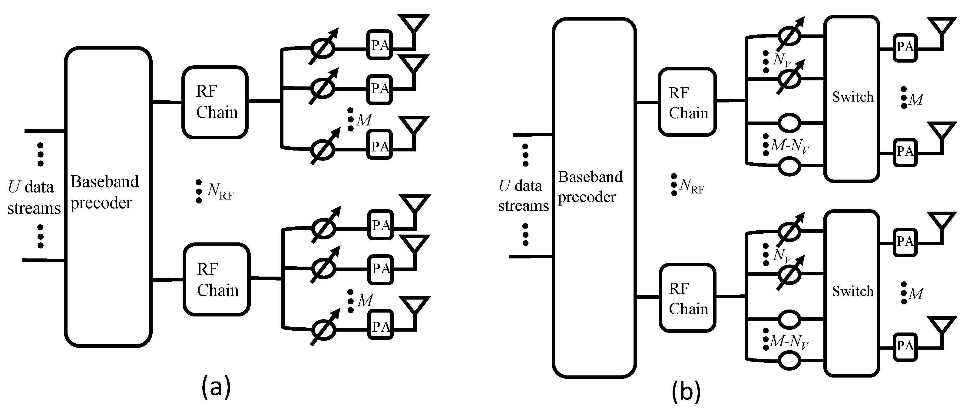
2.1. Partially Connected Hybrid Beamforming

Figure 1a shows the conventional PC-HBF architecture for downlink massive MIMO systems. The base station (BS) is equipped with N t transmit antennas and N R F RF chains. The BS simultaneously transmits U data streams to U mobile stations (MSs), where each mobile station has one antenna, and N R F = U is assumed. An RF chain is connected to a subarray, which contains M transmit antennas. The data streams are precoded using a digital precoder F B B C N R F × U at the baseband, followed by a VPS-based RF precoder F V C N t × N R F . Then, the signals are amplified using power amplifiers (PA) before they are transmitted via antennas. The signals received at U MSs can be stacked into y = [ y 1 , y 2 , , y U ] T , where y u is the received signal at user u, to yield y = H F V F B B s + n , where H = [ h 1 , , h U ] T is a composite downlink channel. Here, s C U × 1 is a vector of the transmitted symbols that satisfies E { s u s u * } = 1 and E { s u s j * } = 0 for i j , where s u is a symbol transmitted to user u. The noise vector n consists of independent and identically distributed noise signals [ n ] u CN ( 0 , σ 2 ) . The RF precoding matrix F V is a block diagonal matrix, where each block is an M-dimensional vector with unit modulus elements; M = N t / N R F . The phase of the nth VPS in the uth subarray can be set to the phase of the corresponding channel coefficient, that is, [ F V ] n , u = [ h u ] n for n { ( u 1 ) M + 1 , , u M } [17].

2.2. Channel Model

We adopted a geometric channel model, as in [17], for multi-user mmWave massive MIMO systems. In this model, each user is assumed to observe the same number of propagation paths, denoted by N p . The strength associated with the l th path observed by the u th user is represented by α l u CN ( 0 , 1 ) , and the random angle of departure (AoD), which is drawn independently from uniform distribution over [ 0 , 2 π ] , is denoted by ϕ l u . The channel of the u th user is given by h u H = N t N p l = 1 N p α l u a H ( ϕ l u ) , where a ( ϕ l u ) is the array response vector that depends only on the array structure. For a uniform linear array (ULA) antenna structure, the array response can be expressed as a U L A ( ϕ ) = 1 N t [ 1 , e j k d sin ( ϕ ) , , e j ( N t 1 ) k d sin ( ϕ ) ] T , where k = 2 π / λ , and d is the inter-element spacing [12].

3. VPS and CPS Based PC-HBF

3.1. Proposed Architecture

Figure 1b shows the proposed PC-HBF architecture. The signal model of this architecture is similar to that in Figure 1a, except for the analog precoding part. Specifically, in the proposed architecture, RF precoding based on VPSs and CPSs is employed, and hence in (2), F V is replaced with F V C C N t × N R F , which can be expressed as follows [13]:
F V C = f V C , 1 0 0 0 f V C , 2 0 0 0 0 0 f V C , U ,
where f V C , u = Δ U f u , u = 1 , , U , and f u = [ f V , u T , f C T ] T is a concatenated vector of f V , u and f C . Here, f V , u and f C represent the phases of N V VPSs and N C CPSs in the uth subarray, respectively. Notably, the phases of the CPSs are fixed to f C = [ 1 , e j 2 π N C , , e j 2 π ( N C 1 ) N C ] T for every subarray, where N C = M N V . Furthermore, Δ u = [ Δ u 1 Δ u 2 ] is a binary switch matrix that determines the allocations of phase shifters to transmit antennas for the uth subarray, where Δ u 1 B M × N V and Δ u 2 B M × N C denote the VPS-to-antenna and CPS-to-antenna allocations, respectively. Each VPS and CPS is allocated to a single antenna. Therefore, only a single element in every row and column of Δ u is one, whereas all other elements are zero.

3.2. Allocation of VPSs and CPSs to Antennas

In the present work, our aim is to design analog precoders by dynamically allocating VPSs and CPSs to transmit antennas for maximizing the system sum rate. The optimization can be formulated as follows:
max F V C , F B B u = 1 U log 2 1 + | h u H F V C f B B , u | 2 l u U | h u H F V C f B B , l | 2 + σ 2 , s . t . F V C F , Tr { F V C F B B F B B H F V C H } P ,
where P is the total transmit power at the base station, f B B , u = F B B ( : , u ) is the baseband precoding vector for s u , and F is the set of feasible RF precoding matrices of the proposed PC-HBF architecture that employs VPSs and CPSs simultaneously.
Finding an optimal solution to (2) can be immensely complicated. Therefore, we split optimization of the precoders into two stages. In the first stage, we set the digital precoder to an identity matrix and optimize the analog precoder by finding the switch matrix { Δ ^ u } that optimally allocates VPSs and CPSs to antennas. The corresponding optimization problem can be formulated as
{ Δ ^ u } u = 1 U = arg max { Δ u } u = 1 U u = 1 U log 2 1 + | h u , u H f V C , u | 2 l u U | h u , l H f V C , l | 2 + σ 2 s . t . m = 1 M [ Δ u ] m , j = 1 , m = 1 M [ Δ u ] i , m = 1 , i , j [ 1 , M ] ,
where h u , l is a sub-channel vector corresponding to the l th subarray, which is obtained by taking the elements in the range { ( l 1 ) M + 1 , l M } of h u . The VPS elements, [ f u ] m , m = 1 , , N V can be selected such that [ f u ] m = [ h u , u H Δ u ] m [17], which implies that f u is determined by the choice of Δ u . The two constraints in (3) reflect the allowed design of the switch matrix. In particular, the first constraint ensures that each antenna is connected to only a single phase shifter, whereas the second constraint ensures that each phase shifter is connected to only a single antenna.
After finding the optimal switch matrix Δ ^ u for each user, which provides F ^ V C , the corresponding solution of F V C , the unnormalized minimum mean square error (MMSE) precoder [18], is determined for digital precoding:
V ^ B B = ( F ^ V C H H ¯ H H ¯ F ^ V C + ρ F ^ V C H F ^ V C ) 1 · F ^ V C H H ¯ H ,
where H ¯ = γ H and ρ = U σ 2 P , whereas γ is the power-scaling factor such that the second constraint in (2) is satisfied. Then, the digital precoder is given by F ^ B B = 1 γ V ^ B B .
The problem in (3) is a combinatorial optimization problem, and to find its optimal solution, an exhaustive search through all possible combinations is required. The total number of candidates then becomes ( M ! / N V ! ) N R F , which can be an extremely large number in the case of massive MIMO systems. To resolve this problem, we have developed a low-complexity yet near-optimal solution.
The greedy VPS/CPS allocation algorithm, which is summarized in Algorithm 1, has been designed to reduce computational complexity while achieving near-optimal performance. In this algorithm, we initially consider a VPS-only PC-HBF, which comprises M × U VPSs and no CPSs. In each iteration, a VPS is replaced by a CPS in a greedy manner.
Specifically, in step 1 of Algorithm 1, F ^ V C is initially set to F ^ V , which can be obtained based on the phase of channel coefficients, as described in Section 2.1. In step 1, A represents the index set of the phase shifters that have been converted from VPS to CPS. In an iteration, among the unassigned CPSs in the uth subarray, whose indices are stored in L u , the CPS with the smallest phase difference relative to the mth VPS replaces the mth VPS to generate a new RF precoder F ˜ V C , as described in steps 7 and 8. Then, in step 9, we compute the corresponding sum-rate C m , u by using the capacity formula in (3). In step 10, the index of the selected CPS is stored as D m , u . We repeat this operation for all the remaining VPSs across subarrays. After searching all the remaining VPSs, in step 15, the best VPS-to-CPS conversion that yields the maximum sum rate is selected. In steps 16–18, the best RF precoder F ^ V C , set of unassigned CPSs L u , and set of selected VPSs A are updated. Finally, by using the RF precoder F ^ V C , the digital precoder V ^ B B is computed, which is subsequently normalized by the power-scaling factor γ in step 22.
Algorithm 1 Greedy allocation of VPSs and CPSs.
INPUT: H , F V , f C .
OUTPUT: F ^ V C , F B B .
1:
Initialize F ^ V C = F V , L 1 = L 2 = = L u = { 1 , , N C } , A = an empty set .
2:
forj = 1 to N C × U do
3:
  for u = 1 to U do
4:
    for m = 1 to M do
5:
      if ( m , u ) A then
6:
         F V C = F ^ V C
7:
           l 🟉 = arg min l L u { [ h u , u ] m [ f C ] l }
8:
           [ f V C , u ] m = [ f C ] l 🟉
9:
          Compute C m , u based on (3).
10:
         D m , u = l 🟉
11:
        end if
12:
      end for
13:
    end for
14:
   ( m 🟉 , u 🟉 ) = arg max ( m , u ) A C m , u
15:
   l 🟉 = D m 🟉 , u 🟉
16:
  Update [ f ^ V C , u ] m = [ f C ] l 🟉 .
17:
   Remove l 🟉 from L u .
18:
  Add ( m 🟉 , u 🟉 ) to A .
19:
end for
20:
Compute V ^ B B based on (4).
21:
Compute γ = T r { F ^ V C V ^ B B V ^ B B H F ^ V C H } P .
22:
F ^ B B 1 γ V ^ B B .

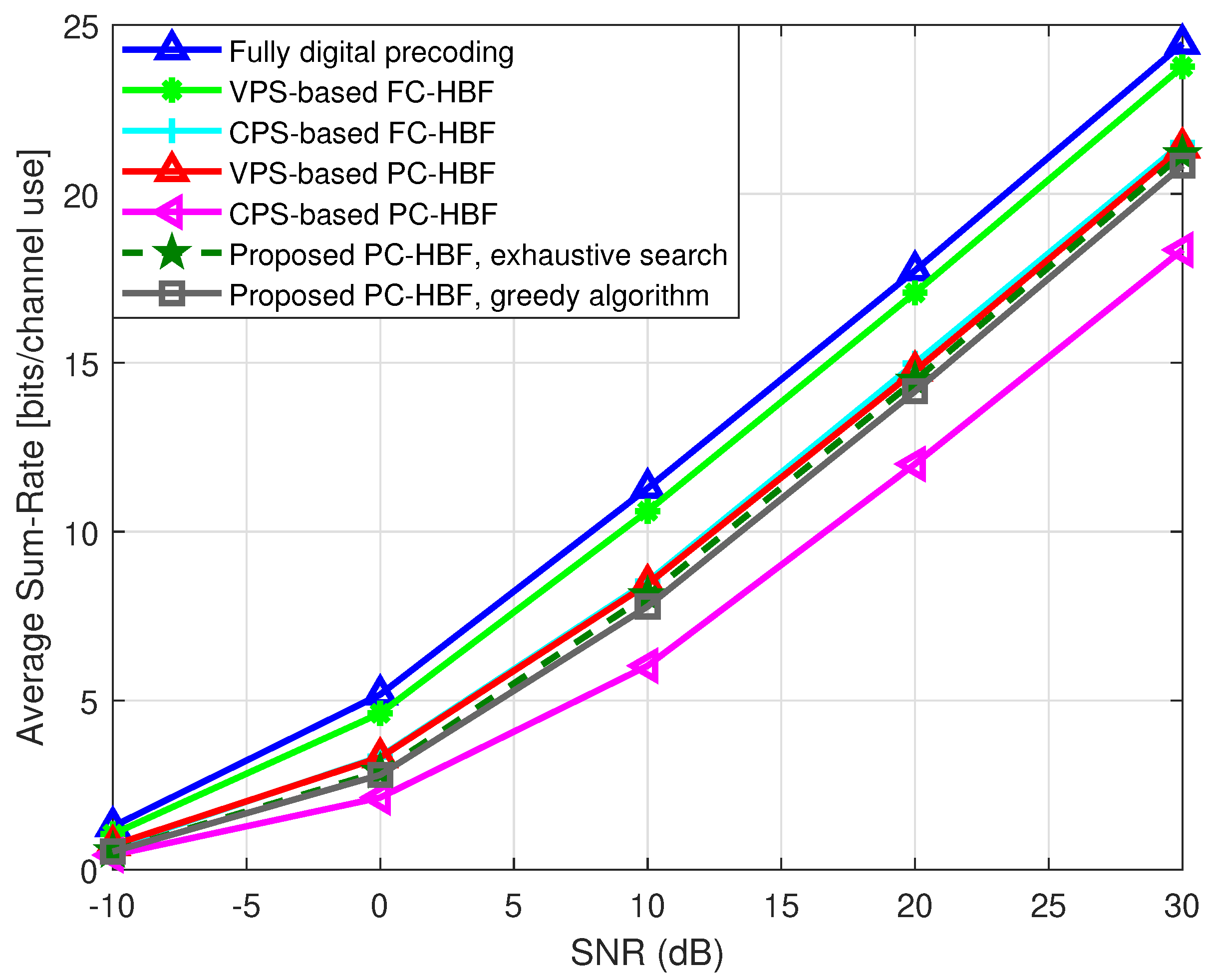
4. Simulation Results

In this section, we present the simulation results to evaluate the performance of the proposed architecture. For comparison, we consider the MMSE precoding scheme for fully digital MIMO precoding, conjugate precoding scheme for VPS-based HBF [17], and scheme for CPS-based HBF [19]. For the CPS-based HBF scheme, we assume that each CPS is connected only to a single antenna for even distribution of signal power across transmit antennas. For a BS, we consider a ULA antenna array [17] with antenna spacing d = λ / 2 . The number of scattering paths is set to N p = 10 . The signal-to-noise ratio (SNR) in all simulation results is defined as SNR = P / U σ 2 .
First, we analyze the optimality of the proposed greedy algorithm. In massive MIMO systems, which comprise a large number of antennas, the total number of candidates to be examined in exhaustive search is massive, which makes it almost impossible to test its performance. Therefore, we compare the performances of the exhaustive search and the proposed greedy algorithm by applying them to a relatively small system. Figure 2 shows the sum-rate performances of various schemes, including the proposed architecture with exhaustive search for N t = 12 , U = 2 , and M = 6 . Moreover, we assume two VPSs and four CPSs for each subarray in the proposed architecture. The simulation results in Figure 2 show that when the exhaustive search algorithm is employed for VPS/CPS allocation, the performance of the proposed architecture is close to that of the VPS-based PC-HBF scheme over the entire SNR range. Moreover, Figure 2 shows that the performance of the proposed greedy algorithm is only marginally lower than that of the exhaustive search algorithm. Furthermore, at SNR = 20 dB , the sum rate achieved by the proposed architecture is 22 % higher than that of the CPS-based PC-HBF scheme.
Figure 3 shows the simulation results obtained for a system with 64 antennas, which serves four users. We assume the number of VPSs as 2, 4, and 8, and the number of CPSs as 15, 12, and 8 in each subarray of the proposed architecture. In Figure 3, the performance of the proposed PC-HBF architecture with the greedy algorithm is close to that of the VPS-based PC-HBF system over the entire SNR range. For example, the performance loss of the proposed architecture is only 4.1% and 1.1% at SNR = 20 dB, respectively, when N V is 2 and 8. In this environment, the proposed PC-HBF architecture with the exhaustive algorithm is not tested, but the sum-rate of greedy algorithm is close to that of the VPS-based PC-HBF architecture, which implies that the greedy algorithm provides a near-optimal solution to the VPS/CPS allocation problem in the proposed PC-HBF architecture. Similar to Figure 2, the FC-HBF scheme outperforms the PC-HBF scheme. However, the former scheme requires a significantly greater number of phase shifters, which can result in higher energy consumption and lower energy efficiency compared to those of the PC-HBF scheme, as evidenced by the following simulation results.
Moreover, we evaluate the energy efficiency (EE) of the proposed architecture, which is defined as
EE = Spectral efficiency Total power consumption [ bps / Hz / W ] .
In other words, EE indicates the number of bits that can be reliably transmitted per unit of energy [14]. Figure 4 shows compares the energy efficiency for various numbers of antennas and users. For this comparison, we employ the energy consumption model conventional given in [8]. In Figure 4, the proposed architecture outperforms the conventional schemes in terms of energy efficiency. In particular, the energy efficiency of the proposed HBF scheme is 19.0 % , 21.6 % , and 27.3 % higher than those of the CPS-based PC-HBF, VPS-based PC-HBF, and CPS-based FC-HBF schemes, respectively, when N t = 128 and U = 8 are assumed.
Finally, we compare the computational complexity of the proposed greedy algorithm with that of exhaustive search for various numbers of antennas when a BS serves two users and each subarray in the proposed architecture contains two VPSs. We define computational complexity as the total number of addition and multiplication operations. Table 1 presents the simulation results of computational complexity obtained by varying the number of antennas from 16 to 64 and setting the number of users to two. The results show that the proposed greedy VPS/CPS allocation algorithm is significantly less complexity than the exhaustive search algorithm while achieving nearly the same sum-rate. In the proposed greedy algorithm, complexity depends mainly on the the number of iterations and the computation of (3) in step 9. The total number of iterations is N C × U × U × M , which can be written as N C U N t because we have U × M = N t . The computational complexity of (3) is proportional to U N t , and it is computed throughout the iterations. We note that the other steps in the algorithm have lower complexity orders compared to step 9. Therefore, the overall complexity of the proposed algorithm can be expressed as O ( N C U 2 N t 2 ) . Furthermore, if we assume that N V is fixed to a constant value, as in Table 1, the overall complexity of the proposed algorithm can be rewritten as O ( U N t 3 ) . For a fixed value of U, its complexity becomes approximately proportional to N t 3 , as presented in Table 1.

5. Conclusions

We have presented a novel PC-HBF architecture for massive MIMO systems that employs both VPSs and CPSs for analog precoding. To maximize the sum rate of this architecture, it is necessary to find the optimal allocation of VPSs and CPSs to transmit antennas, and we formulate the corresponding optimization as a combinatorial problem. However, the use of exhaustive search to find the optimal solution to this problem involves excessively large complexity for massive MIMO systems. Hence, we develop a greedy VPS/CPS allocation algorithm that provides a near-optimal solution. The simulation results show that the performance of the proposed HBF architecture is close to that of VPS-based PC-HBF scheme, but it requires substantially fewer VPSs in each subarray, which reduces energy consumption. In the simulation results, the energy efficiency of the proposed architecture is 19.0–27.3% higher than those of conventional architectures for N t = 128 and U = 8 .

Author Contributions

Data curation, G.M.G.; Methodology, G.M.G. and K.L.; Supervision, K.L.; Writing—original draft, G.M.G.; Writing—review & editing, G.M.G. and K.L.

Funding

This research was supported in part by Basic Science Research Program through the National Research Foundation of Korea (NRF) funded by the Ministry of Education(NRF-2019R1A6A1A03032119). This research was also supported in part by Basic Science Research Program through the NRF funded by the Ministry of Education (NRF-2016R1D1A1B03933122).

Conflicts of Interest

The authors declare no conflict of interest.

References

  1. Akpakwu, G.A.; Silva, B.J.; Hancke, G.P.; Abu-Mahfouz, A.M. A survey on 5G networks for the internet of things: Communication technologies and challenges. IEEE Access 2017, 6, 3619–3647. [Google Scholar] [CrossRef]
  2. Castanheira, D.; Lopes, P.; Silva, A.; Gameiro, A. Hybrid beamforming designs for massive MIMO millimeter-wave heterogeneous systems. IEEE Access 2017, 5, 21806–21817. [Google Scholar] [CrossRef]
  3. Hefnawi, M. Hybrid beamforming for millimeter-wave heterogeneous networks. Electronics 2019, 8, 133. [Google Scholar] [CrossRef]
  4. Sun, S.R.; Rappaport, T.S.; Shaft, M. Hybrid beamforming for 5G millimeter-wave multi-cell networks. IEEE Infcomw. 2018, 4, 589–596. [Google Scholar]
  5. Sanguinetti, L.; Moustakas, A.L.; Bjornson, E.; Debbah, M. Large system analysis of the energy consumption distribution in multi-user MIMO systems with mobility. IEEE Trans. Wirel. Commun. 2015, 14, 1730–1745. [Google Scholar] [CrossRef]
  6. Vook, F.W.; Ghosh, A.; Thomas, T.A. MIMO and beamforming solutions for 5G technology. In Proceedings of the 2014 IEEE MTT-S International Microwave Symposium (IMS2014), Tampa, FL, USA, 1–6 June 2014; pp. 142–149. [Google Scholar]
  7. Vizziello, A.; Savazzi, P.; Kauchik, R.C. A kalman based hybrid precoding for multi-User millimeter wave MIMO systems. IEEE Access 2018, 6, 2169–3536. [Google Scholar] [CrossRef]
  8. Mendez-Rial, R.; Rusu, C.; Gonzalez-Prelcic, N.; Alkhateeb, A.; Heath, R.W. Hybrid MIMO architectures for millimeter wave communications: Phase shifters or switches? IEEE Access 2016, 4, 247–267. [Google Scholar] [CrossRef]
  9. Sohrabi, F.; Yu, W. Hybrid digital and analog beamforming design for large-scale antenna arrays. IEEE J. Sel. Top. Signal Process 2016, 10, 501–513. [Google Scholar] [CrossRef]
  10. Payami, S.; Ghoraishi, M.; Dianati, M. Hybrid beamforming for large antenna arrays with phase shifter selection. IEEE Trans. Wirel. Commun. 2016, 15, 7258–7271. [Google Scholar] [CrossRef]
  11. Alkhateeb, A.; El Ayach, O.; Leus, G.; Heath, R.W. Channel estimation and hybrid precoding for millimeter wave cellular systems. IEEE J. Sel. Top. Signal Process 2014, 8, 831–846. [Google Scholar] [CrossRef]
  12. Ayach, O.E.; Rajagopal, S.; Abu-Surra, S.; Pi, Z.; Heath, R.W. Spatially sparse precoding in millimeter wave MIMO systems. IEEE Trans. Wirel. Commun. 2014, 13, 1499–1513. [Google Scholar] [CrossRef]
  13. Yu, X.; Shen, J.C.; Zhang, J.; Letaief, K.B. Alternating minimization algorithms for hybrid precoding in millimeter wave MIMO systems. IEEE J. Sel. Top. Signal Process 2016, 10, 485–500. [Google Scholar] [CrossRef]
  14. Gao, X.; Dai, L.; Han, S.; Chih-Lin, I.; Heath, R.W. Energy-efficient hybrid analog and digital precoding for mmWave MIMO systems with large antenna arrays. IEEE J. Sel. Area Commun. 2016, 34, 998–1009. [Google Scholar] [CrossRef]
  15. Payami, S.; Ghoraishi, M.; Dianati, M. Hybrid beamforming with reduced number of phase shifters for massive MIMO systems. IEEE Trans. Veh. Technol. 2018, 67, 4843–4851. [Google Scholar] [CrossRef]
  16. Li, M.; Wang, Z.; Li, H.; Liu, Q.; Zhou, L. A hardware-efficient hybrid beamforming solution for mmWave MIMO systems. IEEE Wirel. Commun. 2019, 26, 137–143. [Google Scholar] [CrossRef]
  17. Liang, L.; Xu, W.; Dong, X. Low-complexity hybrid precoding in massive multiuser MIMO systems. IEEE Wirel. Commun. Lett. 2014, 3, 653–656. [Google Scholar] [CrossRef]
  18. Nguyen, D.H.N.; Le, L.B.; Le-Ngoc, T.; Heath, R.W. Hybrid MMSE precoding and combining designs for mmWave multiuser systems. IEEE Access 2017, 5, 19167–19181. [Google Scholar] [CrossRef]
  19. Alkhateeb, A.; Nam, Y.H.; Zhang, J.C.; Heath, R.W. Massive MIMO combining with switches. IEEE Wirel. Commun. Lett. 2016, 5, 232–235. [Google Scholar] [CrossRef]
Figure 1. Hybrid precoding for massive multiple-input multiple output (MIMO) systems: (a) conventional (PC-HBF architecture; (b) proposed partially connected hybrid beamforming (PC-HBF) architecture.
Applsci 09 04476 g001
Figure 2. Average sum rate versus SNR. N t = 12 and U = 2 .
Applsci 09 04476 g002
Figure 3. Average sum rate versus SNR. N t = 64 and U = 4 .
Applsci 09 04476 g003
Figure 4. Energy efficiency comparison against number of users ( U = N R F ). N t = (64, 128, 256) and SNR = 20 dB.
Applsci 09 04476 g004
Table 1. Complexity analysis.
Number of AntennasProposed PC-HBF, Exhaustive SearchProposed PC-HBF, Greedy Algorithm
16 6.2 × 10 11 5.6 × 10 4
32 8.4 × 10 28 4.1 × 10 5
48 1.2 × 10 49 1.4 × 10 6
64 1.8 × 10 71 3.2 × 10 6

