Large-Scale Pumped Thermal Electricity Storages—Converting Energy Using Shallow Lined Rock Caverns, Carbon Dioxide and Underground Pumped-Hydro


Abstract
Featured Application
Abstract
1. Introduction
2. Methods
3. Results of Literature Review and Economic Assessment
3.1. Novel Use of Existing LRC Cavern for UPHES
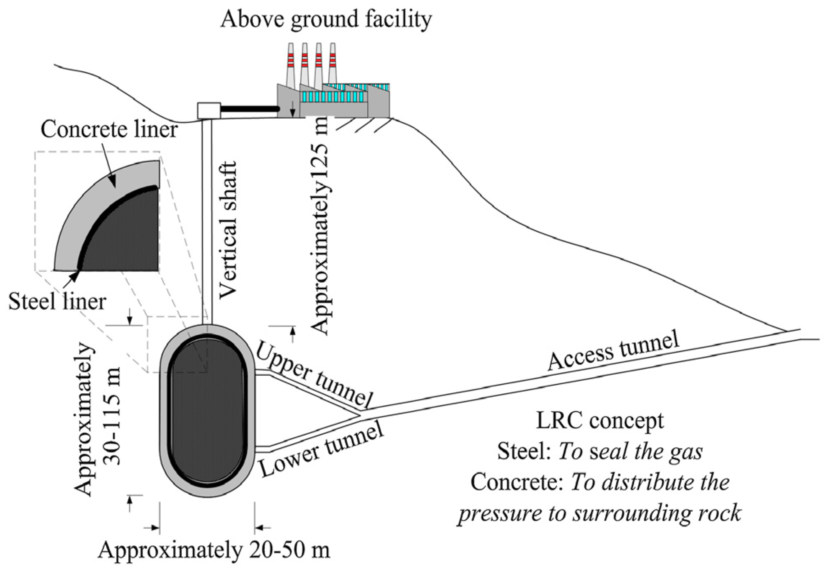
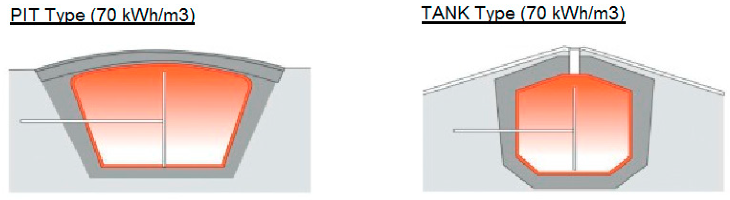
3.1.1. History and Characteristics of LRC Caverns
3.1.2. Use of LRC Cavern for Hydro-Pneumatic UPHES
3.2. Replacing Air by CO2 at Liquid-Vapor Equilibrium in a Hydro-Pneumatic UPHES
3.2.1. Reaching Constant Pressure for a Hydro-Pneumatic UPHES
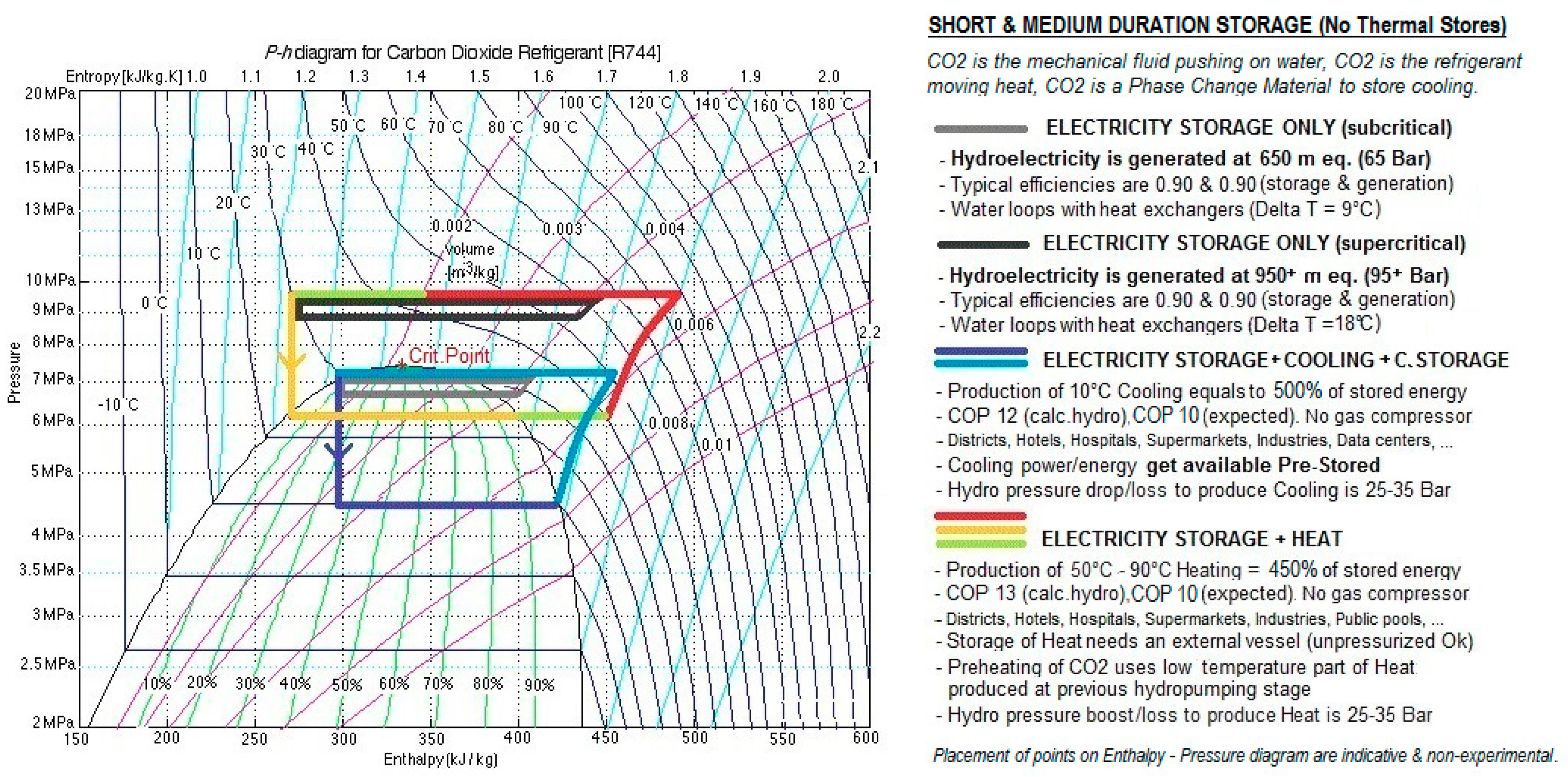
3.2.2. Operation as a Storage of Short or Medium Duration
3.2.3. Operation as Short-Duration or Medium-Duration Storage, plus as Heat-Pump
3.2.4. Economic Evaluation as a Storage of Short and Medium Duration, with or without the Heat-Pump Function. Comparison with Electrochemical Storage
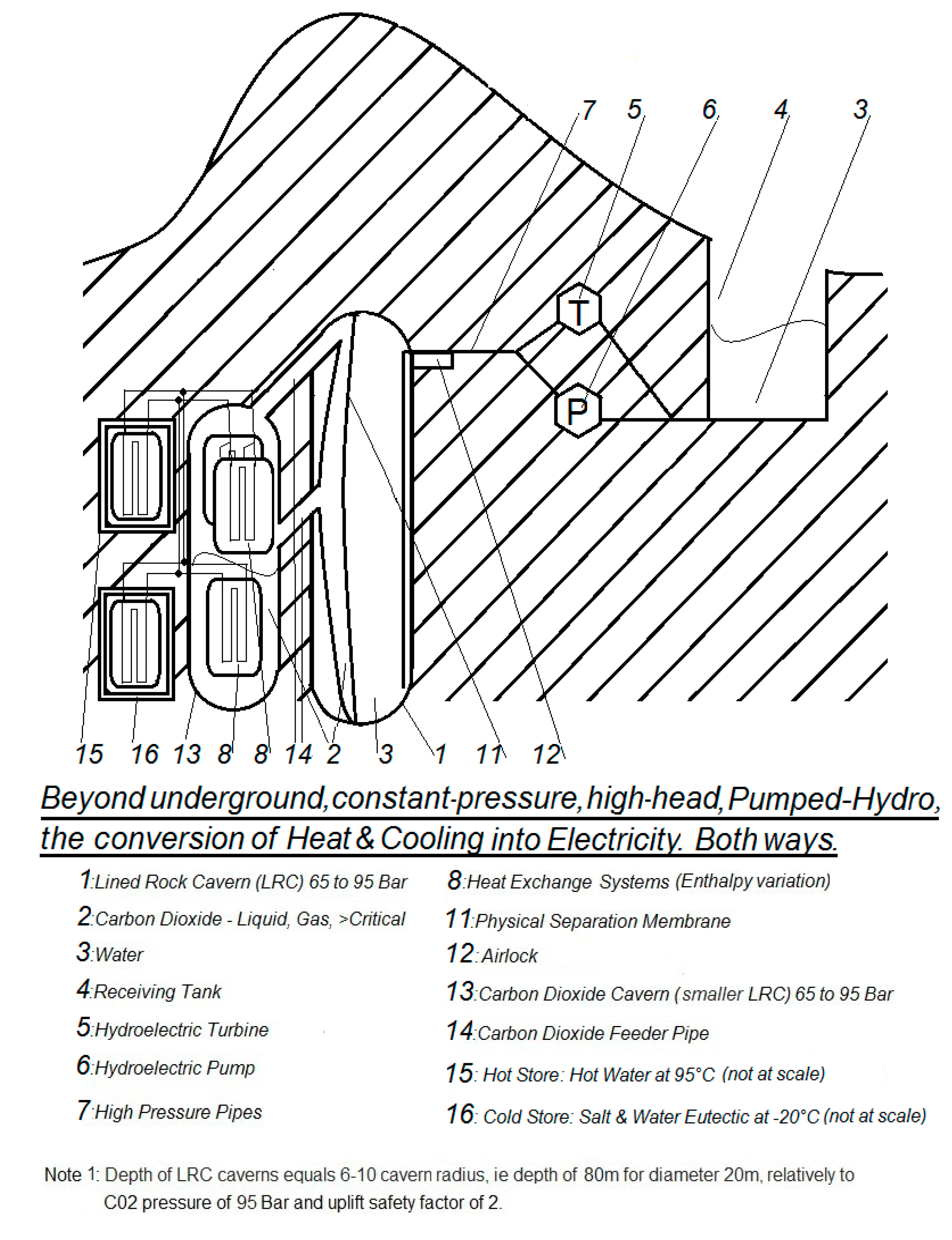
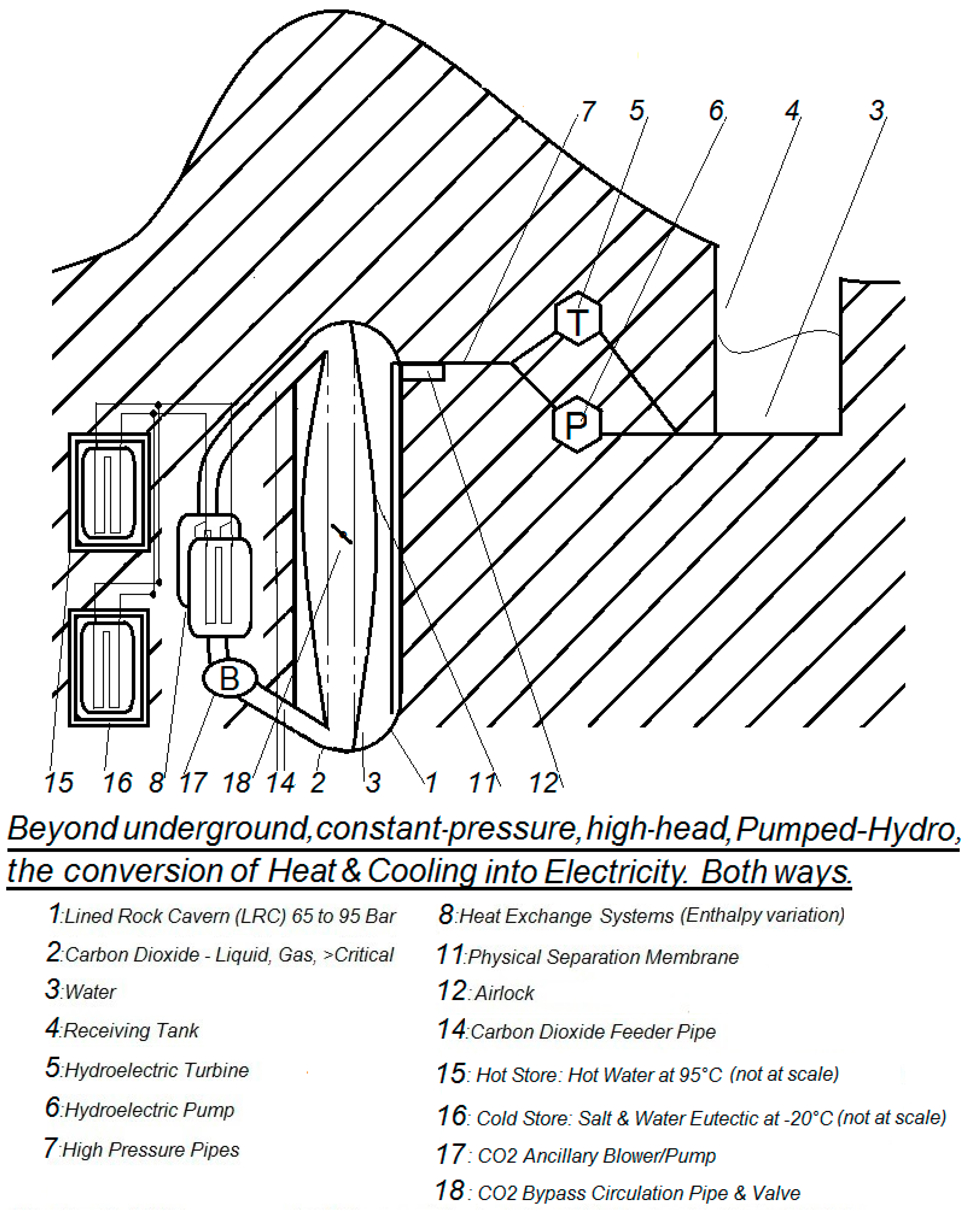
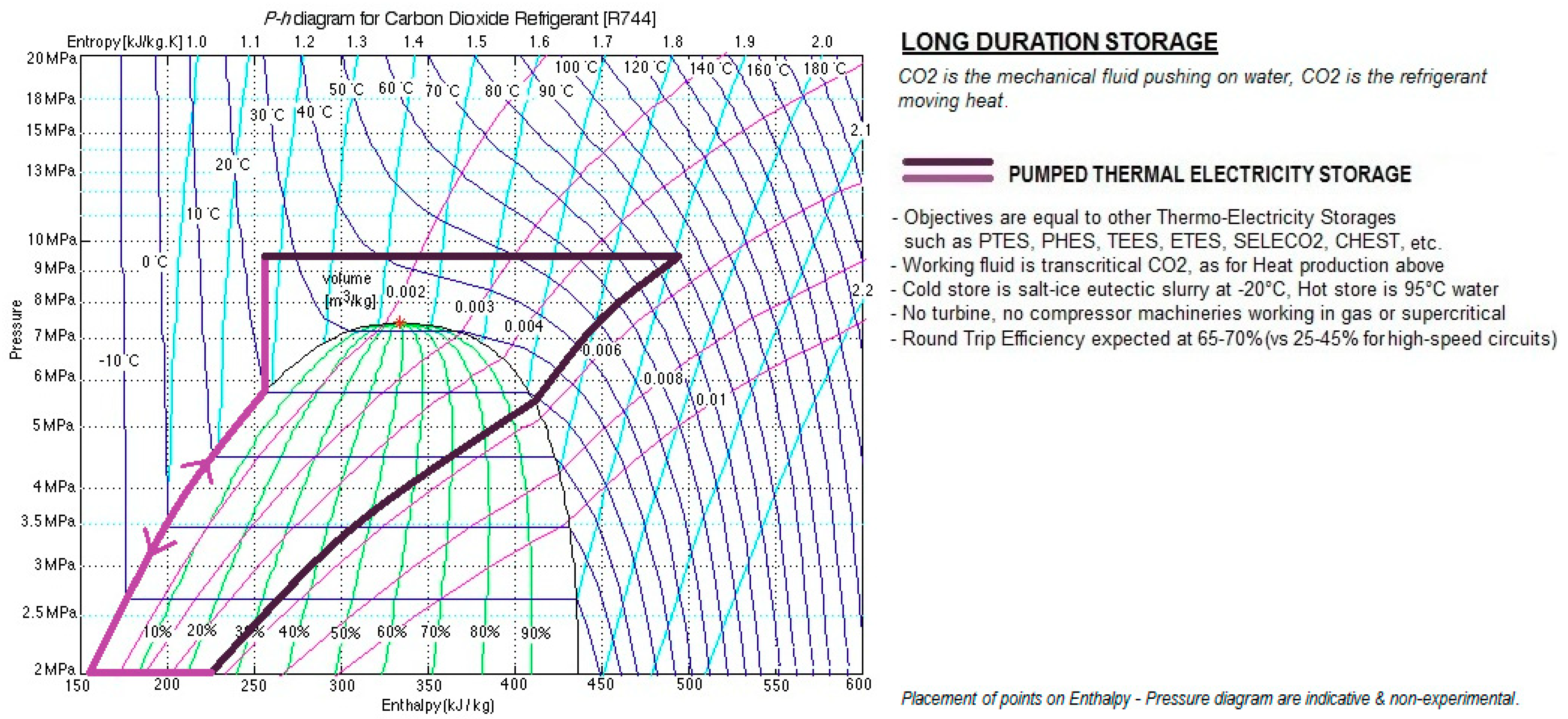
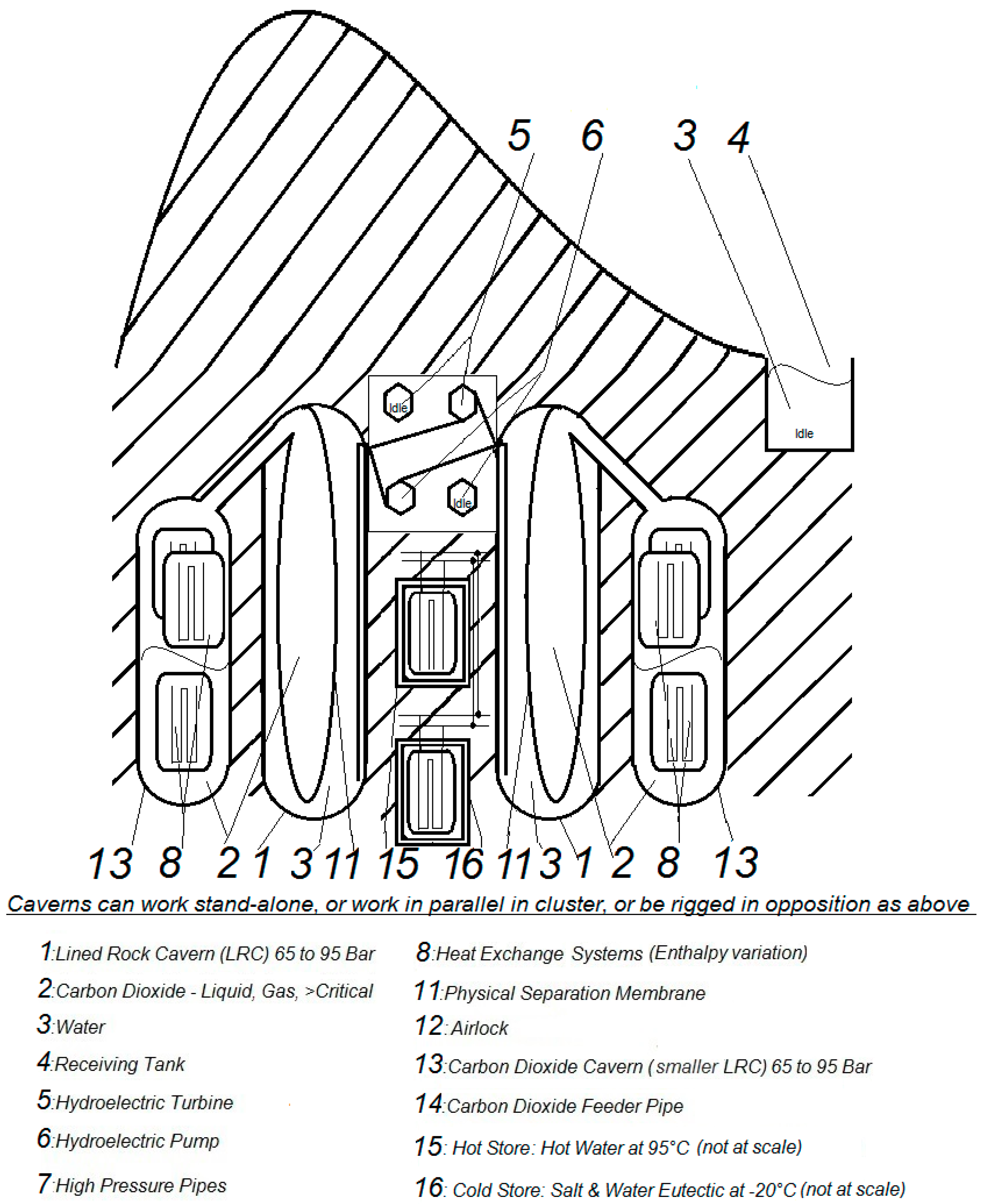
3.3. A Novel Long-Duration Storage, Hybrid of Hydro-Pneumatic UPHES with PTES
3.3.1. Overall Considerations for Long Duration Storage
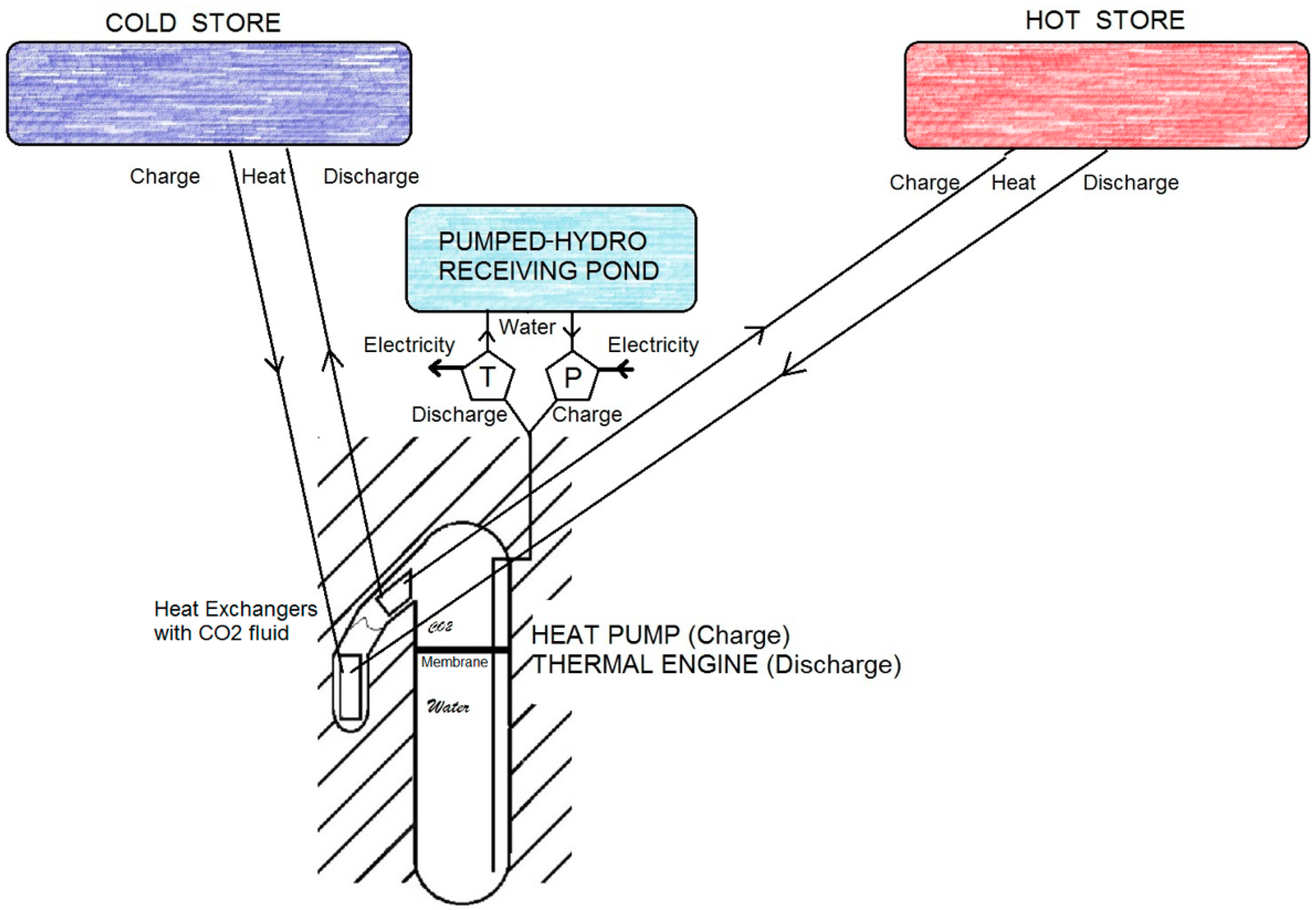
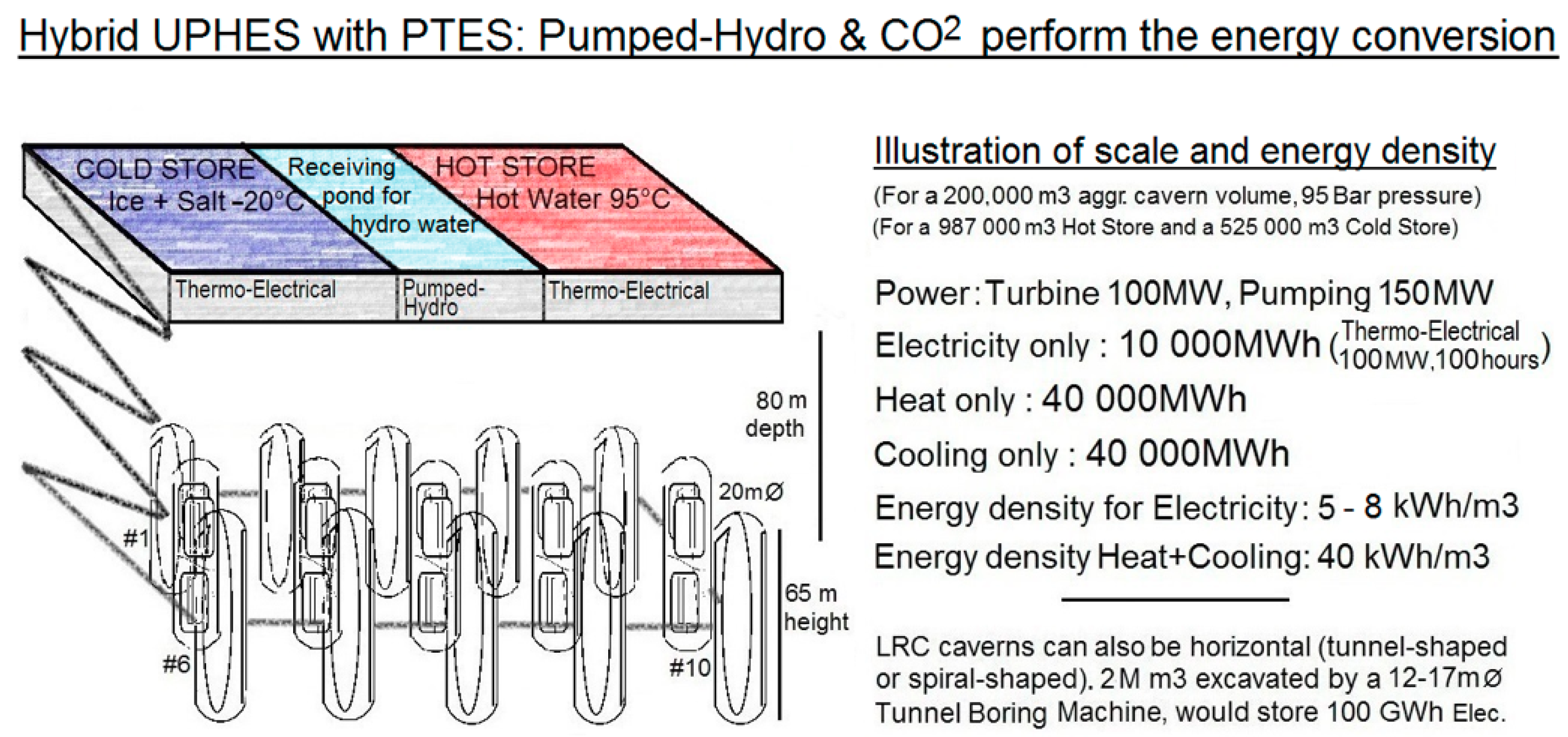
3.3.2. Moving the Storage Capacity outside of UPHES, toward Thermal Stores
3.3.3. Economic Targets of the UPHES-PTES Hybrid Long-Duration Storage
4. Discussion
5. Conclusions
6. Patents
Author Contributions
Funding
Conflicts of Interest
References
- Ram, M.; Bogdanov, D.; Aghahosseini, A.; Gulagi, A.; Oyewo, A.S.; Child, M.; Caldera, U.; Sadovskaia, K.; Farfan, J.; Barbosa, L.S.N.S.; et al. Global Energy System based on 100% Renewable Energy—Energy Transition in Europe Across Power, Heat, Transport and Desalination Sectors; Study by LUT University and Energy Watch Group; Research Reports 89; Lappeenranta University of Technology: Lappeenranta, Finland, December 2018; ISBN 978-952-335-329-9. ISSN 2243-3376. [Google Scholar]
- International Energy Agency. The Future of Cooling; OECD: Paris, France, 2018. [Google Scholar]
- Cavazzini, G. Solutions for Pumped Hydro Energy Storage Plants. Sci. Trends 2018. [Google Scholar] [CrossRef]
- Tallini, A.; Vallati, A.; Cedola, L. Applications of micro-CAES systems: Energy and economic Analysis. Energy Procedia 2015, 82, 797–804. [Google Scholar] [CrossRef]
- Mercangöz, M.; Hemrle, J.; Kaufmann, L.; Z’Graggen, A.; Ohler, C. Electrothermal energy storage with transcritical CO2 cycles. Energy 2012, 45, 407–415. [Google Scholar] [CrossRef]
- McTigue, J.D.; White, A.J.; Markides, C.N. Parametric studies and optimisation of pumped thermal electricity storage. Appl. Energy 2015, 137, 800–811. [Google Scholar] [CrossRef]
- Georgiou, S.; Shah, N.; Markides, C.N. A thermo-economic analysis and comparison of pumped-thermal and liquid-air electricity storage systems. Appl. Energy. 2018, 226, 1119–1133. [Google Scholar] [CrossRef]
- Dietrich, A.; Dammel, F.; Stephan, P. Exergoeconomic Analysis of a Pumped Heat Electricity Storage System with Concrete Thermal Energy Storage. Int. J. Thermodyn. 2016, 19, 43–51. [Google Scholar] [CrossRef][Green Version]
- Deepsource. Siemens-Gamesa Electric Thermal Energy Storage. Available online: https://deepresource.wordpress.com/2019/06/17/siemens-gamesa-electric-thermal-energy-storage/ (accessed on 30 September 2019).
- Pujades, E.; Willems, T.; Bodeux, S.; Orban, P.; Dassargues, A. Underground pumped storage hydroelectricity using abandoned works (deep mines or open pits) and the impact on groundwater flow. Hydrogeol. Geol. 2016, 24, 1531–1546. [Google Scholar] [CrossRef]
- SHELL Internationale Research Maatschappij B.V of Netherlands. Storage and Recovery. Patent No. 0196 690, 18 October 1989. [Google Scholar]
- Bi, J.; Jiang, T.; Chen, W.; Ma, X. Research on Storage Capacity of Compressed Air Pumped Hydro Energy Storage Equipment; North China Electric Power University, Beijing, China. Energy Power Eng. 2013, 5, 26–30. [Google Scholar] [CrossRef]
- Odukomaiya, A.; Abu-Heiba, A.; Gluesenkamp, K.R.; Abdelaziz, O.; Jackson, R.K.; Daniel, C.; Graham, S.; Momen, A.M. Thermal analysis of near-isothermal compressed gas energy storage system. Appl. Energy 2016, 179, 948–960. [Google Scholar] [CrossRef]
- Johansson, J. Storage of highly compressed gases in underground Lined Rock Caverns—More than 10 years of experience. In Proceedings of the World Tunnel Congress 2014–Tunnels for a Better Life, Foz do Iguaçu, Brazil, 9–15 May 2014. [Google Scholar]
- Rutqvist, J.; Kim, H.M.; Ryu, D.W.; Synn, J.H.; Song, W.K. Modeling of coupled thermodynamic and geomechanical performance of underground compressed air energy storage in lined rock caverns. Int. J. Rock Mech. Min. Sci. 2012, 52, 71–81. [Google Scholar] [CrossRef]
- Kim, H.M.; Rutqvist, J.; Jeong, J.H.; Choi, B.H.; Ryu, D.W.; Song, W.K. Characterizing Excavation Damaged Zone and Stability of Pressurized Lined Rock Caverns for Underground Compressed Air Energy Storage; Lawrence Berkeley National Laboratory (LBNL): Berkeley, CA, USA, 2014. [Google Scholar] [CrossRef]
- Kim, H.M.; Park, D.; Ryu, D.W.; Song, W.K. Parametric sensitivity analysis of ground uplift above pressurized underground rock caverns. Eng. Geol. 2012, 135, 60–65. [Google Scholar] [CrossRef]
- Perazzelli, P.; Anagnostou, G. Design issues for compressed air energy storage in sealed underground cavities. J. Rock Mech. Geotech. Eng. 2016, 8, 314–328. [Google Scholar] [CrossRef]
- Tunsakul, J.; Jongpradist, P.; Kim, H.M.; Nanakorn, P. Evaluation of rock fracture patterns based on the element-free Galerkin method for stability assessment of a highly pressurized gas storage cavern. Acta Geotech. 2018, 13, 817–832. [Google Scholar] [CrossRef]
- Glamheden, R.; Curtis, P. Excavation of a cavern for high-pressure storage of natural gas. Tunn. Undergr. Space Technol. 2006, 21, 56–67. [Google Scholar] [CrossRef]
- Laine, H.S.; Salpakari, J.; Looney, E.E.; Savin, H.; Peters, I.M.; Buonassisi, T. Meeting global cooling demand withphotovoltaics during the 21st century. R. Soc. Chem. 2019. [Google Scholar] [CrossRef]
- Shwartz, M.; Stanford University. Stanford Scientists Calculate the Carbon Footprint of Grid-Scale Battery Technologies. Available online: https://news.stanford.edu/news/2013/march/store-electric-grid-030513.html (accessed on 30 September 2019).
- Energinet, Danish Energy Agency. Technology Data for Energy storage. First published: November 2018, latest update: February 2019. Available online: http://www.ens.dk (accessed on 30 September 2019).
- Kim, Y.M.; Shin, D.G.; Lee, S.Y.; Favrat, D. Isothermal transcritical CO2 cycles with TES (thermal energy storage) for electricity storage. Energy 2013, 49, 484–501. [Google Scholar] [CrossRef]


| Component of Energy Capacity | Volume in m3 | Cost in USD/m3 | Cost in USD |
|---|---|---|---|
| LRC cavern (400 MWh @ 1.750 kWh per m3) | 230,000 | 300 | 69,000,000 |
| Receiving pond for Hydro water | 230,000 | 30 | 6,900,000 |
| Total Capex | - | - | 75,900,000 |
| Total with 5% provision for CO2 cost, etc. | - | - | 80,000,000 |
| Total Capex per KWh of energy | - | - | 200 |
| Components of Energy Capacity | Volume in m3 | Cost in USD/m3 | Cost in USD |
|---|---|---|---|
| Hot Store for 10 GWh Electrical (atmosph.) | 987,000 | 40 | 39,480,000 |
| Cold Store for 10 GWh Electrical (atmosph.) | 525,000 | 100 | 52,500,000 |
| Total Capex | - | - | 91,980,000 |
| Total Capex with 9% ancillary provision | - | - | 100,000,000 |
| Total Capex per KWh of energy | - | - | 10 |
© 2019 by the authors. Licensee MDPI, Basel, Switzerland. This article is an open access article distributed under the terms and conditions of the Creative Commons Attribution (CC BY) license (http://creativecommons.org/licenses/by/4.0/).
Share and Cite
Lalanne, P.; Byrne, P. Large-Scale Pumped Thermal Electricity Storages—Converting Energy Using Shallow Lined Rock Caverns, Carbon Dioxide and Underground Pumped-Hydro. Appl. Sci. 2019, 9, 4150. https://doi.org/10.3390/app9194150
Lalanne P, Byrne P. Large-Scale Pumped Thermal Electricity Storages—Converting Energy Using Shallow Lined Rock Caverns, Carbon Dioxide and Underground Pumped-Hydro. Applied Sciences. 2019; 9(19):4150. https://doi.org/10.3390/app9194150
Chicago/Turabian StyleLalanne, Pascal, and Paul Byrne. 2019. "Large-Scale Pumped Thermal Electricity Storages—Converting Energy Using Shallow Lined Rock Caverns, Carbon Dioxide and Underground Pumped-Hydro" Applied Sciences 9, no. 19: 4150. https://doi.org/10.3390/app9194150
APA StyleLalanne, P., & Byrne, P. (2019). Large-Scale Pumped Thermal Electricity Storages—Converting Energy Using Shallow Lined Rock Caverns, Carbon Dioxide and Underground Pumped-Hydro. Applied Sciences, 9(19), 4150. https://doi.org/10.3390/app9194150