Effects of Surface Roughness and Force of Electrode on Resistance Spot Weldability of Aluminum 6061 Alloy


Abstract
1. Introduction
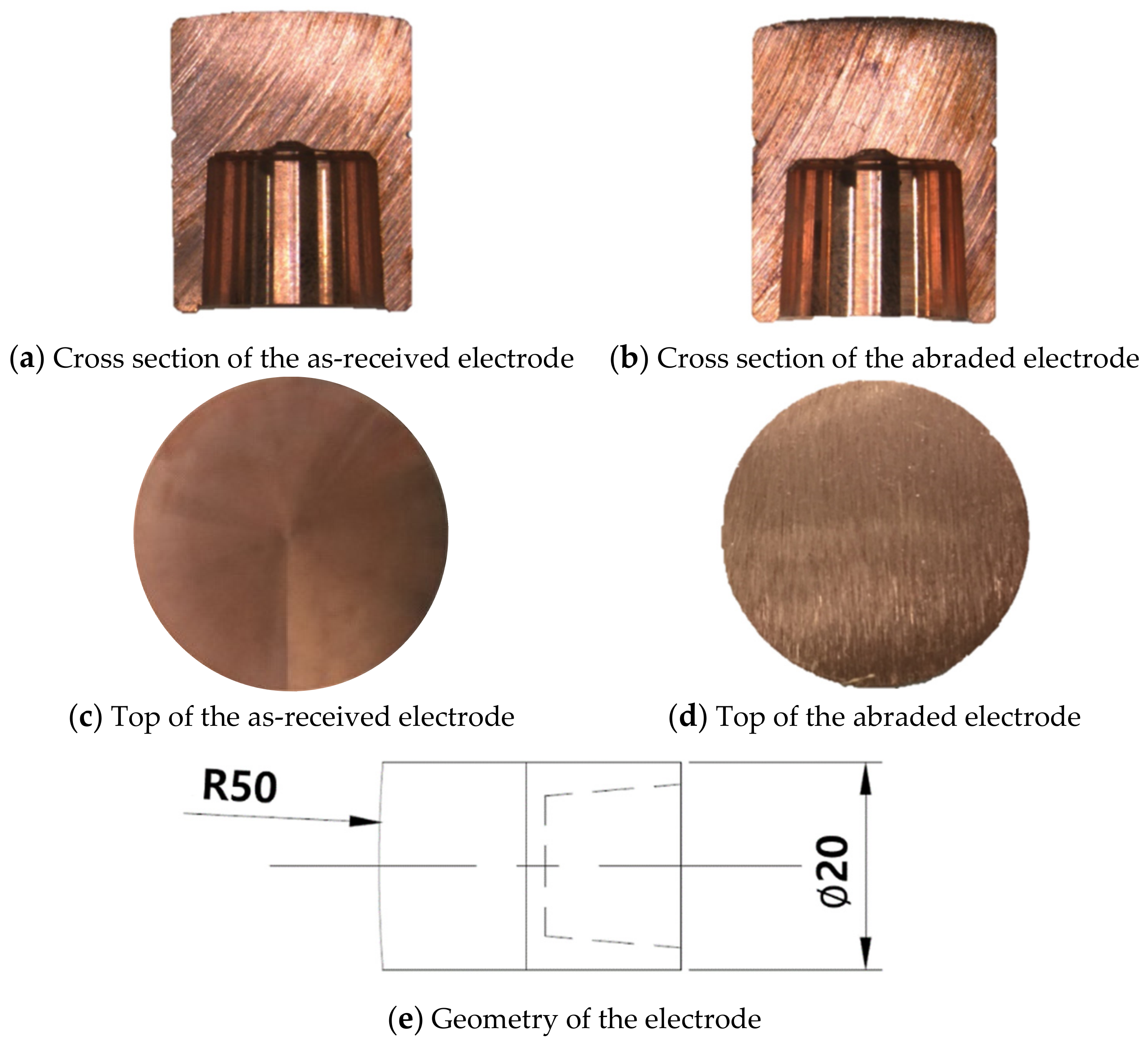
2. Materials and Methods
3. Results and Discussion
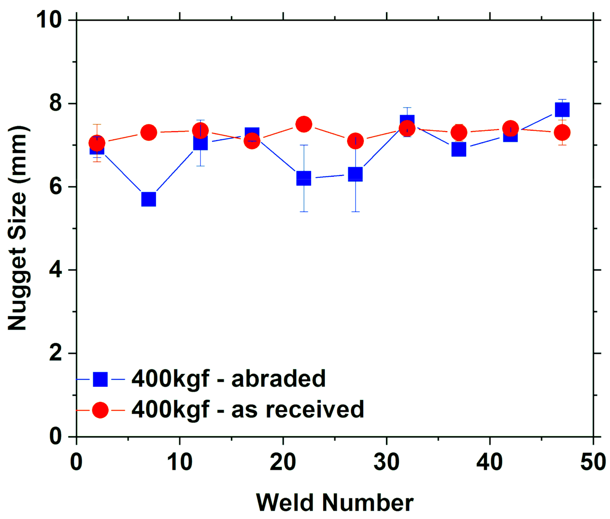
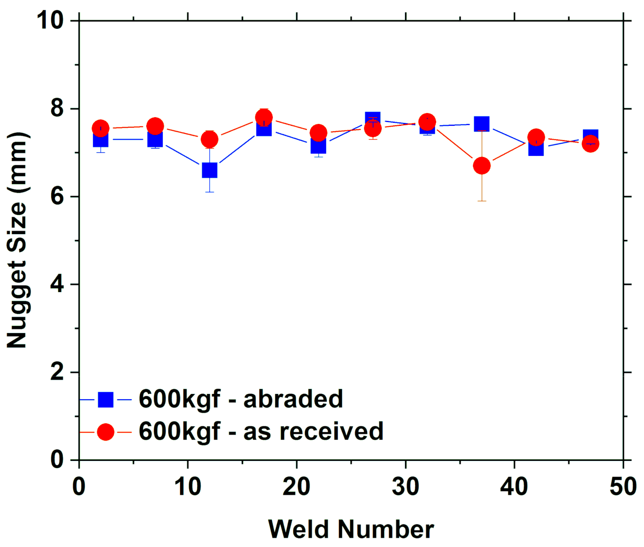
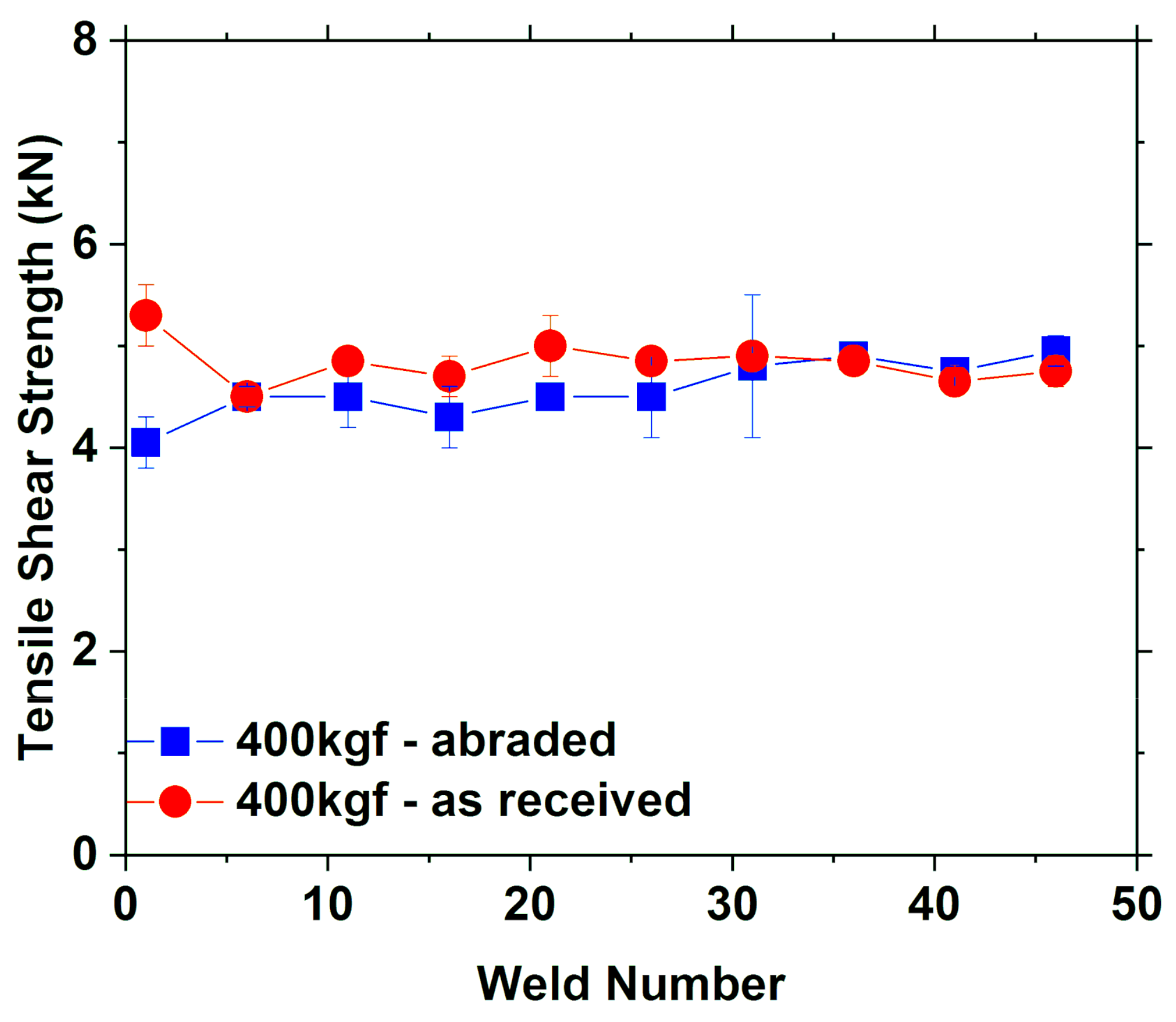
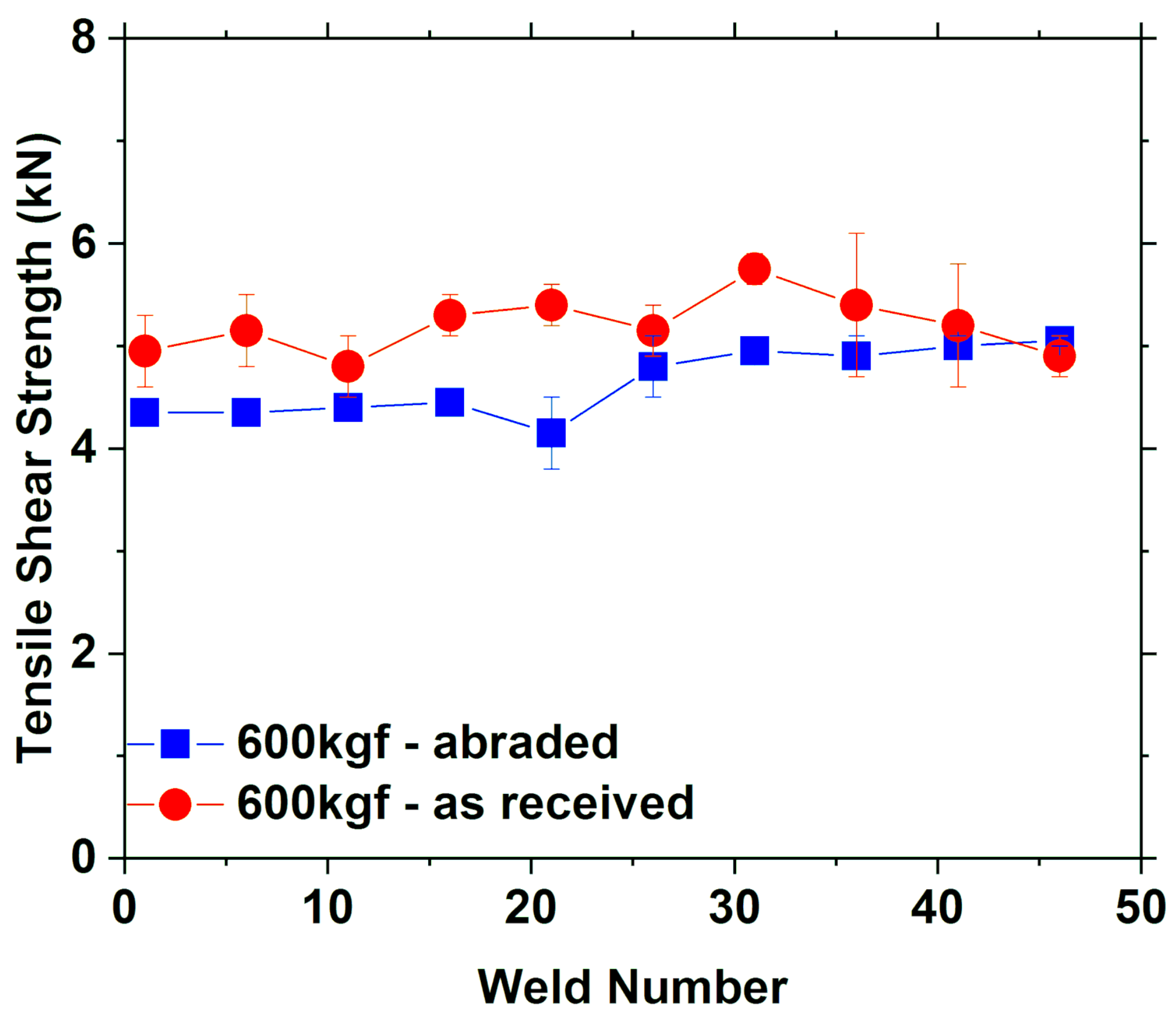
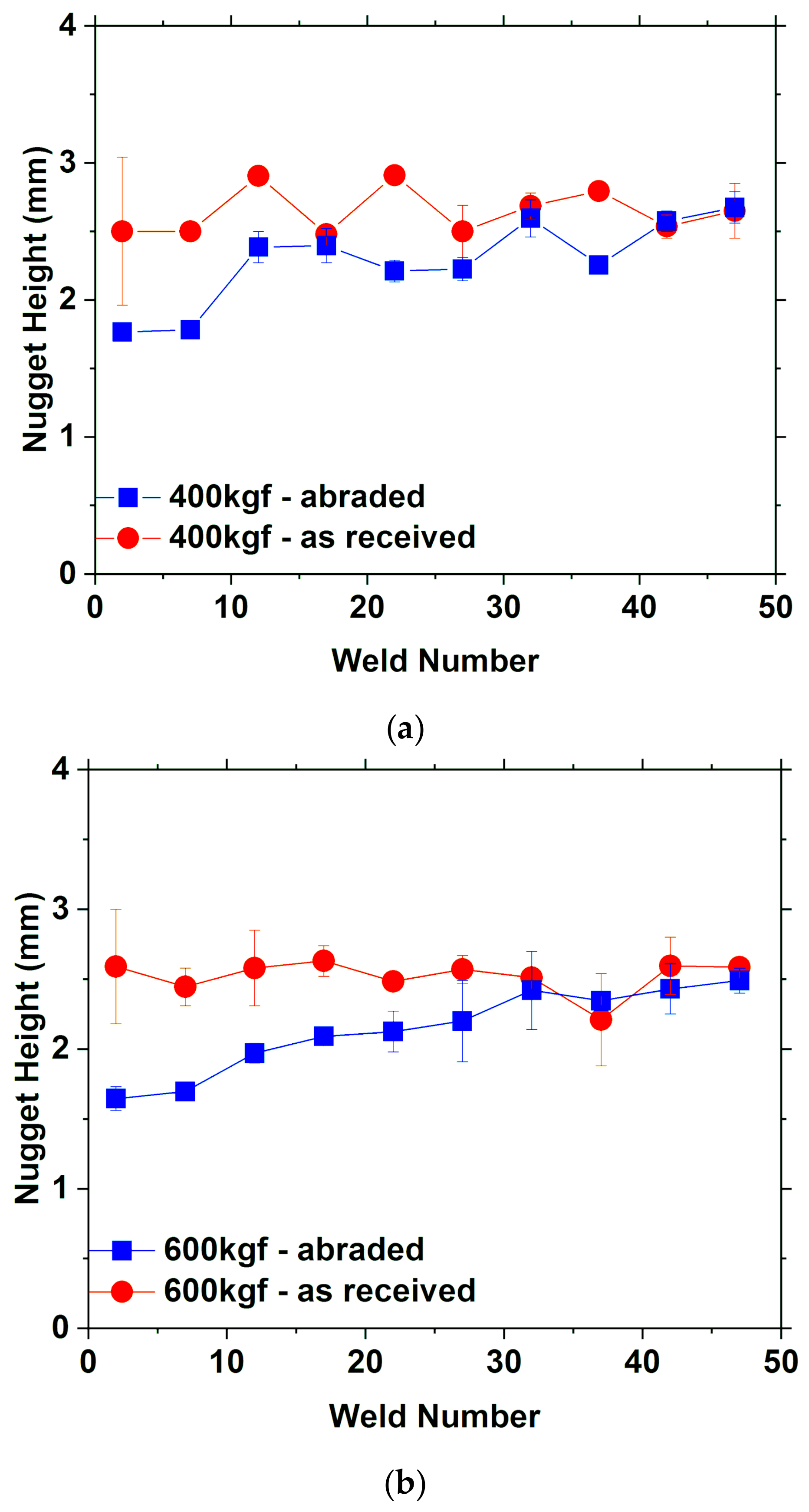
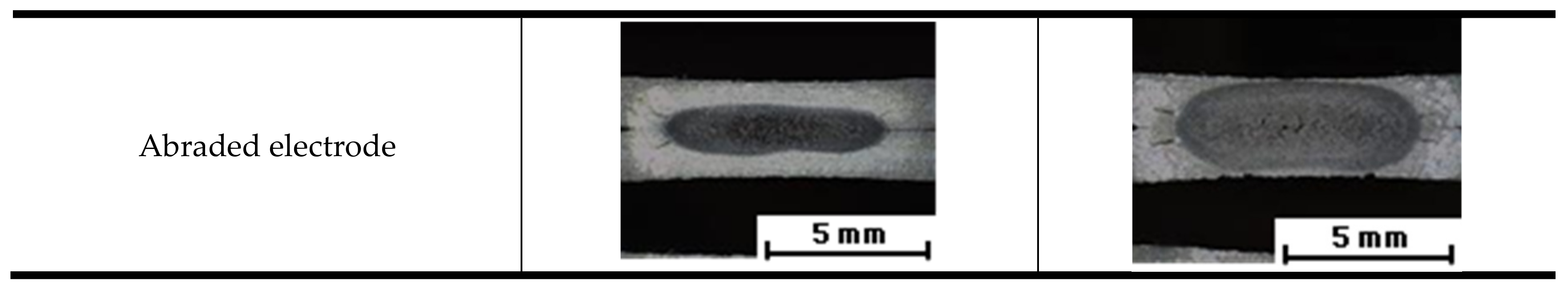
3.1. Nugget Size and Tensile Shear Strength
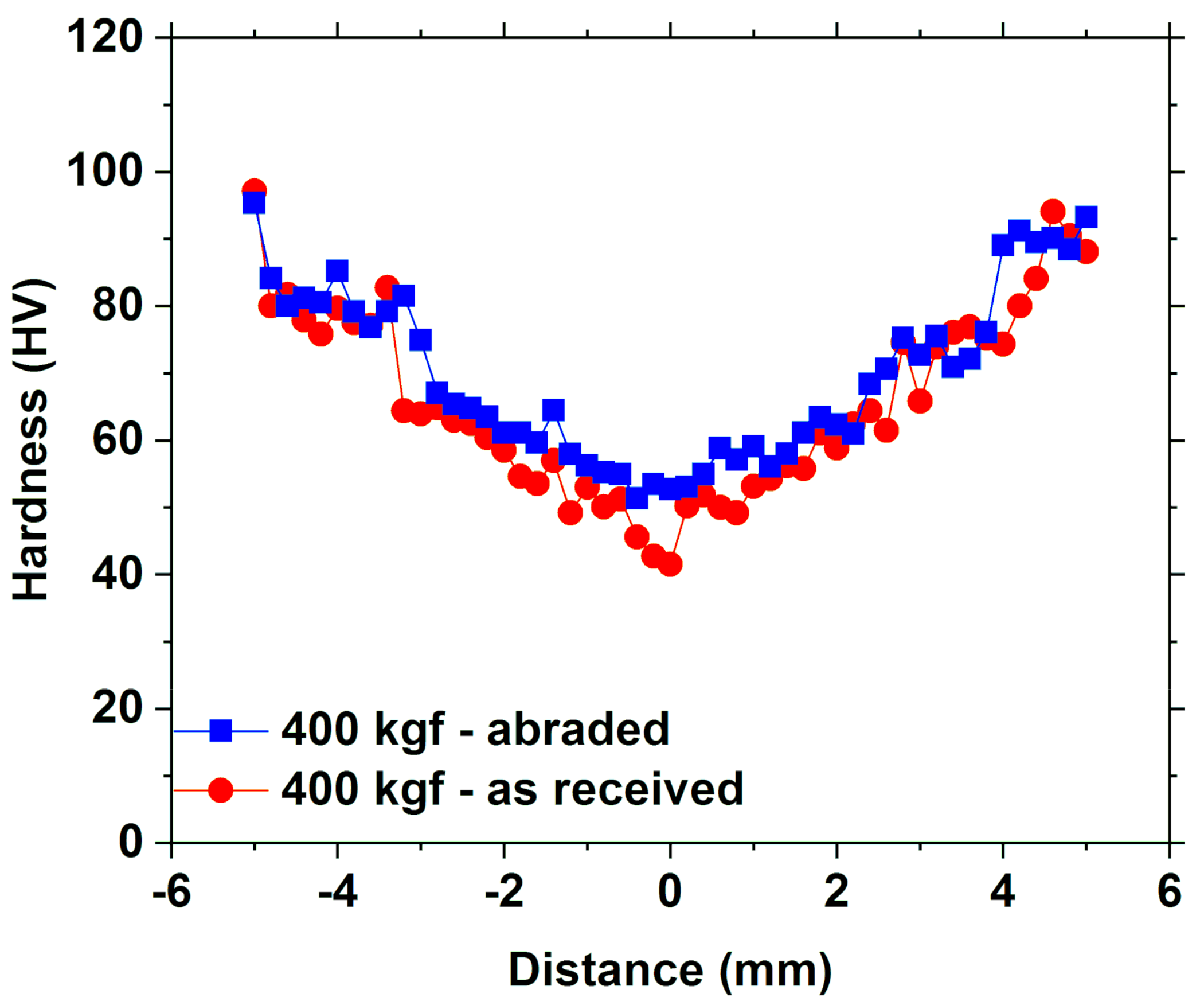
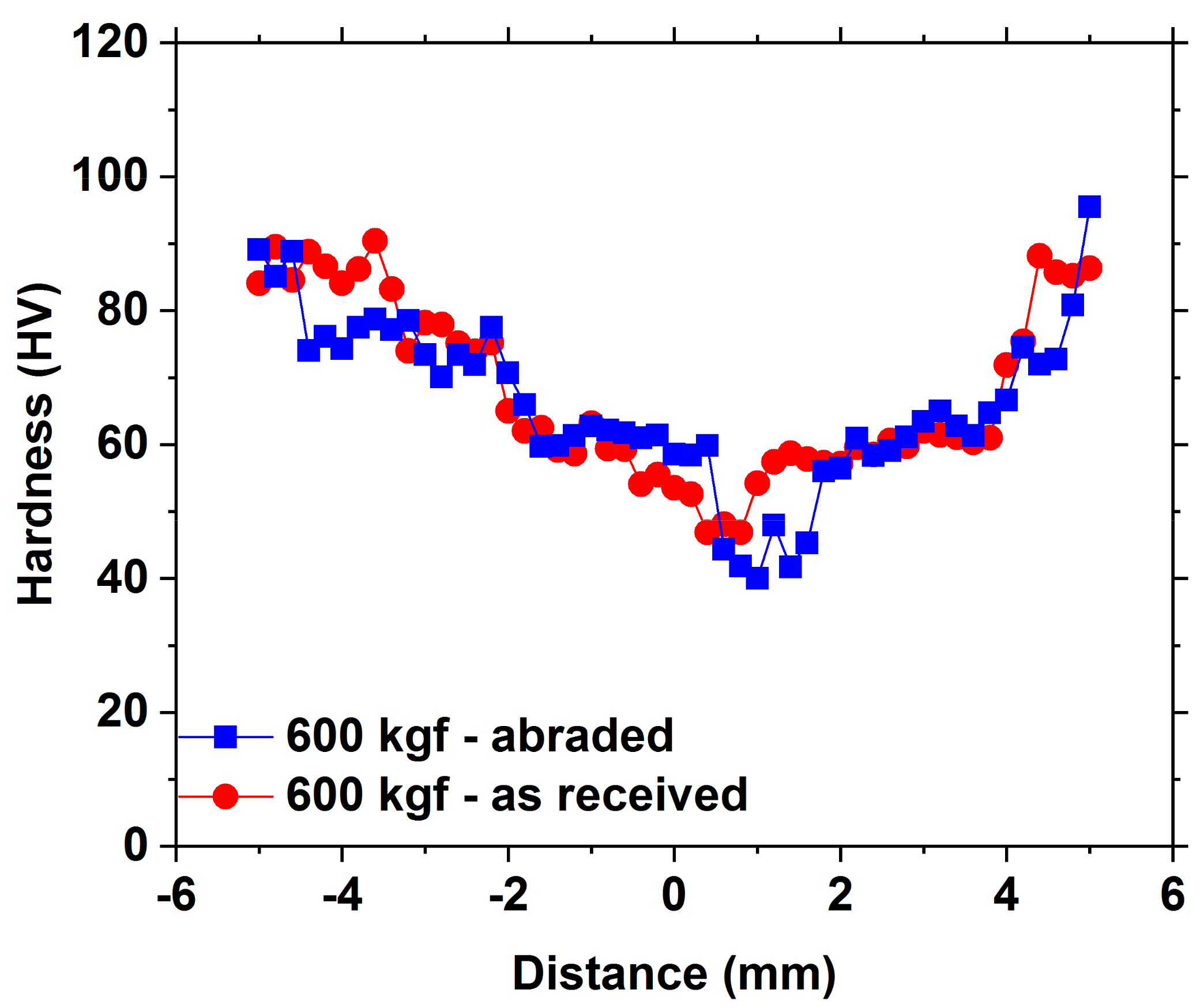
3.2. Hardness
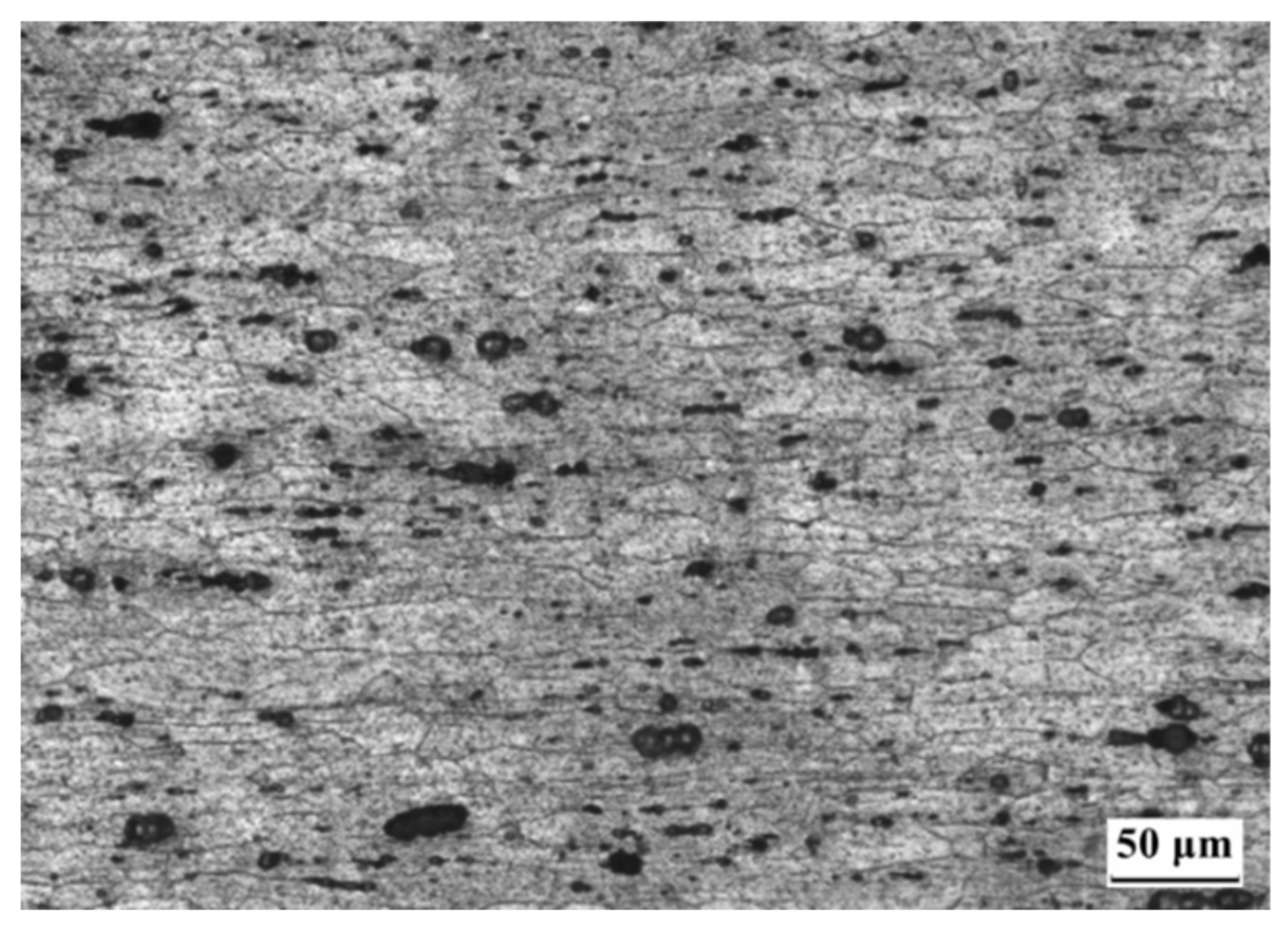
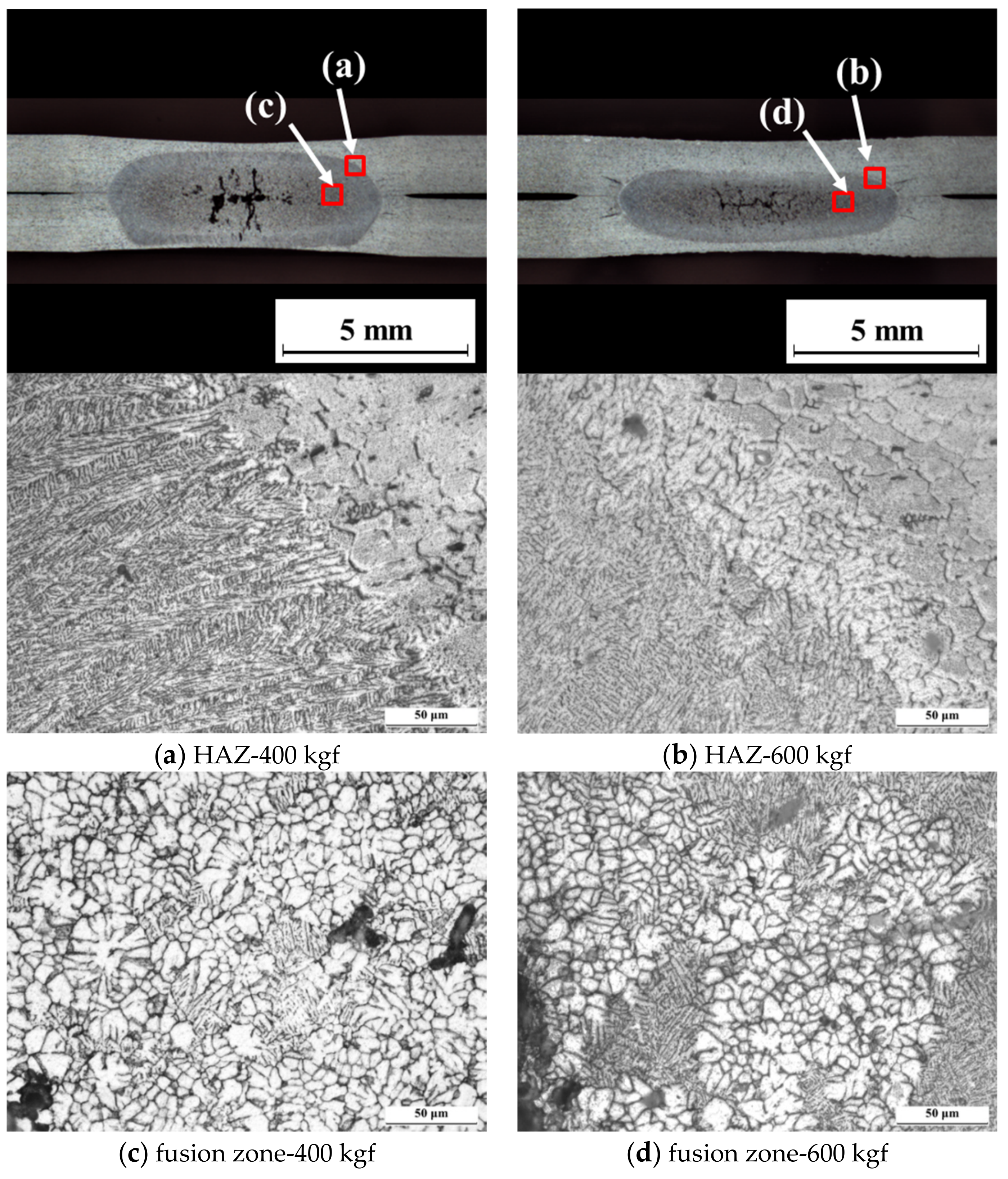
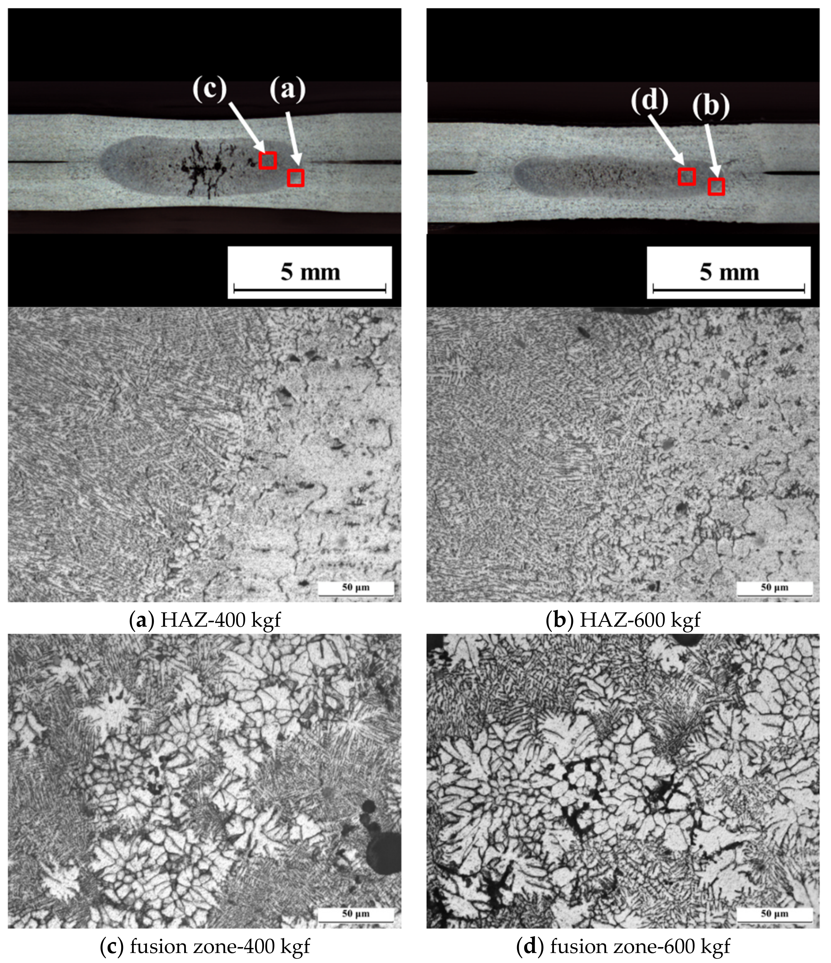
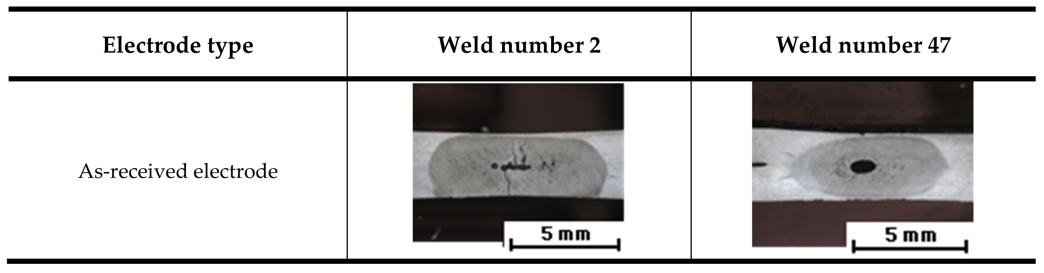
3.3. Microstructure
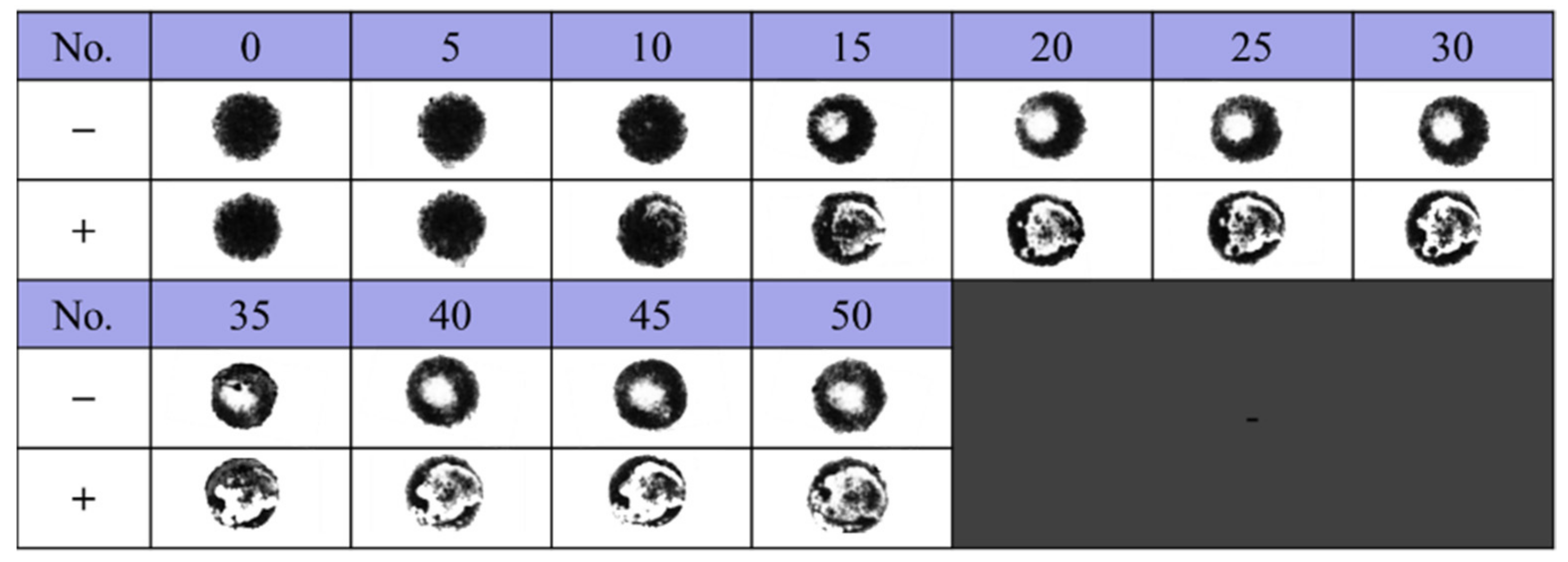
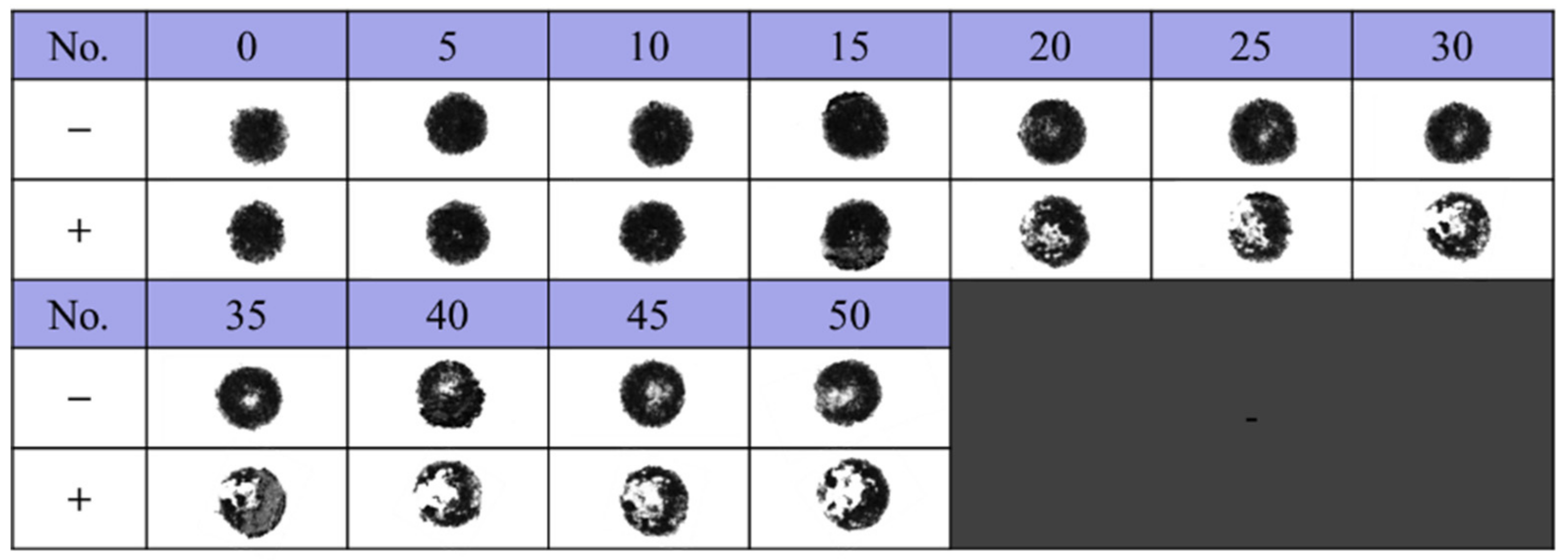
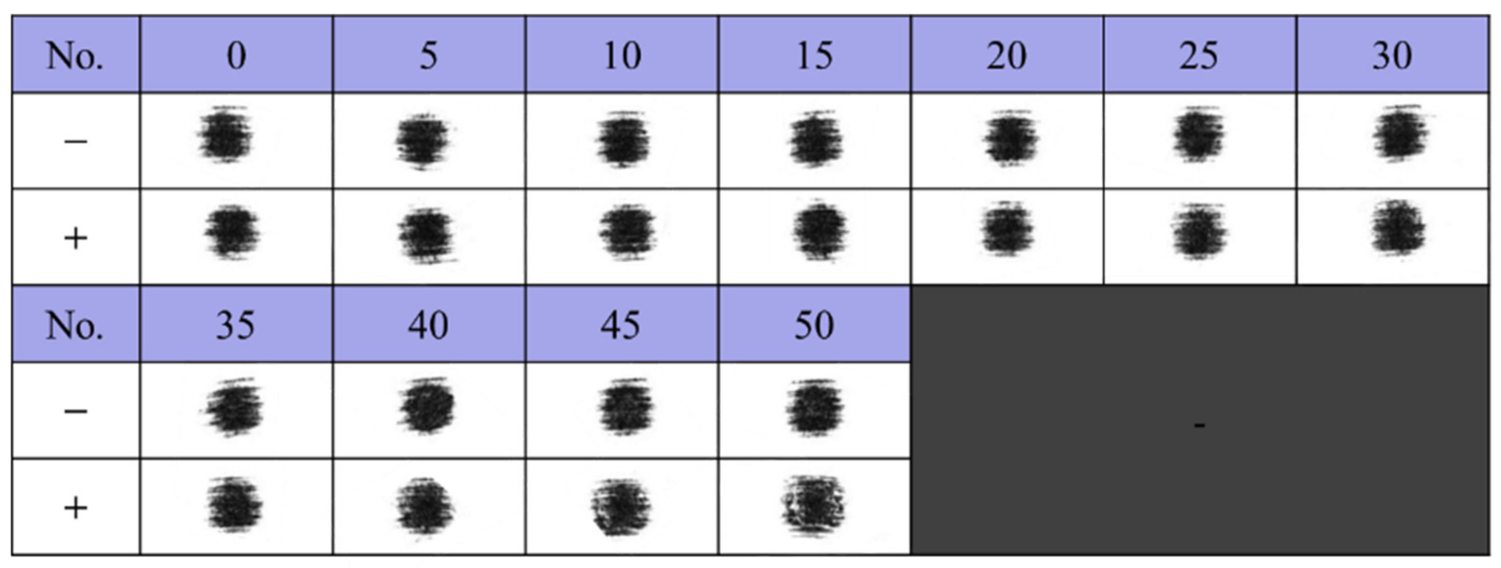
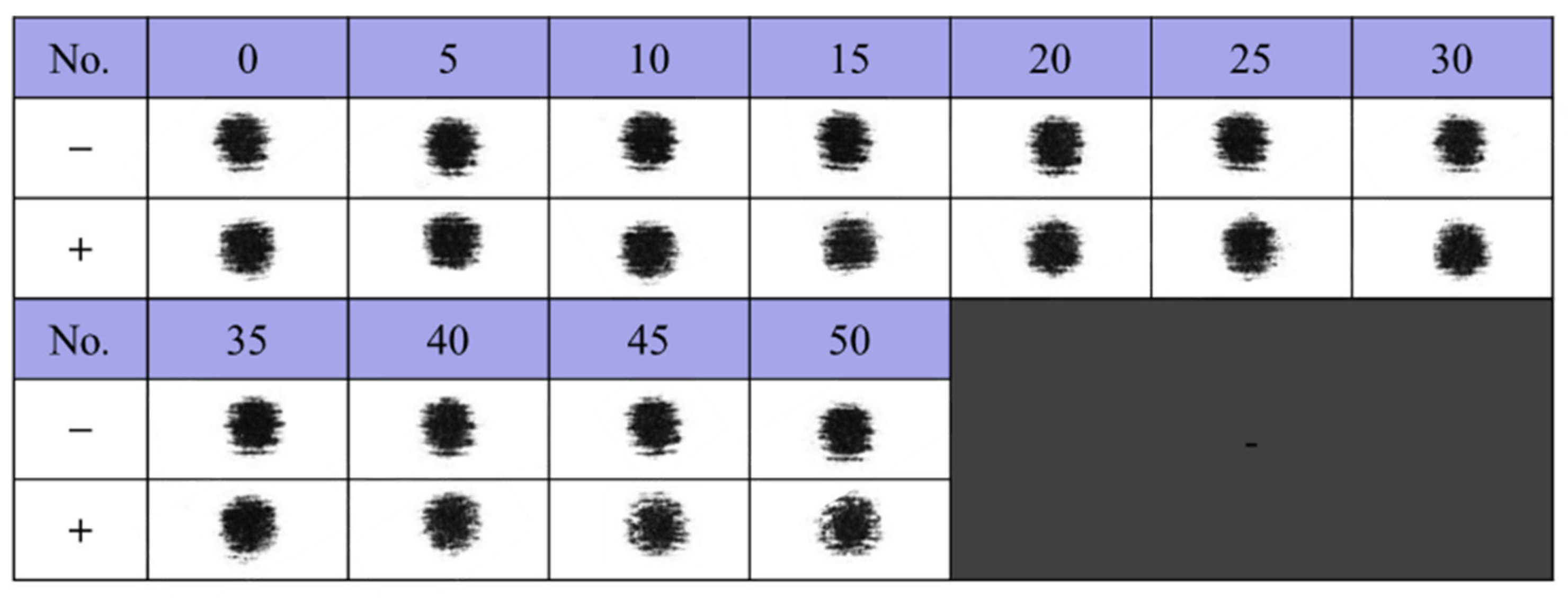
3.4. Continuous Welding Process and Electrode Sticking
4. Conclusions
- (1)
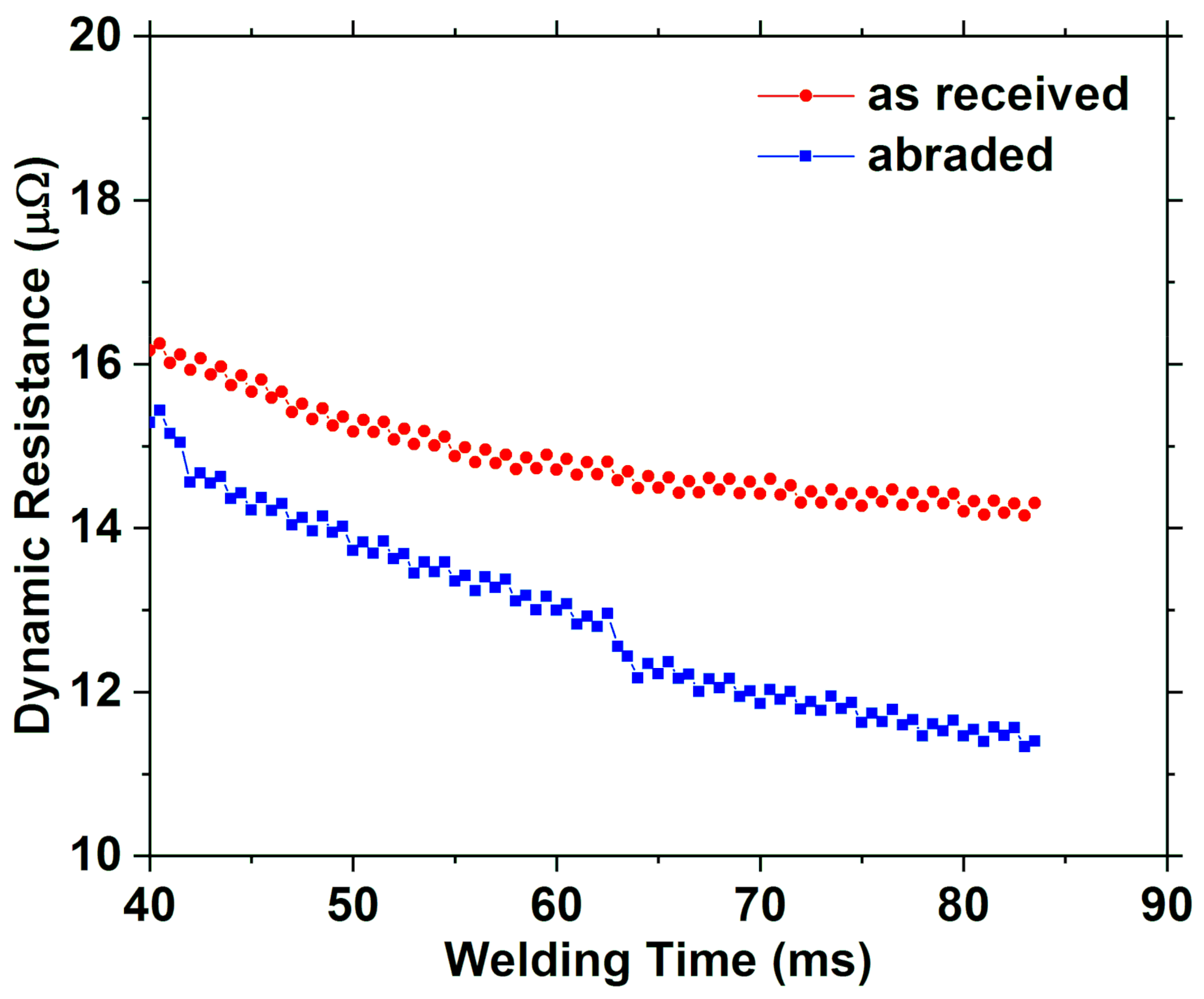
- The electrode surface roughness (observed for the abraded electrode) allowed to destroy the oxide layer on the surface of the base material. As a result, the resistance heat between the base material and the electrode was reduced during resistance spot welding, so that the nugget size of the weld was reduced, and the tensile shear strength was reduced.
- (2)
- In the case of the as-received electrode, the sticking was slightly improved at a high electrode force, although it was very severe compared to that of the abraded electrode. In the case of the abraded electrode, the sticking was not affected by the electrode force. Therefore, the effect on the sticking of the electrodes according to the electrode force was more pronounced in the as-received electrode.
- (3)
- During the continuous RSW process using the abraded electrode with surface roughness, sticking of the electrode tip was delayed as compared to the as-received electrode. The sticking mainly occurred on the (+) electrode face because of thermoelectric effects such as the Peltier effect.
- (4)
- The increase of electrode surface roughness during the continuous RSW process reduced the sticking of the electrode by slowing the growth of the nugget in the thickness direction.
Author Contributions
Funding
Conflicts of Interest
References
- Carle, D.; Blount, G. The Suitability of Aluminium as an Alternative Material for Car Bodies. Mater. Des. 1999, 20, 267–272. [Google Scholar] [CrossRef]
- Kim, G.-C.; Hwang, I.; Kang, M.; Kim, D.; Park, H.; Kim, Y.-M. Effect of welding time on resistance spot weldability of aluminum 5052 alloy. Met. Mater. Int. 2019, 25, 207–218. [Google Scholar] [CrossRef]
- Auhl, J.R.; Patrick, E.P. A fresh look at resistance spot welding of aluminum automotive components. SAE Trans. J. Mater. Manuf. 1994, 103, 36–48. [Google Scholar]
- Ronnhult, T.; Rilby, U.; Olefjord, I. The surface state and weldability of aluminium alloys. Mater. Sci. Eng. 1980, 42, 329–336. [Google Scholar] [CrossRef]
- Li, Z.; Hao, C.; Zhang, J.; Zhang, H. Effects of sheet surface conditions on electrode life in resistance welding aluminum. Weld. J. 2007, 86, 81–89. [Google Scholar]
- Han, L.; Thornton, M.; Shergold, M. A comparison of the mechanical behavior of self-piercing riveted and resistance spot welded aluminum sheets for the automotive industry. Mater. Des. 2010, 31, 1457–1467. [Google Scholar] [CrossRef]
- Sigler, D.R.; Carlson, B.E.; Janiak, P. Improving aluminum resistance spot welding in automotive structures. Weld. J. 2013, 92, 64–72. [Google Scholar]
- Kang, J.; Chen, Y.; Sigler, D.; Carlson, B.E.; Wilkinson, D.S. Fatigue behavior of dissimilar aluminum alloy spot Welds. Procedia Eng. 2015, 114, 149–156. [Google Scholar] [CrossRef][Green Version]
- Mueller, M.; Cramer, H.; Bschorr, T. Optimization of the electrode processing methodlogy for resistance spot welding of aluminium. Adv. Mater. Res. 2013, 814, 147–158. [Google Scholar] [CrossRef]
- Jo, H.; Kim, Y.M.; Kang, M.; Kim, D. Effects of electrode face radius and force on resistance spot weldability of aluminum alloy 6061. J. Weld. Join. 2018, 12, 46–51. [Google Scholar] [CrossRef]
- Balder, T.C. Influence of the peltier effect in resistance welding. Philips Tech. Rev. 1958, 20, 188–192. [Google Scholar]


| Material | Chemical Composition (wt. %) | Mechanical Properties | |||||||||
|---|---|---|---|---|---|---|---|---|---|---|---|
| Al 6061-T6 | Si | Fe | Cu | Mn | Mg | Cr | Ti | Al | yield strength (MPa) | tensile strength (MPa) | Elongation (%) |
| 0.59 | 0.39 | 0.25 | 0.07 | 1.12 | 0.19 | 0.03 | Bal. | 298 | 338 | 11 | |
| Electrode Surface Type | Electrode Force (kgf) | Welding Current (kA) | Welding Time (ms) |
|---|---|---|---|
| as-received abraded | 400 600 | 32 36 | 83.5 |
| Electrode Surface Type | Electrode Force (kgf) | Welding Current (kA) | Welding Time (ms) | Tensile Shear Strength (kN) | Nugget Size (mm) |
|---|---|---|---|---|---|
| as-received | 400 | 32 | 83.5 | 4.99 ± 0.08 | 7.20 ± 0.32 |
| 600 | 36 | 83.5 | 4.89 ± 0.24 | 8.20 ± 0.04 | |
| abraded | 400 | 32 | 83.5 | 4.37 ± 0.02 | 7.04 ± 0.01 |
| 600 | 36 | 83.5 | 4.23 ± 0.02 | 6.90 ± 0.02 |
© 2019 by the authors. Licensee MDPI, Basel, Switzerland. This article is an open access article distributed under the terms and conditions of the Creative Commons Attribution (CC BY) license (http://creativecommons.org/licenses/by/4.0/).
Share and Cite
Jo, H.; Kim, D.; Kang, M.; Park, J.; Kim, Y.-M. Effects of Surface Roughness and Force of Electrode on Resistance Spot Weldability of Aluminum 6061 Alloy. Appl. Sci. 2019, 9, 3958. https://doi.org/10.3390/app9193958
Jo H, Kim D, Kang M, Park J, Kim Y-M. Effects of Surface Roughness and Force of Electrode on Resistance Spot Weldability of Aluminum 6061 Alloy. Applied Sciences. 2019; 9(19):3958. https://doi.org/10.3390/app9193958
Chicago/Turabian StyleJo, Hyeonggeun, Dongcheol Kim, Munjin Kang, Junhong Park, and Young-Min Kim. 2019. "Effects of Surface Roughness and Force of Electrode on Resistance Spot Weldability of Aluminum 6061 Alloy" Applied Sciences 9, no. 19: 3958. https://doi.org/10.3390/app9193958
APA StyleJo, H., Kim, D., Kang, M., Park, J., & Kim, Y.-M. (2019). Effects of Surface Roughness and Force of Electrode on Resistance Spot Weldability of Aluminum 6061 Alloy. Applied Sciences, 9(19), 3958. https://doi.org/10.3390/app9193958