Article

Optimizing Single-Shot Coherent Power-Spectrum Scattering Imaging Adaptively by Tuning Feedback Coefficient for Practical Exposure Conditions

1
College of Computer and Communication Engineering, Changsha University of Science and Technology, Changsha 410114, China
2
College of Liberal Arts and Sciences, National University of Defense Technology, Changsha 410073, China
*
Author to whom correspondence should be addressed.
Appl. Sci. 2019, 9(18), 3676; https://doi.org/10.3390/app9183676
Submission received: 31 July 2019 / Revised: 26 August 2019 / Accepted: 27 August 2019 / Published: 5 September 2019
(This article belongs to the Special Issue Advanced Ultrafast Imaging)

Abstract

:
With only one piece of the power-spectrum pattern, the single-shot coherent power-spectrum imaging can provide a clear object image for real-time applications even if the object is hidden by opaque scattering media, in which the feedback coefficient β value for the reconstruction with least retrievals and fastest speed has to be pre-estimated through time-consuming iterative loops. Here we report a method for estimating the optimal β value from the captured raw power-spectrum images adaptively to optimize the single-shot coherent power-spectrum imaging for practical exposure conditions. The results demonstrate that, based on exposure level analysis of the captured raw power-spectrum images even of underexposure, moderate exposure, and overexposure cases, the β value could be quickly determined with a compact expression for the algorithm to achieve clear reconstruction output efficiently. The proposed method helps to push ahead of the coherent diffractive imaging devices for real-time imaging through turbid mediums in Artificial Intelligence (AI), driving assistance, and flight assistance applications.

1. Introduction

Achieving clear images of the objects embedded in turbid media has always been a challenge for biomedicine, nanotechnology and underwater imaging [1,2,3,4,5,6,7], as the scattering medium usually causes irregular scattering interference beams [8]. Though non-destructive coherent imaging methods [9,10] with angle scanning and additional holographic reference light beam can help to solve the problem somewhat, the practical complex operations still hinder their real-time imaging applications. Tang et al. proposed a single-shot coherent power-spectrum imaging method for imaging objects hidden by opaque scattering media [11] without angle scanning and additional holographic reference light, which may be a promising method for real-time scattering imaging.
Tang’ s method could reconstruct object images hidden in scattering media with only a piece of the single-shot coherent power-spectrum pattern, which is a good attempt in real-time scattering imaging. However, for the practical captured power-spectrum pattern, the object images cannot always be successfully reconstructed quickly. The main factor causing this result is the setting of experimental conditions, including the roughness of the scattering layer, the accuracy of the power-spectrum pattern, the exposure time of the acquisition spectrum, and so on. In terms of algorithm, the feedback coefficient β is an important value, which can reduce the iteration error and accelerate the convergence of the algorithm. Many researchers set the feedback coefficients as an empirical constant, but the value of β will greatly change the process of object reconstruction, its selection is closely related to the experimental conditions, current literature have not studied whether the feedback coefficients need to be adjusted when the experimental conditions are changed. The most significant variable affecting the scattering imaging process among the conditions is the exposure time. None of the above literature has studied the reconstruction effect with the power spectrum acquired with different exposure times, so no certain relationship between the feedback coefficient and exposure time has been uncovered, including Tang’ s work, which is only a feasibility experimental verification. The fact is, the feedback coefficient β value for the hybrid input-output (HIO) reconstruction algorithm has to be carefully selected from a wide range of 0.5–1.0 which Fienup suggested [12], and even go through 0.1–2.0, so as to achieve the optimum reconstruction, which seriously reduces the reconstruction efficiency. Actually, even under the same experimental conditions, the exposure levels of various captured power-spectrum patterns will be different for various camera’s exposure time settings, which then makes the information distribution of the patterns different. Therefore, the fixed single feedback coefficient β value cannot efficiently serve for the single-shot power-spectrum imaging method to reconstruct object images from the power-spectrum patterns with different exposures efficiently [13,14,15].
Herein, we find that the optimum β value is closely related to the exposure degree of the captured power-spectrum patterns, which is not always limited in the range of 0.5–1.0. Furthermore, we analyze the relationship between the β values and the exposure conditions, which will be described in detail as an equation in Section 4, so as to improve the single-shot coherent power-spectrum imaging method for different exposure conditions by selecting suitable β values adaptively. We found that, for the underexposure, moderate exposure and overexposure cases, the optimum β value could be quickly selected from various narrow ranges, which promotes the rapid and accurate object reconstruction.

2. Inconsiderateness in Previous Single-Shot Coherent Power-Spectrum Imaging Methods

By applying Tang’s single-shot power-spectrum imaging method for imaging a target hidden in an opaque scattering medium, with a fixed β value, we found that the reconstruction performance of various power-spectrum patterns captured with different exposure levels is different which usually occurs in practice, as shown in Figure 1. At the same time, we also show the power spectrum collected without a scattering layer in Figure 1(g1,g2) for comparison.
The images shown in the upper part of Figure 1(a1–f1), are the captured power-spectrum patterns of the character ‘5’ on a United States Air Force (USAF) 1951 resolution test chart, with the different exposure times of the camera. In the experiments, we made the illuminating laser power to be the same. In the reconstructions, we used the fixed β = 0.9, and the results are shown in the lower part of Figure 1, i.e., Figure 1(a2–f2), which are considered the best output for various patterns.
In order to check the effect of the value of the parameter β on the reconstruction output, we went through the feedback coefficient β in the range of 0.1–1.5 with intervals of 0.1 for various input patterns, to get the best reconstruction outputs, as shown in Table 1, Y denotes reconfigurability, N denotes non-reconfigurability. Y or N is determined by the following criteria with the normalized root-mean-square error (NRMS) [16] expressed in Equation (1), the threshold was set to NRMS = 0.03. We record the NRMS of each reconstructed image with the power spectrum under the same exposure condition at different β values as N [ β 1 , β 2 , β n ] , then calculate Δ i = N [ β i + 2 ] N [ β i ] , i [ 1 , n 2 ] , and find out the max value of Δ i . After this, we use the average of N [ β i + 2 ] and N [ β i ] corresponding to the maximal Δ i as the threshold of the successful reconstruction.
N R M S = [ x r | g k ( x ) | 2 x | g k ( x ) | 2 ] 1 / 2
The power-spectrum pattern captured at different exposure levels could reconstruct objects with suitable feedback coefficient β values. The suitable β values for different exposure level patterns are distinguished from each other. It should be pointed out that, when the input power-spectrum pattern size is 480 × 480, each reconstruction in Figure 1(a1–f1) took 13 min with a normal laptop (ASUS N75S, Intel (R) Core i7-2670QMCPU, 16G RAM) by going through the β value range of 0.1–1.5. Most of the time was spent was going through the wide β value range to find out the suitable value, which is much longer for larger size input power-spectrum pattern, hence, it hinders the real-time imaging applications. However, if the suitable β value can be pre-estimated properly, the reconstruction time is much shorter, which is only about 8 s for each successful reconstruction in Table 1. Therefore, pre-estimating the suitable β value for object image reconstruction is significant for the single-shot coherent power-spectrum scattering imaging in practical applications.

3. Exposure Level Estimation and Adaptive Selection of Suitable β Value

3.1. Exposure Level Estimation

We define four internals for the practical 8-bit image pixel value in the range of 0–255, i.e., a 1 (0–10), a 2 (11–150), a 3 (151–245), and a 4 (246–255). The figures shown in Figure 2a,c,e are taken by the camera with different exposure conditions for the same scene. From Figure 2a,e, we can intuitively find the loss of information in brighter or darker areas, while the information in Figure 2c is relatively complete and all objects in the figure can be seen clearly. In order to show how the pixel value distribution changes with exposure time, the interval proportion among the total pixel number is calculated to estimate the exposure level, Figure 2b,d,f are, respectively, the histograms of Figure 2a,c,e, and the estimation criterion is expressed as following Equation (2).
y = { 1 , a 1 > 0.1 0 , a 1 0 , a 2 + a 3 > 0.8 a n d a 4 0.1 1 , a 4 > 0.1
where a 1 , a 2 , a 3 and a 4 are in range of 0~1, y = 1 means underexposure; y = 0 means moderate exposure; and y = 1 means overexposure.
In practice, the exposure time of the camera and the different illumination will lead to many differences in the captured power-spectrum patterns. For the underexposure case, the corresponding gray histogram contains a large number of pixels with small gray value, as shown in Figure 2e,f. On the contrary, for the overexposure case, the number of high gray level pixels is be very large, and even many pixels are overflowed when limited to 255 in a large image area, as shown in Figure 2a,b. When the exposure is moderate, most of the pixels have a gray value around interval a 2 and a 3 [17], as shown in Figure 2c,d.

3.2. Adaptive Selection of Suitable β Value

In the reconstruction algorithm, our constraint is that the pixels must be non-negative, for pixels that violate the constraint, we use Equation (3) [18] to replace them. Among them, γ is the set of points which violates the object-domain constraints, β is a constant, which prevents the algorithm from falling into the local optimum points.
g k + 1 ( x ) = { g k ( x ) , x γ g k ( x ) β g k ( x ) , x γ
So, we change the points which violate the object-domain constraints, which use the second line of Equation (3). Suppose the k t h input g k ( x ) is a 3 × 3 matrix A. The output g k ( x ) is another 3 × 3 matrix B, hence, the part of violates the object-domain constraints (the pixel value must be non-negative) can be expressed as:
g k + 1 ( x ) = [ a 11 a 12 a 13 a 21 a 22 a 23 a 31 a 32 a 33 ] β [ b 11 b 12 b 13 b 21 b 22 b 23 b 31 b 32 b 33 ] = [ a 11 + β | b 11 | a 12 + β | b 12 | a 13 + β | b 13 | a 21 + β | b 21 | a 22 + β | b 22 | a 31 + β | b 32 | a 31 + β | b 31 | a 32 + β | b 32 | a 33 + β | b 33 | ]
Among them, ‘||’ is an absolute value symbol, each element of the matrix in Equation (4) is an independent positive proportion function. As a positive proportional coefficient, β determines the change of the whole iteration process. As β becomes larger, the multiple change of pixel value makes too much difference between the ( k + 1 ) t h and k t h inputs, which will lead to the instability of the whole system and fails to reconstruct the object image finally. Therefore, the β value should be selected carefully, a single β value cannot make all coherent power-spectrum patterns reconstruct clear objects, and there is a corresponding β interval for input g k ( x ) .
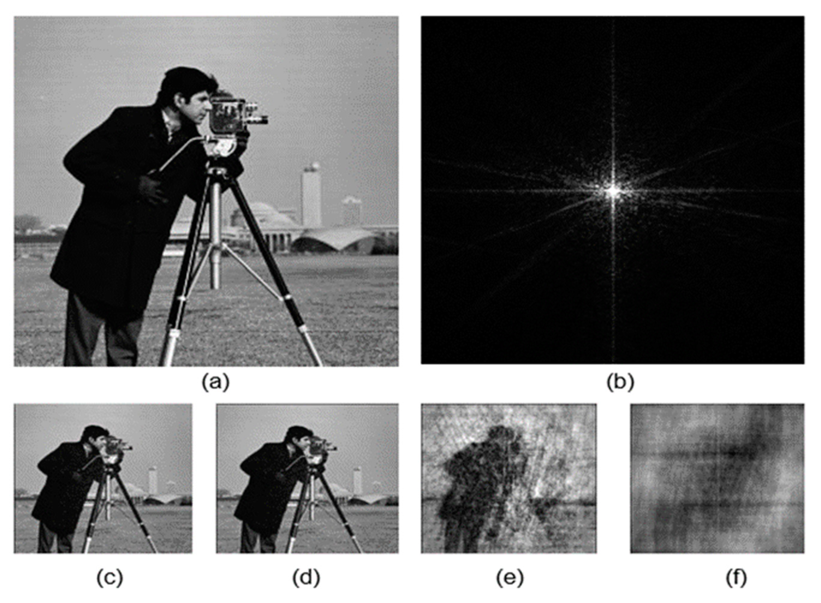
We validate the above conclusions by simulation. According to Equation (4), using the ‘cameraman’ image with a pixel size of 256 × 256 as the object to be reconstructed. The value of β traverses between 0.1–2 intervals and 0.01 intervals, and 100 iterations. According to the result of reconstruction, the object with β value in the range of 0.1–1.3 is very clear (the reconstruction effect can refer to Figure 3c. The recovery images appear blurred when β is bigger than 1.4, as shown in Figure 3e. When β is selected up to 2, no matter how many iterations are performed, the object images cannot be reconstructed successfully. The simulation results also show that β reconstruct a clear object not only in a the range of 0.5–1.0 proposed by Fienup. For the image of the ‘cameraman’, β is in the range of 0.1–1.3.
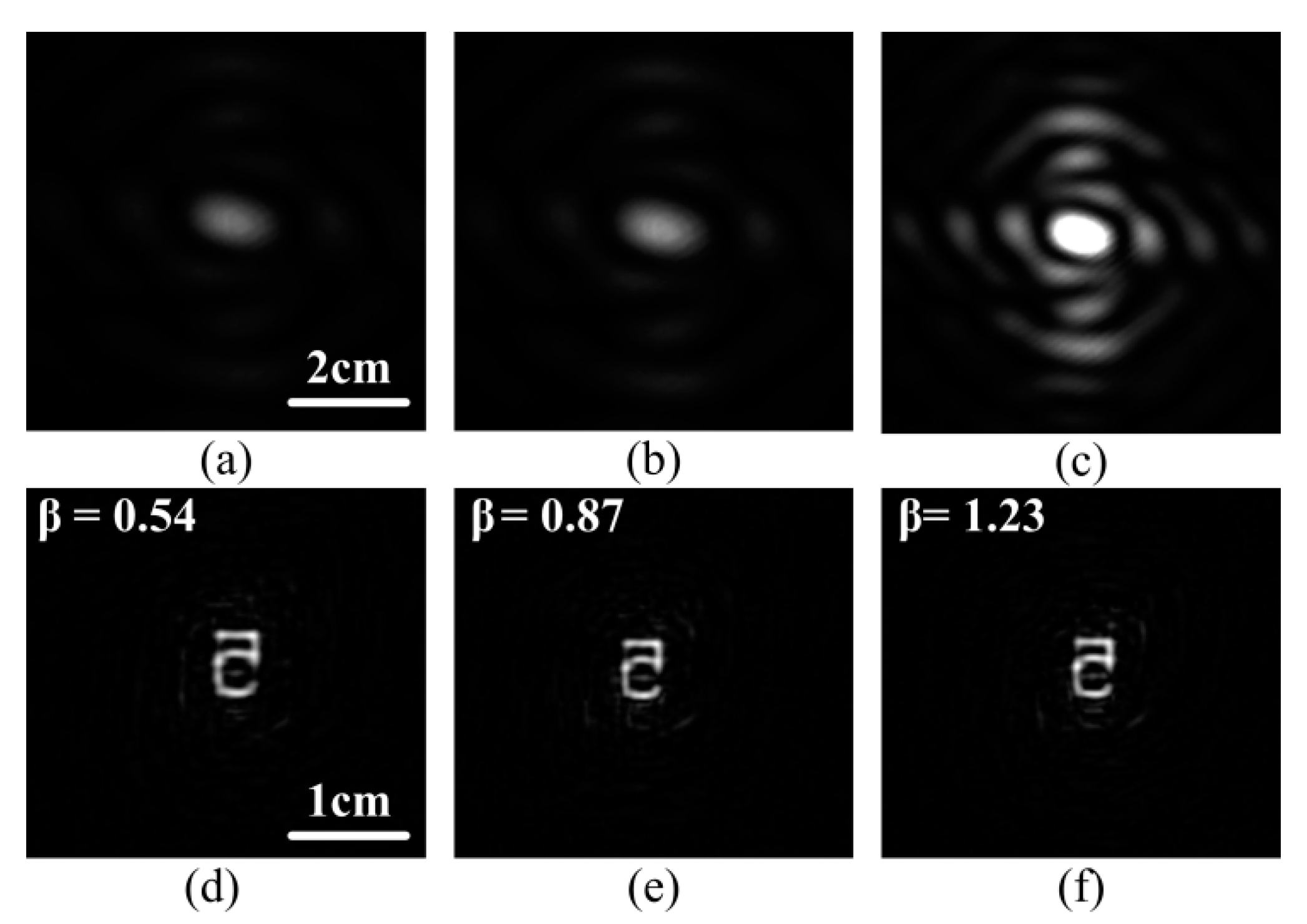
According to the above analysis, it is summarized as follows: in the single-shot coherent power-spectrum scattering imaging experiment, the exposure time of the camera determines the exposure degree of the collected power-spectrum. The exposure degree is also a reflection of the overall pixel value. The larger the exposure degree, the set of violations of the constraints needs to be adjusted by setting a larger β, making adjusted input is closer to the real object. So we choose to adjust the feedback coefficient β to solve the problem of acquiring single coherent power-spectrum scattering imaging with different exposure. We use the above conclusion to reconstruct the experimental power-spectrum (with the increase in the exposure level, the β value also needs to increase, accordingly). According to the β value set by prior knowledge, the reconstructed effect is shown in Figure 4a–c with a randomly selected power-spectrum pattern, Figure 4d–f are reconstructed by Figure 4a–c by setting different β values.

4. Experiment Results and Discussion

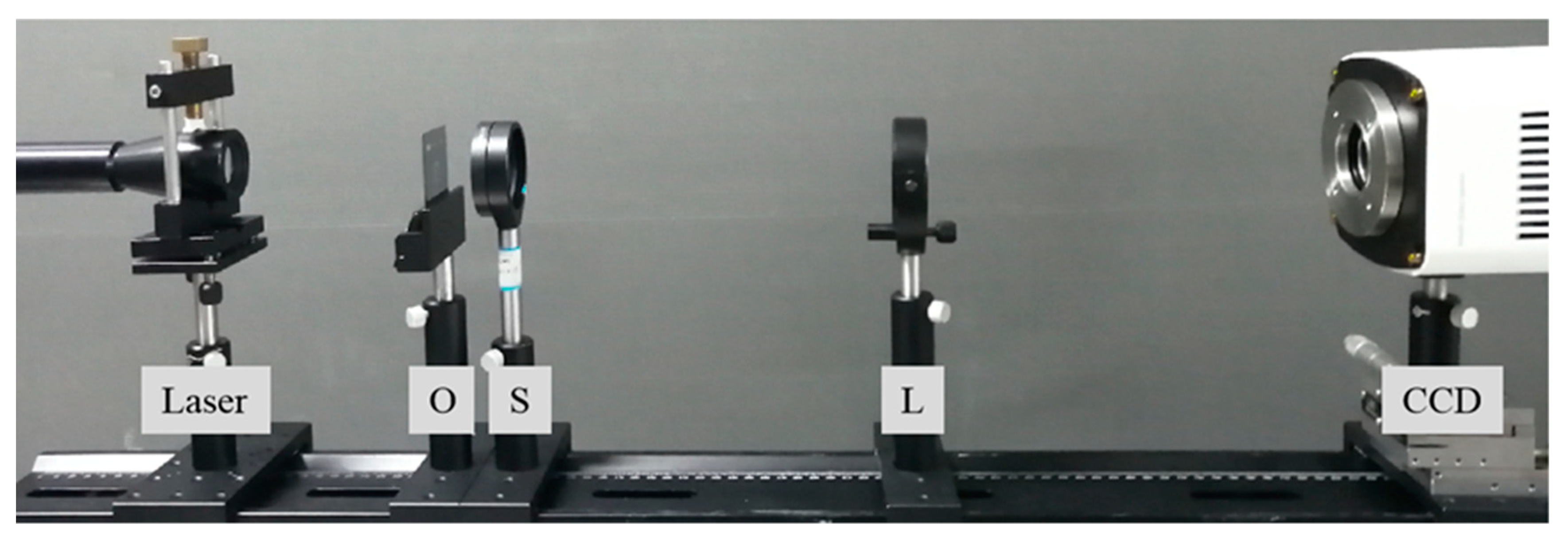
The experiment setup is shown in Figure 5, in which the coherent plane-wave beam is generated by a He-Ne laser (λ = 632.8 nm), and an opaque scattering layer S is placed between the object and the Fourier lens L, the exposure level is controlled by adjusting exposure time of the camera.
With character ‘5’ on a USAF 1951 resolution test chart as the object, we collected 200 pieces of coherent power-spectrum patterns with exposure time ranged from 100 μs to 20,000 μs to cover underexposure, moderate exposure, and overexposure. We used NRMS to evaluate the termination condition and reconstructed effect of the iterative algorithm. For each power-spectrum pattern, the suitable β value for successful reconstruction is selected by going through 0–2 with interval 0.01 to get the minimum NRMS value. The suitable β values for the 200 power-spectrum patterns are shown in Figure 6.
It can be seen from Figure 6, that the optimal β values for various exposure level input patterns are different, with an increasing trend in 0.2–1.3 for underexposure, moderate exposure, and overexposure cases. According to the statistics, the optimal β values for underexposure, moderate exposure, and overexposure cases lay in the range of 0.3–0.8, 0.8–1.1, and 1.0–1.25 respectively, which could be expressed by a fitting expression, as shown in Equation (5).
β = b + 0.01 × i = 1 i = 4 R ( a i ) × M ( a i )
where, R ( a i ) represents the pixel number proportion of interval a i , M ( a i ) represents the median of interval a i , and b represents the bias set [−1:0] by the exposure state, b = 0 for underexposure or moderate exposure, otherwise, b set [−1:−0.7].
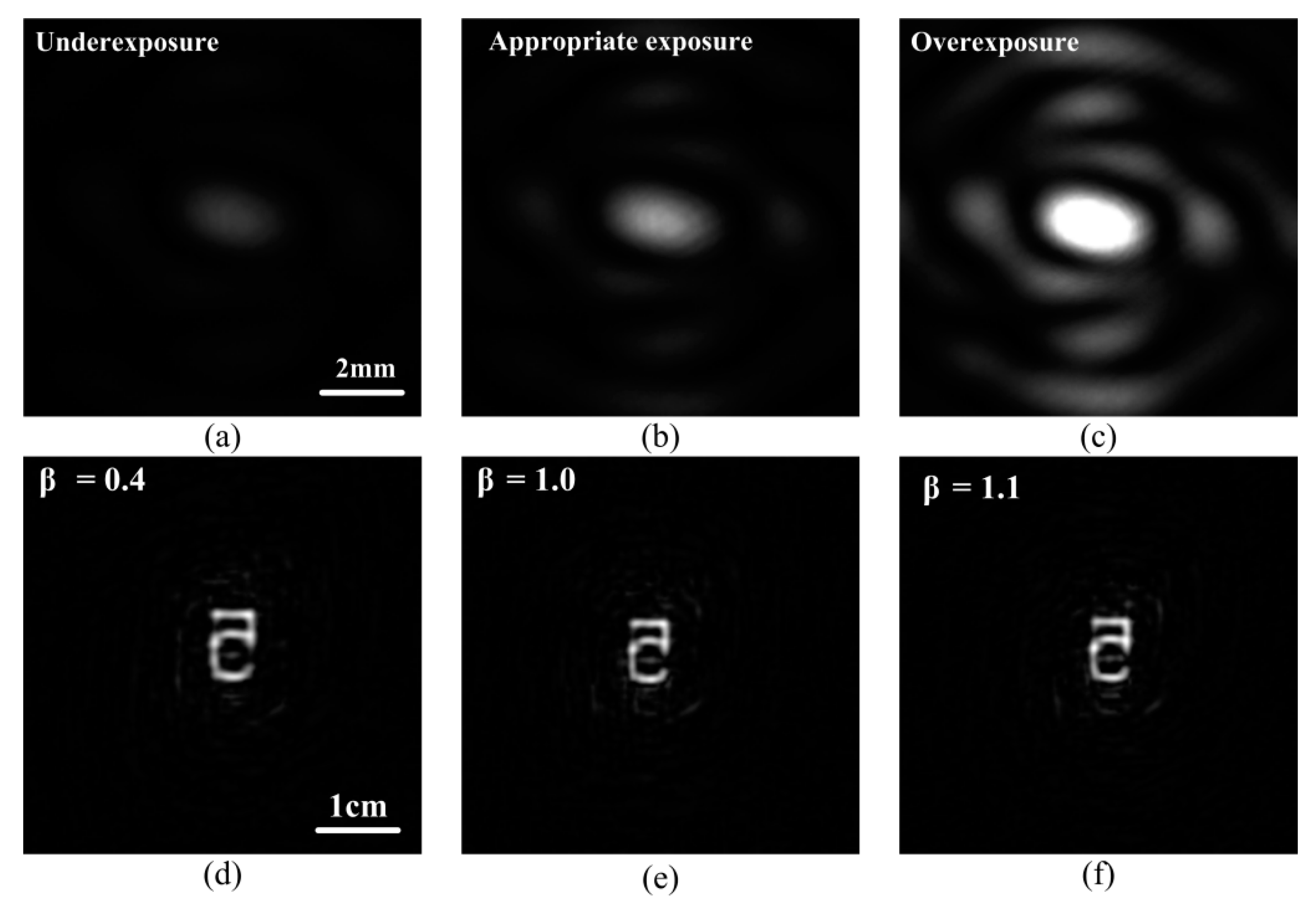
According to Equation (5), three power-spectrum patterns, in underexposure, moderate exposure, and overexposure states, respectively, are input for the reconstructions, and the corresponding results are shown in Figure 7. Obviously, for different exposure level cases, the reconstructions with corresponding different β values are clear. Furthermore, the time consumption for every reconstruction is no more than 9 s.
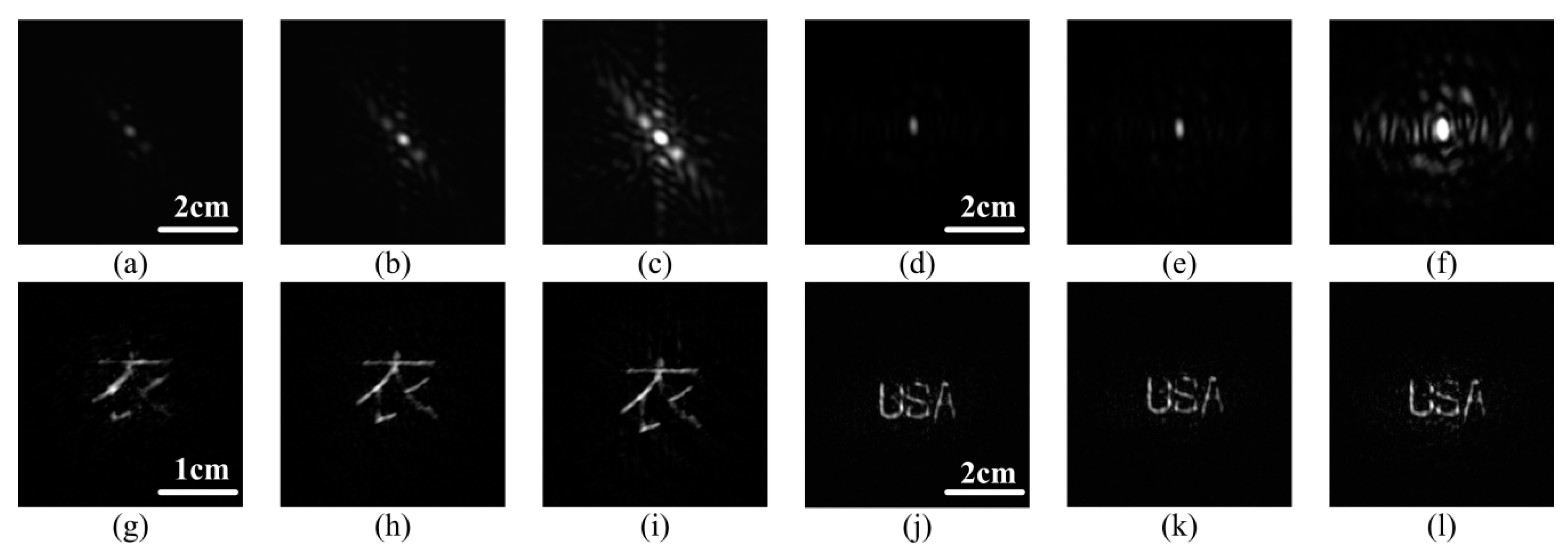
The other objects are also used for the experiments, as shown in Figure 8. For the practical power-spectrum patterns with different exposure levels, by choosing carefully the β value according to the given optimal β interval according to Equation (5), the images of the objects hidden by the scattering medium can be reconstructed well, which confirms the feasibility of the adaptive selection method of β value for the algorithm.

5. Conclusions

In summary, we analyze the influence of the exposure level of the power-spectrum pattern on the coherent power-spectrum scattering imaging method and propose a method of adjusting the feedback coefficient β adaptively. As a negative feedback coefficient for the reconstruction algorithm, β is used to reduce the error between the iteration output and the expected image, and finally, make the process work stably. The simulation results and the experimental results show that, for different exposures cases of captured power-spectrum patterns, the β values for the reconstruction algorithm should be changed, accordingly so as to achieve the optimum reconstructed output. For the three exposure cases of power-spectrum pattern capture, i.e., underexposure, moderate exposure, and overexposure, the β value should be selected in the range of 0.3–0.8, 0.6–1.1, and 1.0–1.25, respectively. Anyway, the β value selection guides will be helpful for the coherent diffraction imaging (CDI) with the hybrid input and output (HIO) algorithm, which could avoid the inappropriate β value for achieving successful object image reconstructions, and enhance real-time performance of coherent diffraction imaging. This method promotes the real-time imaging of single-shot coherent scattering imaging, and could also be used in fast variable-aperture Fourier ptychography scattering imaging [19].

Author Contributions

Conceptualization: W.W.; Methodology: Y.G. and W.T.; Software, W.Y.; Formal analysis: M.L.; Investigation, M.Z. and J.Q.; Writing—original draft preparation: Y.G.; writing—review and editing: X.L.; Funding acquisition: J.Z.

Funding

National Science Foundation of China (NSFC) (61070040, 61108089, 61205087, 61107005), 973 Program (613192), Advance Research Project (7301506), Hunan Provincial Natural Science Foundation of China (805297133191), Education Department of Hunan Province (17C0043), Hunan Provincial Natural Science Fund (2019JJ80105).

Acknowledgments

The authors acknowledge assistance from Meicheng Fu and Xiaochun Wang.

Conflicts of Interest

The authors declare no conflict of interest.

References

  1. Freudiger, C.W.; Min, W.; Saar, B.G.; Lu, S.; Holtom, G.R.; He, C.; Tsai, J.C.; Kang, J.X.; Xie, S. Label-free biomedical imaging with high sensitivity by stimulated raman scattering microscopy. Science 2008, 322, 1857. [Google Scholar] [CrossRef] [PubMed]
  2. Krafft, C.; Schie, I.W.; Meyer, T.; Schmitt, M.; Popp, J. Developments in spontaneous and coherent Raman scattering microscopic imaging for biomedical applications. Chem. Soc. Rev. 2016, 45, 1819–1849. [Google Scholar] [CrossRef] [PubMed]
  3. Patel, C.; Steuwe, S.; Reichelt, S.; Mahajan. Coherent anti-stokes raman scattering for label-free biomedical imaging. J. Opt. 2013, 15, 2897–2903. [Google Scholar] [CrossRef]
  4. Reginald, E.; Sunil, K. Laser transport through thin scattering layers. Appl. Opt. 2010, 49, 358. [Google Scholar]
  5. Wu, P.; Liang, Z.; Zhao, X.; Su, L.; Song, L. Lensless wide-field single-shot imaging through turbid media based on object-modulated speckles. Appl. Opt. 2017, 56, 3335. [Google Scholar] [CrossRef]
  6. Nagar, H.; Dekel, E.; Kasimov, D.; Roichman, Y. Non-diffracting beams for label-free imaging through turbid media. Opt. Lett. 2018, 43, 190. [Google Scholar] [CrossRef]
  7. Katz, E.S.; Silberberg, Y. Looking around corners and through thin turbid layers in real time with scattered incoherent light. Nat. Photon. 2012, 6, 549–553. [Google Scholar] [CrossRef]
  8. Bertolotti, J.; Van Putten, E.G.; Blum, C.; Lagendijk, A.; Vos, W.L.; Mosk, A.P. Non-invasive imaging through opaque scattering layers. Nature 2015, 491, 232–234. [Google Scholar] [CrossRef] [PubMed]
  9. Hsieh, C.L.; Ye, P.; Grange, R.; Laporte, G.; Psaltis, D. Imaging through turbid layers by scanning the phase conjugated second harmonic radiation from a nanoparticle. Opt. Exp. 2010, 18, 20723–20731. [Google Scholar] [CrossRef] [PubMed] [Green Version]
  10. Singh, K.; Naik, D.N.; Pedrini, G.; Takeda, M.; Osten, W. Looking through a diffuser and around an opaque surface: A holographic approach. Opt. Exp. 2014, 22, 7694–7701. [Google Scholar] [CrossRef] [PubMed]
  11. Tang, W.; Yang, J.; Yi, W.; Nie, Q.; Zhu, J.; Zhu, M.; Guo, Y.; Li, M.; Li, X.; Wang, W. Single-shot coherent power-spectrum imaging of objects hidden by opaque scattering media. Appl. Opt. 2019, 58, 1033–1039. [Google Scholar] [CrossRef]
  12. Fienup, J.R.; Wackerman, C.C. Phase-retrieval stagnation problems and solutions. J. Opt. Soc. Am. A 2008, 3, 1897. [Google Scholar] [CrossRef]
  13. Minkevich, M.; Köhl, T.B. Improved success rate and stability for phase retrieval by including randomized overrelaxation in the hybrid input output algorithm. Opt. Exp. 2012, 20, 17093–17106. [Google Scholar] [Green Version]
  14. Shi, L.; Wetzstein, G.; Lane, T.J. A flexible phase retrieval framework for flux-limited coherent X-ray imaging. arXiv 2016, arXiv:1606.01195. [Google Scholar]
  15. Rd, T.R.; Hyland, D. Mitigating the effect of noise in the hybrid input-output method of phase retrieval. Appl. Opt. 2013, 52, 3031–3037. [Google Scholar]
  16. Fienup, J.R.; Feldkamp, G.B. Astronomical imaging by processing stellar speckle interferometry data. Proc. SPIE Int. Soc. Opt. Eng. 1980, 243, 95–102. [Google Scholar]
  17. Zhang, H.; Cao, J.; Tang, L.; Wang, H. A new algorithm for auto-exposure based on the analogy histogram. In Proceedings of the 2011 Seventh International Conference on Computational Intelligence and Security, Hainan, China, 3–4 December 2011. [Google Scholar]
  18. Fienup, J.R. Reconstruction of an object from the modulus of its Fourier transform. Opt. Lett. 1978, 3, 27–29. [Google Scholar] [CrossRef] [PubMed]
  19. Tang, W.; Guo, Y.; Yi, W.; Yang, J.; Zhu, J.; Wang, W.; Li, X. A robust fast variable-aperture Fourier ptychography. Opt. Commun. 2019, 443, 144–149. [Google Scholar] [CrossRef]
Figure 1. The reconstruction results from various power-spectrum patterns with fixed β = 0.9. (a1f1) are power-spectrum patterns captured with exposure times of 3000 μs, 4000 μs, 6000 μs, 10,000 μs, 12,000 μs, and 20,000 μs, respectively; (a2f2) are the results reconstructed from (a1f1) by 100 iterations, (g1,g2) represent the power spectrum with and without scattering media, respectively. (b1f1) has the same scale bar as (a1); (b2f2) has the same scale bar as (a2); (g1) has the same scale bar as (g2).
Applsci 09 03676 g001
Figure 2. Pixel interval rate for different exposure degrees. a 1 , the pixel value range of 0–10; a 2 , the pixel value range of 11–150; a 3 , the pixel value range of 151–245; a 4 , the pixel value range of 245–255; (a,c,e) represent overexposure, moderate exposure, and underexposure cases, respectively; (b,d,f) are, respectively, the histograms of (a,c,e).
Applsci 09 03676 g002
Figure 3. The simulation results of the value of the traversing feedback coefficient β. (a) Original object image ‘cameraman’. (b) The power-spectrum pattern of the ‘Cameraman’ provided by fast Fourier transform (FFT). (c) The reconstructed object image with β = 0.1, (d) β = 0.7, (e) β = 1.5, and (f) β = 2.
Applsci 09 03676 g003
Figure 4. The object hidden in the scattering medium is reconstructed by adjusting the β value of the power-spectrum pattern with different exposure. (ac) are power-spectrum patterns captured at exposure times of 5000 μs, 7500 μs, 15,000 μs, respectively. (b,c) have the same scale bar as (a); (e,f) have the same scale bar as (d).
Applsci 09 03676 g004
Figure 5. Single-shot coherent power-spectrum scattering imaging experimental light path diagram. O represents object; S represents a scattering layer (Thorlabs DG10-600-MD); L represents Fourier transform lens.
Applsci 09 03676 g005
Figure 6. The optimum β value for the 200 reconstructions.
Applsci 09 03676 g006
Figure 7. Reconstruction results for different exposure levels and β values. (b,c) have the same scale bar as (a); (e,f) have the same scale bar as (d).
Applsci 09 03676 g007
Figure 8. Reconstruction results for other objects. (ac) and (df) are the power-spectrum patterns of the underexposure, moderate exposure, and overexposure, respectively; (gi) are the results for (ac) reconstruction; (jl) are the results for (df). (b) and (c) have the same scale bar as (a); (e,f) have the same scale bar as (d); (h,i) have the same scale bar as (g); (k,l) has the same scale bar as (j).
Applsci 09 03676 g008
Table 1. Reconstructing objects hidden in the scattering media by traversing β values. Y denotes reconfigurability; N denotes non-reconfigurability.
Captured Power-Spectrum Pattern(a1)(b1)(c1)(d1)(e1)(f1)
β = 0.1NNNNNN
β = 0.2YNNNNN
β = 0.3YYNNNN
β = 0.4YYNNNN
β = 0.5NYNNNN
β = 0.6YYNNNN
β = 0.7YYYYNN
β = 0.8YYYYNN
β = 0.9NYYYNN
β = 1.0NNYYYY
β = 1.1NNNNYY
β = 1.2NNNNYY
β = 1.3NNNNYY
β = 1.4NNNNYN
β = 1.5NNNNNN