Article

Effect of the Pillar Size on the Electrochemical Performance of Laser-Induced Silicon Micropillars as Anodes for Lithium-Ion Batteries

1
Department of Mechanical Engineering, Keio University, Hiyoshi 3-14-1, Kohoku-ku, Yokohama 223-8522, Japan
2
Department of Applied Chemistry, Faculty of Science and Technology, Keio University, Hiyoshi 3-14-1, Kohoku-ku, Yokohama 223-8522, Japan
3
Laser Processing Research Centre, School of Mechanical, Aerospace and Civil Engineering, The University of Manchester, Manchester M13 9PL, UK
*
Author to whom correspondence should be addressed.
Appl. Sci. 2019, 9(17), 3623; https://doi.org/10.3390/app9173623
Submission received: 5 August 2019 / Revised: 28 August 2019 / Accepted: 30 August 2019 / Published: 3 September 2019
(This article belongs to the Special Issue Advanced Materials for Rechargeable Lithium Batteries II)

Abstract

:

Featured Application

This study has demonstrated an efficient and environmentally friendly method of fabricating Si-based lithium-ion battery anodes from waste Si materials.

Abstract

Silicon micropillars with tunable sizes are successfully fabricated on copper foils by using nanosecond-pulsed laser irradiation and then used as anodes for lithium-ion batteries. The size of the silicon micropillars is manipulated by using different slurry layer thicknesses ranging from a few microns to tens of microns. The effects of the pillar size on electrochemical properties are thoroughly investigated. The smaller the pillars, the better the electrochemical performance. A capacity of 1647 mAh g−1 at 0.1 C current rate is achieved in the anode with the smallest pillars, with 1215, 892, and 582 mAh g−1 at 0.2, 0.5, and 1.0 C, respectively. Although a significant difference in discharge capacity is observed in the early period of cycling among micropillars of different sizes, this discrepancy becomes smaller as a function of the cycle number. Morphological studies reveal that the expansion of micropillars occurred during long-term cycling, which finally led to the formation of island-like structures. Also, the formation of a solid electrolyte interphase film obstructs Li+ diffusion into Si for lithiation, resulting in capacity decay. This study demonstrates the importance of minimizing the pillar size and optimizing the pillar density during anode fabrication.

Graphical Abstract

1. Introduction

Ever since Sony Corporation first commercialized lithium-ion batteries (LIBs) in 1991, LIBs have played a critical role in enabling the emergence of electric vehicles (EVs) and the widespread availability of portable electronic devices such as laptops, smartphones, and video cameras [1,2,3,4,5,6,7]. However, graphite, as the anode material of traditional LIBs, has almost reached its performance limit for energy storage, and therefore increasing the specific capacity of the anode material remains a challenge [8,9,10,11,12,13,14]. Silicon has been considered a promising anode candidate due to its low lithium-uptake potential (<0.5 V vs. Li+/Li) and unparalleled theoretical capacity (3579 mA h g−1 due to the formation of Li15Si4), which is 10 times higher than that of a conventional graphite anode (372 mA h g−1) [15,16,17,18]. However, the practical application of Si as an anode material has been severely hindered by large volume changes and the instability of the solid electrolyte interphase (SEI) formed on the Si surface during electrochemical cycling [19,20]. Si undergoes large volume changes (~300%) during the Si‒Li alloying process [21]. The mechanical stress induced by the large volume expansion causes surface cracking and pulverization of anodes, and thus a loss of electrical contact between Si and the current collector.
To mitigate the adverse mechanical effects and improve the electrochemical performance of Si anodes, zero-dimension (0D) Si nanoparticle (Si NP) anodes have attracted much attention in the past few decades [22,23]. Smaller particle sizes are reported to reduce particle-level fracturing and give better electrochemical performance than larger particle sizes [9]. It was found that the surface cracking and particle fractures caused by the volume expansion of Si particles during lithiation did not occur when the particle size was below 150 nm [24]. However, the large volume change can still cause a detachment of Si NP anodes from the current collector during long-term cycling [25,26,27].
In recent years, one-dimensional (1D) silicon materials have been perceived as a promising anode candidate for LIBs due to their high energy capacity and long cycle life. Cui et al.’s seminal work reported the successful fabrication of a Si nanowire (Si NW) anode on a stainless-steel substrate [28]. This structure better accommodates the enormous volume change of Si and maintains its mechanical integrity [27,28,29,30,31,32,33]. The 1D geometry also allows for efficient electron transport along the axial direction [34]. There are two main approaches to synthesizing 1D Si nanomaterials: bottom-up approaches such as the vapor‒liquid‒solid (VLS) method and solvothermal method, and top-down approaches such as metal-assisted chemical etching (MACE) [34]. The diameter of nanowires is a crucial parameter for the specific capacity and rate capability of the anode. Three kinds of Si NWs with different diameters (65, 210, and 490 nm) were synthesized by Laik et al. using a gold catalyst with different film thicknesses [35]. The NWs with the smallest diameter (65 nm) exhibited the highest specific capacity and the best rate capability, which can be attributed to the shorter Li+ diffusion pathway and a fast and homogeneous lithiation [35].
However, the preparation of Si NPs and the growth of Si NWs are very time-consuming processes, leading to a very high production cost. In particular, it is difficult to handle Si NPs without aggregation, and to generate electrical conductivity between Si NPs and the current collector. In addition, the synthesis of a Si nanostructure requires toxic precursors, which is not environmentally friendly [36].
To solve these problems, many researchers, including the authors of this paper, have been attempting to use waste silicon powders from semiconductor manufacturing processes as a raw material for LIB anodes [37,38,39,40,41,42,43]. During Si ingot slicing for wafer manufacturing, a large quantity of waste Si powder is produced. If the waste Si can be reused to fabricate Si anodes, it can significantly lower the production cost of LIBs and will be environmentally beneficial. In a recent attempt, we succeeded in the fabrication of large-area 1D Si micropillars on copper foils by using nanosecond-pulsed laser irradiation, and the pillar-on-Cu structures were demonstrated to be useable as LIB anodes with a capacity about seven times higher than a graphite one [39]. This is an efficient and environmentally friendly process compared with chemical growth methods. If this method can be optimized and applied to the mass production of Si anodes for LIBs, the industrial silicon waste will be reduced, and, at the same time, a new manufacturing technology for high-performance LIB anodes may become possible. However, in this process, the relationships among the laser irradiation condition and the resulting pillar size, shape, distribution density, and electrochemical property are not yet clear. In addition, how the pillar morphology and property change during long-term electrochemical cycling is unknown.
In this study, Si micropillars with tunable sizes were fabricated from Si waste powders using a nanosecond pulsed laser under various conditions, and the role of micropillar size on the electrochemical performance of the Si-on-Cu anode was systematically examined. The dependence of rate capability and cycling performance on the size/shape of micropillars was investigated. Furthermore, the morphological change of Si micropillars during electrochemical cycling was characterized to understand the mechanism of capacity decay during long-term cycling. The findings from this study could provide guidelines for fabricating high-performance and reliable LIB anodes from Si waste.

2. Materials and Methods

2.1. Sample Preparation

The Si waste powders from a wire saw slicing process for Si wafers in the manufacturing of solar cells were used in this study. The as-received powders from Kyocera Corporation (Higashiomi, Shiga, Japan) were used for experiments without any further processing. The Si powder was mixed with a binder polymer of polyimide and carbon black at a mass ratio of 75:15:10 and added to an organic solvent of N-methyl-2-pyrrolidone (NMP). The binder was dissolved in NMP solvent, where Si powder and carbon black particles were dispersed in it. The mixture was then agitated by a ball mill (ANZ-10S, Nitto Kagaku Co., Ltd., Nagoya, Japan) for 2 h to obtain a slurry. A layer of the slurry with thicknesses of 8, 13, and 20 µm was deposited onto a 50-µm Cu foil using a film applicator (Hohsen Corp., Osaka, Japan) and dried at 210 °C for 30 min to remove the NMP. After this step, the slurry layer is considered a solvent-free electrode tape. Then the Cu foil with slurry layer was transferred to the sample stage for laser irradiation.

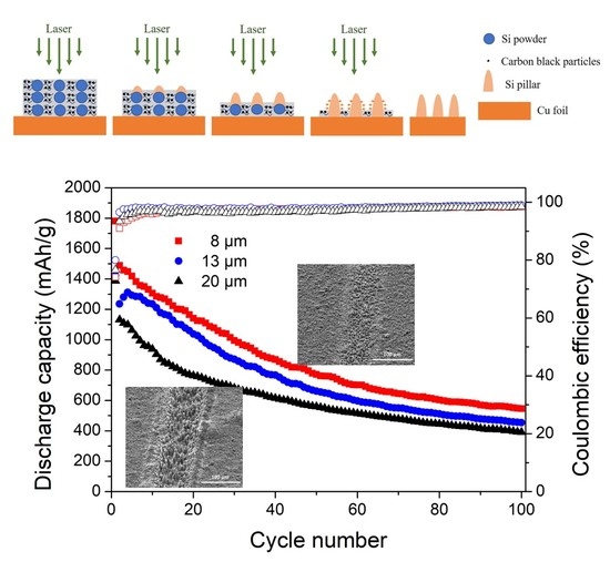
2.2. Si Micropillar Growth

The slurry layer was irradiated with an Nd:YAG laser (Megaopto Co., Ltd, Wako, Saitama, Japan) having a wavelength of 532 nm. The excitation light source was a laser diode, and the laser system was air-cooled. The laser beam had a Gaussian profile with a diameter of 85 µm. A pulse width of 48.4 ns was used at a repetition frequency of 10 kHz. According to our previous study, if the laser fluence is too high or the scan speed is too low, the pillars could be ablated due to successive laser irradiation [39]. On the other hand, if the laser fluence is too low or the scan speed too high, the Si waste powders could not be completely melted [39]. Different laser fluences and scan speeds were employed for slurry layers of different thicknesses, and the most suitable ones for each condition were chosen to be used in this study. The laser fluence was 529 mJ/cm2 for a slurry layer of 8 μm in thickness and 1057 mJ/cm2 for slurry layers of 13 and 20 μm thickness, respectively. The scan speed was 1 mm/s. Area laser irradiation was conducted on the slurry layer to fabricate Si micropillar anodes for electrochemical testing. The line spacing was 57 µm. The laser irradiation conditions are summarized in Table 1.

2.3. Material Characterizations

The particle size of the Si waste was measured using a laser particle size analyzer (LA-960, Horiba, Ltd., Kyoto, Japan). The composition of the Si waste was analyzed with an X-ray diffractometer (D8 Advance, Bruker, Billerica, MA, USA) using Cu Kα radiation at 40 kV and 40 mA. The X-ray diffraction (XRD) results were collected from 10° < 2θ < 100° at a scan rate of 2°/min. A scanning electron microscope (SEM, Model Inspect S50, FEI, OR, USA) was used to examine the surface morphology of Si micropillars. Quantitative measurement of the average base diameter of micropillars was performed using ImageJ software (National Institutes of Health, USA). Elemental analysis of the Si anode after 100 cycles was carried out using energy-dispersive X-ray (EDX) equipped with this SEM.

2.4. Electrochemical Measurements

An electrochemical cell (HS flat cell) was assembled by sandwiching a polypropylene membrane separator (Selion P2010, CS Tech Co., Ltd., Wonju, South Korea) between a lithium metal foil and a Si micropillar anode. LiPF6 (1.0 M) in a mixture of ethylene carbonate and diethyl carbonate (1:1 vol %) was used as the liquid electrolyte (Hohsen Corp., Osaka, Japan). All electrochemical cells were assembled in an argon-filled glove box (DBO-1KP-K02, Miwa MFG). Galvanostatic cycling tests were carried out on a charge/discharge test system (HJ-1001 SM8, Hokuto Denko Corp., Tokyo, Japan) at varying current rates at room temperature. The discharge and charge cycle refer to the lithiation and delithiation of the anode, respectively. The voltage cutoffs were 0.01 and 1.5 V vs. Li/Li+. The mass loadings of Si were 2.48 mg/cm2 for 20 μm layer thickness, 1.78 mg/cm2 for 13 μm layer thickness, and 1.18 mg/cm2 for 8 μm layer thickness, respectively. The current density of 1C rate used in this research was 3579 mA/g. After electrochemical testing, the electrochemical cells were disassembled in a glove box. The Si micropillar anodes were rinsed with dimethyl carbonate (DMC) solvent five times to remove the residual electrolyte.

3. Results and Discussion

3.1. Si Micropillar Growth

Figure 1 shows the SEM image, particle size distribution, and XRD pattern of as-received Si powders. It can be seen that the as-received Si powders had an inherently irregular morphology, with the size having a wide range from a few sub-microns to over 10 microns. As illustrated in Figure 1c, the strong X-ray diffraction peaks of the as-received waste powder were all indexed to crystal planes of silicon and no other phases were observed. In addition, since Cu Kα1 (λ = 1.5406 Å) and Cu Kα2 (λ = 1.54443 Å) radiation were both involved, the diffraction peaks were split at high angles.
Figure 2a–c show SEM images of Si micropillars growing from 8-, 13-, and 20-µm-thick slurry layers by single-line laser irradiations. Arrays of micropillars were formed along the laser irradiation path. It can be observed that the micropillars from the 20-µm-thick slurry layer were the largest (Figure 2c). With the decrease in slurry layer thickness, the micropillars became smaller and were distributed more densely (Figure 2a,b). The average base diameters of micropillars were measured and presented in Figure 2d. The diameter of micropillars growing from the 20-µm-thick slurry layer was the largest, with a value of 8 µm. By decreasing the slurry layer thickness to 13 µm, the diameter of the resultant micropillars was reduced to 6 µm. The smallest base diameter (~4 µm) was obtained from the thinnest slurry layer (8 µm), which was only half that from the 20-µm-thick slurry layer.
The mechanism of Si micropillar growth from slurry layers of different thicknesses during the laser irradiation process is illustrated in Figure 3. As clarified by our previous research [39], Si particles on the top layers were directly heated by the laser and melted onto the Si particles under them. Due to the thermal conduction, with further laser heating, all the Si particles completely melted and spread out onto the Cu foil. In order to achieve stable equilibrium with low surface energy, the liquid Si merged to form larger Si islands on the Cu foil. During this process, carbon black, as a sacrificial agent, underwent plasma gasification and partial ignition in the air, generating a high-pressure plasma and carbon oxide gas around the Si islands. Owing to the plasma-induced pressure around the Si islands, they were stretched along the laser beam direction and eventually micropillars were formed after solidification. In the course of this process, two scenarios were considered. If the slurry layer was thin, small Si islands formed, leading to small and thin pillars (Figure 3a). On the other hand, if a thick slurry layer was applied, the Si islands were relatively large since more particles were melted from the top layers and accumulated on the Cu foil. Therefore, larger micropillars were obtained (Figure 3b). This study demonstrates the possibility of generating extremely small Si pillars on Cu foils by laser irradiation of a very thin layer of waste Si slurry. If the pillar was thin enough, the situation may approach that of Si NWs.

3.2. Electrochemical Performance

The rate performances of Si micropillars at a series of increased current rates of 0.1, 0.2, 0.5, and 1.0 C are presented in Figure 4a. The coulombic efficiencies in the initial cycle are 79.9, 79.4, and 75.7% for Si pillars growing from 8-, 13-, and 20-µm-thick slurry layers, respectively. They all increase to over 97% in the subsequent cycles. The coulombic efficiency in the first cycle was naturally poor because the high surface-area-to-volume ratio caused more Li+ to be trapped in the SEI layer [44]. It should be noted that the coulombic efficiency shows at slightly over 100% in cycle 26. The reason for this is likely to be that, in cycle 25 with a 1.0 C rate, the delithiation is not complete; some Li ions still remain in the anode. This causes the delithiation in cycle 26 to be a little higher than the lithiation, and therefore the coulombic efficiency is over 100%. The Si micropillars from 20-µm-thick slurry layer exhibited the worst performance with a capacity of 1378 mAh/g at 0.1 C and 303 mAh/g at 1.0 C, respectively. As the slurry layer thickness decreased to 13 µm, the specific capacity of micropillars increased to 1463 mAh/g at 0.1 C and 548 mAh/g at 1.0 C, respectively. The capacity was further improved when the slurry layer became much thinner. The highest capacity of 1647 mAh/g at 0.1 C was obtained for the thinnest slurry layer (8 µm), with a capacity of 582 mAh/g at 1.0 C that was almost doubled compared with that of the 20-µm-thick slurry layer. Figure 4b compares the cycling performances of Si micropillars at a current rate of 0.1 C. Significant differences in discharge capacity can be observed at the early period of cycling among the three samples. Si micropillars from the thinnest slurry layer (8 µm) present the best electrochemical performance with an initial discharge capacity of 1780 mAh/g, followed by the 13-µm-thick slurry layer with an initial discharge capacity of 1423 mAh/g. When the thickness of the slurry layer increased to 20 µm, the initial discharge capacity dropped to 1387 mAh/g. However, the subsequent capacity decay was rapid; it dropped down to nearly half of the initial discharge capacity at the 50th cycle for all the three samples. The discrepancy in discharge capacity became smaller as the cycle number increased. After 60 cycles, the discharge capacities of all three samples were very close to each other. The reversible capacities over 100 cycles of 8, 13, and 20 µm slurry layers were approximately 545, 453, and 385 mAh/g, respectively.
The enhanced electrochemical performance of Si micropillars at the early period of cycling has been achieved by reducing the slurry layer thickness. Such improvement can be attributed to the following reasons:
(1)
Smaller micropillars had a higher surface-area-to-volume ratio, which could reduce the occurrence of cracks on the surface and maintain the mechanical integrity.
(2)
Increased surface area and denser distribution of smaller micropillars provided more contact area between electrolyte and Si for large Li+ flux.
(3)
Shorter Li+ diffusion pathway in micropillars with a smaller diameter, which ensured a fast and homogeneous lithiation [35].
It is well known that the high conductivity of the active material and short path length of ions are two important factors that improve the rate performance of electrode for Li-ion batteries [45]. The characteristic time constant t for ion diffusion is proportional to the square of the diffusion length L and inversely proportional to ion diffusivity (D) [22,46], as shown in Equation (1). The reduction in the diameter of Si micropillars (equivalent to diffusion length L) is an effective way to shorten the diffusion time t, and therefore improve the electrochemical properties of electrode material.
tL2/D

3.3. Morphological Change of Si Micropillars during Electrochemical Cycling

To clarify the reasons for the rapid capacity decay in the early stage and the insignificant discrepancy in the capacities of three samples at the later period of cycling, as shown in Figure 4b, the morphological change of Si micropillars during electrochemical cycling was further examined. Micropillars growing from the 13-µm-thick slurry layer were used to study the morphological change during electrochemical cycling. The anode surface was characterized using SEM in terms of top view (Figure 5a), 45° tilted view (Figure 5b), and side view (Figure 5c) after 1, 5, 35, and 100 cycles, respectively. After give cycles, the individual pillar structure could be observed, suggesting that volume expansion of Si had not occurred significantly. SEI products may form on the surface of micropillars due to the reductive reaction of electrodes and electrolytes [47]. After 35 cycles, the pillar structure turned into a separate island-like structure of irregular shapes. This may be because Si micropillars expanded during the charge/discharge process, and adjacent pillars aggregated to form islands with irregular shapes [48]. After 100 cycles, the spaces between the islands were further reduced, and the anode surface became flat. Some cracks can be seen on the anode surface, which could be associated with the contraction of Si in the delithiation process. The similar surface morphology of Si nanowire electrodes after 100 cycles was reported by Laik et al. [49]. It should be pointed out that, even though there were cracks on the anode surface, the Si layer was attached firmly to the Cu foil after 100 cycles, as seen from Figure 5c. The strong bond between the Si pillars and Cu foil could be due to two aspects: one is the remaining electrically conductive binder existing between them, and the other is the direct interfacial diffusion occurring between Si and Cu at a high temperature [50]. This demonstrates that the pillar structure significantly absorbed the volume expansion like the Si NW structure and prevented the destructive delamination of the Si layer from the Cu foil, which had been a serious problem for Si NP anodes.
Figure 5d compares the thickness of the Si layer on the Cu foil after a varying number of cycles. It can be seen that the volume expansion was negligible in the first cycle and the Si layer thickness remained about 8 µm. The thickness of the Si layer increased slightly to 11 µm after five cycles. However, a huge growth in Si layer thickness to about 30 µm can be observed after 100 cycles. This means that the Si layer thickness increased by a factor of four compared with the pristine anode sample. The volume expansion of Si could be one of the causes of this change. Another cause could be the continuous formation of SEI products. According to the study of SEI growth on Si nanocones by Li et al. [47], the SEI should have grown on the surface of micropillars continuously. After filling the space among the micropillars, SEI would further form and grow on the top layer of the micropillars. The thickness of the extra SEI layer on top of the micropillars could be several micrometers after dozens of cycles [47].
The EDX spectrum of a Si micropillar anode after 100 cycles and the mapping analysis of the detected elements are shown in Figure 6. The detected elements are O, C, Si, F, and P. The presence of O, C, Si, and F is consistent with the possible SEI products such as Li2CO3, (CH2OCO2Li)2, and LiF [51]. The high amount of O is likely due to the oxidation of anode when it was transferred from the glove box to the SEM chamber for characterization. The detection of only a small amount of P (1.37 wt %) indicates that only a tiny amount of electrolyte residue is left on the Si anode. Since Li has very low energy of characteristic radiation, it cannot be detected in the EDX spectrum. The EDX result evidences that an SEI layer has formed on the top layer of the silicon anode after 100 cycles.
A schematic model (Figure 7) is used to illustrate the morphological change of Si micropillars during electrochemical cycling. Si micropillars expanded in the first few cycles, but the pillar structure is discernible (Figure 7b,c). SEI layers formed on the surfaces of micropillars due to the high surface area. However, owing to limited space among micropillars, they merged with each other and formed an island-like structure (Figure 7d). After long-term cycling, an additional SEI layer formed on the top of the anode, and the anode became a flat and thick film with microsized cracks (Figure 7e). The accumulation of SEI products in the space among the micropillars as well as on the top layer of micropillars participates in the capacity decay by obstructing Li+ from accessing the Si.
Finally, the effects of waste Si slurry thickness on the electrochemical cycling performance are investigated. As shown in Figure 8, the morphologies of the anode surfaces produced from different slurry layer thicknesses became very similar after 100 cycles. The independent micropillar structure had changed into a thick film structure, regardless of the initial diameters of the micropillars. This explains the insignificant discrepancy of the capacity of micropillars with different diameters at the later period of cycling. However, by comparing Figure 8a–c, it is clear that by using a thinner Si slurry thickness to generate thinner Si micropillars, the number of surface cracks on the anode surface could be greatly reduced. The reduction of crack generation indicates a longer service life of a LIB anode.

4. Conclusions

Si micropillars with various sizes were successfully fabricated from Si waste powder via nanosecond-pulsed laser irradiation for fabricating lithium-ion battery anodes. The pillar size was controllable by tuning the thickness of waste Si slurry layer. The smaller the thickness of the slurry layer, the smaller the size of the Si micropillars. The rate capability and capacity were dependent on the pillar size: the smaller the pillars, the better the electrochemical properties. The morphological changes of Si micropillars during the charge/discharge process caused the capacity decay in the later period of cycling. During the electrochemical cycling, Si micropillars expanded and formed an island-like structure. After 100 cycles, the Si layer was a flat and thick film with microsized cracks. The number of cracks could be reduced greatly by using a thinner Si slurry layer for micropillar generation. However, even though there was crack generation on the anode surface, the Si layer was firmly attached to the Cu foil after 100 cycles, which strongly demonstrated that the pillar structure had significantly absorbed the volume expansion and prevented the destructive delamination of the Si layer from the Cu foil.
This study has demonstrated the possibility of an efficient and environmentally friendly method of fabricating Si-based LIB anodes from waste Si materials. Future research will be focused on improving the cycling performance in the later period by optimizing the Si micropillar generation and controlling SEI formation.

Author Contributions

X.Y. and J.Y. designed the experiments. X.Y. and N.T. performed and analyzed the experiments. X.Y., Y.K., L.L. and J.Y. wrote the manuscript. J.Y. supervised the project.

Funding

This study has been financially supported by the Japan Society for the Promotion of Science, Grant-in-Aid for Exploratory Research, 17K18833 (2017–2019), and the Leverhulme Trust (UK), Grant Reference Number VP1-2018-022.

Conflicts of Interest

The authors declare no conflict of interest.

References

  1. Kinoshita, K.; Zaghib, K. Negative electrodes for Li-ion batteries. J. Power Source 2002, 110, 416–423. [Google Scholar] [CrossRef] [Green Version]
  2. Dunn, B.; Kamath, H.; Tarascon, J.-M. Electrical energy storage for the grid: A battery of choices. Science 2011, 334, 928–935. [Google Scholar] [CrossRef] [PubMed]
  3. Armand, M.; Tarascon, J.-M. Building better batteries. Nature 2008, 451, 652. [Google Scholar] [CrossRef] [PubMed]
  4. Maddipatla, R.; Loka, C.; Choi, W.; Lee, K.-S. Nanocomposite of Si/C Anode Material Prepared by Hybrid Process of High-Energy Mechanical Milling and Carbonization for Li-Ion Secondary Batteries. Appl. Sci. 2018, 8, 2140. [Google Scholar] [CrossRef]
  5. Lu, G.; Qiu, S.; Lv, H.; Fu, Y.; Liu, J.; Li, X.; Bai, Y.-J. Li-ion storage performance of MnO nanoparticles coated with nitrogen-doped carbon derived from different carbon sources. Electrochim. Acta 2014, 146, 249–256. [Google Scholar] [CrossRef]
  6. Lv, H.; Qiu, S.; Lu, G.; Fu, Y.; Li, X.; Hu, C.; Liu, J. Nanostructured antimony/carbon composite fibers as anode material for lithium-ion battery. Electrochim. Acta 2015, 151, 214–221. [Google Scholar] [CrossRef]
  7. De Sutter, L.; Berckmans, G.; Marinaro, M.; Smekens, J.; Firouz, Y.; Wohlfahrt-Mehrens, M.; van Mierlo, J.; Omar, N. Comprehensive Aging Analysis of Volumetric Constrained Lithium-Ion Pouch Cells with High Concentration Silicon-Alloy Anodes. Energies 2018, 11, 2948. [Google Scholar] [CrossRef]
  8. Choi, J.W.; Aurbach, D. Promise and reality of post-lithium-ion batteries with high energy densities. Nat. Rev. Mater. 2016, 1, 16013. [Google Scholar] [CrossRef]
  9. Casimir, A.; Zhang, H.; Ogoke, O.; Amine, J.C.; Lu, J.; Wu, G. Silicon-based anodes for lithium-ion batteries: Effectiveness of materials synthesis and electrode preparation. Nano Energy 2016, 27, 359–376. [Google Scholar] [CrossRef] [Green Version]
  10. Li, X.; Gu, H.; Liu, J.; Wei, H.; Qiu, S.; Fu, Y.; Lv, H.; Lu, G.; Wang, Y.; Guo, Z. Multi-walled carbon nanotubes composited with nanomagnetite for anodes in lithium ion batteries. RSC Adv. 2015, 5, 7237–7244. [Google Scholar] [CrossRef]
  11. Fu, Y.; Gu, H.; Yan, X.; Liu, J.; Wang, Y.; Huang, J.; Li, X.; Lv, H.; Wang, X.; Guo, J. Chromium (III) oxide carbon nanocomposites lithium-ion battery anodes with enhanced energy conversion performance. Chem. Eng. J. 2015, 277, 186–193. [Google Scholar] [CrossRef]
  12. Qiu, S.; Lu, G.; Liu, J.; Lyu, H.; Hu, C.; Li, B.; Yan, X.; Guo, J.; Guo, Z. Enhanced electrochemical performances of MoO 2 nanoparticles composited with carbon nanotubes for lithium-ion battery anodes. RSC Adv. 2015, 5, 87286–87294. [Google Scholar] [CrossRef]
  13. Lyu, H.; Liu, J.; Qiu, S.; Cao, Y.; Hu, C.; Guo, S.; Guo, Z. Carbon composite spun fibers with in situ formed multicomponent nanoparticles for a lithium-ion battery anode with enhanced performance. J. Mater. Chem. A 2016, 4, 9881–9889. [Google Scholar] [CrossRef]
  14. Guo, S.; Lu, G.; Qiu, S.; Liu, J.; Wang, X.; He, C.; Wei, H.; Yan, X.; Guo, Z. Carbon-coated MnO microparticulate porous nanocomposites serving as anode materials with enhanced electrochemical performances. Nano Energy 2014, 9, 41–49. [Google Scholar] [CrossRef]
  15. Obrovac, M.N.; Christensen, L. Structural Changes in Silicon Anodes during Lithium Insertion/Extraction. Electrochem. Solid State Lett. 2004, 7, A93–A96. [Google Scholar] [CrossRef]
  16. Zhou, X.; Cao, A.-M.; Wan, L.-J.; Guo, Y.-G. Spin-coated silicon nanoparticle/graphene electrode as a binder-free anode for high-performance lithium-ion batteries. Nano Res. 2012, 5, 845–853. [Google Scholar] [CrossRef]
  17. Wu, H.; Cui, Y. Designing nanostructured Si anodes for high energy lithium ion batteries. Nano Today 2012, 7, 414–429. [Google Scholar] [CrossRef]
  18. Bai, Z.; Tu, W.; Zhu, J.; Li, J.; Deng, Z.; Li, D.; Tang, H. POSS-Derived Synthesis and Full Life Structural Analysis of Si@ C as Anode Material in Lithium Ion Battery. Polymers 2019, 11, 576. [Google Scholar] [CrossRef] [PubMed]
  19. Key, B.; Bhattacharyya, R.; Morcrette, M.; Seznec, V.; Tarascon, J.-M.; Grey, C.P. Real-time NMR investigations of structural changes in silicon electrodes for lithium-ion batteries. J. Am. Chem. Soc. 2009, 131, 9239–9249. [Google Scholar] [CrossRef] [PubMed]
  20. McDowell, M.T.; Lee, S.W.; Nix, W.D.; Cui, Y. 25th anniversary article: Understanding the lithiation of silicon and other alloying anodes for lithium-ion batteries. Adv. Mater. 2013, 25, 4966–4985. [Google Scholar] [CrossRef] [PubMed]
  21. Boukamp, B.; Lesh, G.; Huggins, R. All-solid lithium electrodes with mixed-conductor matrix. J. Electrochem. Soc. 1981, 128, 725–729. [Google Scholar] [CrossRef]
  22. Bruce, P.G.; Scrosati, B.; Tarascon, J.M. Nanomaterials for rechargeable lithium batteries. Angew. Chem. Int. Ed. Engl. 2008, 47, 2930–2946. [Google Scholar] [CrossRef] [PubMed]
  23. Zhu, B.; Jin, Y.; Tan, Y.; Zong, L.; Hu, Y.; Chen, L.; Chen, Y.; Zhang, Q.; Zhu, J. Scalable Production of Si Nanoparticles Directly from Low Grade Sources for Lithium-Ion Battery Anode. Nano. Lett. 2015, 15, 5750–5754. [Google Scholar] [CrossRef]
  24. Liu, X.H.; Zhong, L.; Huang, S.; Mao, S.X.; Zhu, T.; Y, J. Huang, Size-dependent fracture of silicon nanoparticles during lithiation. ACS Nano 2012, 6, 1522–1531. [Google Scholar] [CrossRef] [PubMed]
  25. Choi, N.-S.; Yao, Y.; Cui, Y.; Cho, J. One dimensional Si/Sn-based nanowires and nanotubes for lithium-ion energy storage materials. J. Mater. Chem. 2011, 21, 9825–9840. [Google Scholar] [CrossRef]
  26. Ryu, J.H.; Kim, J.W.; Sung, Y.-E.; M, S. Oh, Failure modes of silicon powder negative electrode in lithium secondary batteries. Electrochem. Solid State Lett. 2004, 7, A306–A309. [Google Scholar] [CrossRef]
  27. Chan, C.K.; Ruffo, R.; Hong, S.S.; Cui, Y. Surface chemistry and morphology of the solid electrolyte interphase on silicon nanowire lithium-ion battery anodes. J. Power Source 2009, 189, 1132–1140. [Google Scholar] [CrossRef]
  28. Chan, C.K.; Peng, H.; Liu, G.; McIlwrath, K.; Zhang, X.F.; Huggins, R.A.; Cui, Y. High-performance lithium battery anodes using silicon nanowires. Nat. Nanotechnol. 2008, 3, 31–35. [Google Scholar] [CrossRef]
  29. Wu, H.; Chan, G.; Choi, J.W.; Ryu, I.; Yao, Y.; McDowell, M.T.; Lee, S.W.; Jackson, A.; Yang, Y.; Hu, L.; et al. Stable cycling of double-walled silicon nanotube battery anodes through solid-electrolyte interphase control. Nat. Nanotechnol. 2012, 7, 310–315. [Google Scholar] [CrossRef]
  30. Chockla, A.M.; Harris, J.T.; Akhavan, V.A.; Bogart, T.D.; Holmberg, V.C.; Steinhagen, C.; Mullins, C.B.; Stevenson, K.J.; A, B. Korgel, Silicon nanowire fabric as a lithium ion battery electrode material. J. Am. Chem. Soc. 2011, 133, 20914–20921. [Google Scholar] [CrossRef]
  31. Chan, C.K.; Patel, R.N.; O’Connell, M.J.; Korgel, B.A.; Cui, Y. Solution-grown silicon nanowires for lithium-ion battery anodes. ACS Nano 2010, 4, 1443–1450. [Google Scholar] [CrossRef] [PubMed]
  32. Ruffo, R.; Hong, S.S.; Chan, C.K.; Huggins, R.A.; Cui, Y. Impedance analysis of silicon nanowire lithium ion battery anodes. J. Phys. Chem. C 2009, 113, 11390–11398. [Google Scholar] [CrossRef]
  33. Park, M.H.; Kim, M.G.; Joo, J.; Kim, K.; Kim, J.; Ahn, S.; Cui, Y.; Cho, J. Silicon nanotube battery anodes. Nano Lett. 2009, 9, 3844–3847. [Google Scholar] [CrossRef] [PubMed]
  34. Song, T.; Hu, L.; Paik, U. One-Dimensional Silicon Nanostructures for Li Ion Batteries. J. Phys. Chem. Lett. 2014, 5, 720–731. [Google Scholar] [CrossRef] [PubMed]
  35. Gohier, A.; Laïk, B.; Pereira-Ramos, J.-P.; Cojocaru, C.S.; Tran-Van, P. Influence of the diameter distribution on the rate capability of silicon nanowires for lithium-ion batteries. J. Power Source 2012, 203, 135–139. [Google Scholar] [CrossRef] [Green Version]
  36. Choi, M.; Kim, J.C.; Kim, D.W. Waste Windshield-Derived Silicon/Carbon Nanocomposites as High-Performance Lithium-Ion Battery Anodes. Sci. Rep. 2018, 8, 960. [Google Scholar] [CrossRef] [PubMed]
  37. Iwabuchi, Y.; Yan, J. Laser sintering of silicon powder and carbon nanofibers for porous composite thick films. Appl. Phys. Expr. 2015, 8, 026501. [Google Scholar] [CrossRef]
  38. Yan, J.; Okada, K. Fabrication of silicon-based porous nanocomposite films by focused infrared light sintering. CIRP Ann. 2016, 65, 217–220. [Google Scholar] [CrossRef]
  39. Yan, J.; Noguchi, J.; Terashi, Y. Fabrication of single-crystal silicon micro pillars on copper foils by nanosecond pulsed laser irradiation. CIRP Ann. 2017, 66, 253–256. [Google Scholar] [CrossRef]
  40. Matsumoto, T.; Kimura, K.; Nishihara, H.; Kasukabe, T.; Kyotani, T.; Kobayashi, H. Fabrication of Si nanopowder from Si swarf and application to high-capacity and low cost Li-ion batteries. J. Alloys Compd. 2017, 720, 529–540. [Google Scholar] [CrossRef]
  41. Jang, H.D.; Kim, H.; Chang, H.; Kim, J.; Roh, K.M.; Choi, J.H.; Cho, B.G.; Park, E.; Kim, H.; Luo, J.; et al. Aerosol-assisted extraction of silicon nanoparticles from wafer slicing waste for lithium ion batteries. Sci. Rep. 2015, 5, 9431. [Google Scholar] [CrossRef] [PubMed]
  42. Bao, Q.; Huang, Y.-H.; Lan, C.-K.; Chen, B.-H.; Duh, J.-G. Scalable Upcycling Silicon from Waste Slicing Sludge for High-performance Lithium-ion Battery Anodes. Electrochim. Acta 2015, 173, 82–90. [Google Scholar] [CrossRef]
  43. Gauthier, M.; Mazouzi, D.; Reyter, D.; Lestriez, B.; Moreau, P.; Guyomard, D.; Roué, L. A low-cost and high performance ball-milled Si-based negative electrode for high-energy Li-ion batteries. Energy Environ. Sci. 2013, 6, 2145–2155. [Google Scholar] [CrossRef]
  44. Jin, Y.; Zhu, B.; Lu, Z.; Liu, N.; Zhu, J. Challenges and Recent Progress in the Development of Si Anodes for Lithium-Ion Battery. Adv. Energy Mater. 2017, 7, 1700715. [Google Scholar] [CrossRef]
  45. Tang, Y.; Zhang, Y.; Deng, J.; Qi, D.; Leow, W.R.; Wei, J.; Yin, S.; Dong, Z.; Yazami, R.; Chen, Z. Unravelling the Correlation between the Aspect Ratio of Nanotubular Structures and Their Electrochemical Performance To Achieve High-Rate and Long-Life Lithium-Ion Batteries. Angew. Chem. 2014, 126, 13706–13710. [Google Scholar] [CrossRef]
  46. Arico, A.S.; Bruce, P.; Scrosati, B.; Tarascon, J.-M.; van Schalkwijk, W. Nanostructured Materials for Advanced Energy Conversion and Storage Devices. Nat. Mater. 2005, 4, 366–377. [Google Scholar]
  47. Luo, F.; Chu, G.; Xia, X.; Liu, B.; Zheng, J.; Li, J.; Li, H.; Gu, C.; Chen, L. Thick solid electrolyte interphases grown on silicon nanocone anodes during slow cycling and their negative effects on the performance of Li-ion batteries. Nanoscale 2015, 7, 7651–7658. [Google Scholar] [CrossRef] [PubMed]
  48. Lee, S.W.; McDowell, M.T.; Choi, J.W.; Cui, Y. Anomalous shape changes of silicon nanopillars by electrochemical lithiation. Nano Lett. 2011, 11, 3034–3039. [Google Scholar] [CrossRef]
  49. Leveau, L.; Laïk, B.; Pereira-Ramos, J.-P.; Gohier, A.; Tran-Van, P.; Cojocaru, C.-S. Silicon nano-trees as high areal capacity anodes for lithium-ion batteries. J. Power Source 2016, 316, 1–7. [Google Scholar] [CrossRef]
  50. Corn, S.H.; Falconer, J.L.; Czanderna, A. The copper–silicon interface: Composition and interdiffusion. J. Vac. Sci. Technol. A Vac. Surf. Films 1988, 6, 1012–1016. [Google Scholar] [CrossRef]
  51. Etacheri, V.; Haik, O.; Goffer, Y.; Roberts, G.A.; Stefan, I.C.; Fasching, R.; Aurbach, D. Effect of fluoroethylene carbonate (FEC) on the performance and surface chemistry of Si-nanowire Li-ion battery anodes. Langmuir 2011, 28, 965–976. [Google Scholar] [CrossRef] [PubMed]
Figure 1. (a) SEM image, (b) particle size distribution, and (c) X-ray diffraction pattern of as-received Si waste powders.
Applsci 09 03623 g001
Figure 2. SEM images of Si micropillars growing from slurry layers with thicknesses of (a) 8, (b) 13 and (c) 20 µm. (d) Base diameters of micropillars growing from various slurry layer thicknesses.
Applsci 09 03623 g002
Figure 3. Schematic drawing of the laser irradiation process on (a) a thin slurry layer and (b) a thick slurry layer.
Applsci 09 03623 g003
Figure 4. (a) Rate capabilities of Si micropillars measured at the varying current rates. (b) Discharge capacities of Si micropillars and corresponding coulombic efficiencies as a function of cycle number.
Applsci 09 03623 g004
Figure 5. SEM images of Si micropillars after a varying number of cycles from (a) top view; (b) 45° tilted view; (c) side view. (d) Thickness of Si anode measured from (c).
Applsci 09 03623 g005aApplsci 09 03623 g005b
Figure 6. (a) EDX spectrum of Si anode after 100 cycles; (b) EDX maps of O, C, Si, F, and P on the Si anode.
Applsci 09 03623 g006
Figure 7. Schematic of morphological change of Si micropillars during the charge/discharge process: (a) initial situation, (b) pillar expansion and SEI formation, (c) growth of pillar and SEI layer, (d) formation of island structure, (e) formation of thick film with cracks.
Applsci 09 03623 g007
Figure 8. Morphologies of anode surfaces after 100 cycles. Si micropillars are produced by laser irradiation on slurry layers of different thicknesses: (a,d) 8, (b,e) 13, and (c,f) 20 µm. (ac) are in low magnification. (df) are in high magnification.
Applsci 09 03623 g008
Table 1. Laser irradiation conditions.
Laser TypeNd:YAG Laser
Wavelength (nm)532
EnvironmentIn air
Beam profileGaussian
Beam diameter (μm)85
Pulse width (ns)48.4
Repetition frequency (kHz)10
Average power (mW)300, 600
Laser fluence (mJ/cm2)529, 1057
Scanning speed (mm/s)1
Line spacing for area irradiation (μm)57

