Article

Efficient Driving Plan and Validation of Aircraft NLG Emergency Extension System via Mixture of Reliability Models and Test Bench

1
School of Aeronautics, Northwestern Polytechnical University, Xi’an 710072, China
2
Department of Aeronautics and Astronautics, Fudan University, Shanghai 200433, China
*
Author to whom correspondence should be addressed.
Appl. Sci. 2019, 9(17), 3578; https://doi.org/10.3390/app9173578
Submission received: 23 July 2019 / Revised: 15 August 2019 / Accepted: 19 August 2019 / Published: 1 September 2019
(This article belongs to the Special Issue Advances in Mechanical Systems Dynamics)

Abstract

:
The emergence extension system (a mechanical system) of nose landing gear (NLG) seriously influences the reliability, safety and airworthiness of civil aircrafts. To efficiently realize the NLG emergence extension, a promising driving plan of emergence extension is proposed in respect of the reliability sensitivity analyses with a mixture of models. The working principle, fault tree analysis and four reliability models are firstly discussed for NLG emergence extension. In respect of the mixture of models, the reliability sensitivity analyses of emergence extension are then performed under different flight speeds (270 Kts, 250 Kts, 220 Kts, and 180 Kts). We find dimpling torque and aerodynamic torques of forward and after doors are the top three failure factors and the start reliability is the most in emergence extension failures. Regarding the results, feasible driving plans of NLG emergence extension are developed by adjusting the aerodynamic torque of NLG forward door, and are validated by the aerodynamic torque experiment of forward door with regard to strut rotational angle under the flight speed 270 Kts. It is indicated that (1) the adverse torque generated by the new driving mechanism obviously reduces by about 24.8% from 1462.8 N·m to 1099.6 N·m, and the transmission ratio of aerodynamic torque (force) is greatly improved when the NLG strut is lowered near to 100°; (2) under different flight speeds (180 Kts, 220 Kts, 250 Kts, and 270 Kts), the new driving mechanism realizes the lower tasks of emergence extension which cannot be completed by the initial driving mechanism; and (3) the lowering time of the new driving mechanism shortens with the increasing flight speed. The proposed new driving mechanism is verified to be reliable for emergence extension of aircraft NLG besides normal extension and to be a promising feasible driving plan with high lowering reliability. The efforts of the paper provide an efficient driving mechanism for the design of NLG in civil and military aircrafts.

1. Introduction

Landing gear is one of the key systems in aircrafts, which are used in take-off, landing and ground operation [1,2,3,4]. The landing gear of civil aircrafts includes both normal retractable system and emergency extension system. To improve the safety of aircraft landing, both Federal Aviation Regulation Part 25 (FAR 25) [5] and China Civil Aviation Regulations Part 25 (CCAR–25–R4) [6] stipulated that aircrafts must have an emergency measure to lower landing gear when its function fails normally. During the past decade, approximately 68 flight accidents happened for the related civil aircrafts such as Boeing, Airbus and other aircrafts, owing to the failure of landing gear system [7,8]. Obviously, the reliability of the retraction system seriously influences the safety of landing.
However, landing gear retraction is a sophisticated system, which further comprises many sub-systems like the mechanical, hydraulic, and control devices [9,10,11]. Hence, it is difficult to simulate the real conditions of emergency extension in engineering. Currently, the analysis of retraction system involves three categories of methods. (i) Theoretical analysis method performs the dynamic response analysis of emergency extension with a mathematical model. Owing to the complexity of both equations and ensuing calculations, the corresponding mathematical models are often simplified by compromising the accuracy of calculations. (ii) Test method acquires the accurate results approximate to the real conditions. However, this method is excessively time-consuming and costly. (iii) Simulation method accurately analyzes the integrated system of landing gear emergency extension through reasonable equivalence. The simulation analysis is generally facilitated with a co-simulation model of all the mechanical, hydraulic and control systems.
In fact, scholars have carried out a lot of works in this area. For instance, Chang et al. [12] analyzed the reliability of the steering mechanism of nose landing gear (NLG) by combining the dynamic simulation model and first-order second-moment method with an artificial neural network. Choi et al. [13] investigated the operational dynamic behaviors of a T-50 landing gear system using ADAMS and discussed the effects of temperature, aerodynamics and maneuver load on normal/emergency operation of landing gears and doors. Yin et al. [14] conducted the fault analysis of the emergency lowering of an aircraft NLG by co-simulation method and then obtained the dynamic response characteristics of the landing gear retraction system. Meanwhile, Yin et al. [15] established the dynamics model of landing gear with the limit state equation to analyze the influence of key parameters on the reliability of the retraction system. McClain et al. [16] introduced the improved landing gear system with the efforts involving the design, test and integration of components and the failure investigation. Öström et al. [17] discussed the co-simulation of two models including commercial-off-the-shelf software and low-cost flight simulation model for landing gear. Lin et al. [18] proposed the deployment and locking theory of mechanism and analyzed the reliability of a landing gear system from qualitative and quantitative perspectives, by constituting a fault tree. Zhang et al. [19] examined the dynamic performance of a landing gear system using ADAMS, during retraction (extension) operations under various flight speeds and hydraulic fluid temperatures. Chen et al. [20] presented an efficient prognostic tool based on stochastic filtering-based method, to predict the failure time of the landing gear retraction system. However, these mentioned efforts hardly involve the efficient reliability model and the sensitivity of different torques to the emergency extension of landing gear, which is significant for precisely designing the sophisticated emergency extension system of landing gear. The main reasons are that in engineering, the reliability of emergency extension is synthetically affected by start failure, continuous movement failure, movement precision failure, and static strength failure. In this case, it is urgent to develop an integrated reliability approach by considering many reliability models (i.e., starting reliability model, continuous movement reliability model, movement precision reliability model, and static strength reliability), for the comprehensive reliability sensitivity analyses of the emergency extension system.
To address this issue, this paper will systematically analyze the emergency extension fault of the NLG under the actual loading conditions. Firstly, the working principle of detailed emergency extension and failure modes are introduced. Secondly, the safety boundary equation and variables distribution of the reliability model are determined to establish the reliability models comprising starting reliability model, continuous movement reliability model, movement precision reliability model, and static strength reliability. In respect of the starting reliability model, the calculation approach of failure probability is introduced in detail under different flight speeds. Next, the sensitivity analysis of different torques to the emergency extension of landing gear is conducted to find the torques with high influence level. Finally, a promising design plan is explored to solve the problem of emergency extension fault and improve the reliability of NLG emergence extension for aircrafts, in respect of experimental validation.
The rest of the paper is organized as follows. In Section 2, the reliability models of NLG emergence extension are discussed including working principle, fault tree analysis, reliability approach, and mixture of models. The reliability sensitivity analyses of emergence extension are performed to find the failure probabilistic of emergence extension and the effect levels of bottom events in the fault tree model in Section 3. Section 4 proposes and validates efficient driving plans (driving mechanisms) by the experiment of NLG emergence extension. Conclusions and findings are summarized in Section 5.

2. Reliability Modeling of NLG EmergencyExtension

For civil aircrafts, the retraction (extension) mechanism seriously influences the safety and airworthiness of flights and the reliability of the landing gear system, which was strictly required in the relevant clauses in FAR 25 and FAR 25.729 (c) [5,6]. Therefore, it is urgent to provide the emergency measures to ensure the reliable lowering and lock of the NLG. The experiments on the effects of aerodynamic force on NLG emergency extension were conducted under four flight speeds (i.e., 270 Kts, 250 Kts, 220 Kts, and 180 Kts) during the flight-test program of an aircraft, in which Kts is the unit of flight speed. The test results show that the NLG could not lower to the designed angle degree and did not possess the reliable lowing function required. To meet the requirements of airworthiness clauses, it is necessary to address the emergency extension fault of civil aircrafts.

2.1. Working Principle of Emergency Extension

Landing gear generally consists of a retractable actuator, lock mechanism, shock absorber strut, cabin door driving mechanism, and so forth. The doors and retraction mechanism of landing gear are mechanically linked. In the case of an emergency, the emergency extension crank is rotated by the emergency extension cable mechanism to overcome the spring force of the lock and to realize the unlocking. Subsequently, under gravity and other external forces, the shock absorber strut of the landing gear is lowered to a specific position to lock the lower-lock, so that the emergency extension process is completed. In line with the function and geometrical analyses of emergency extension, the normal operation of the NLG mechanism is correlated with landing gear gravity, door gravity, aerodynamic force, damping force, unlocking force, and locking spring force. Figure 1 shows the structure diagraph of NLG emergency extension.
In respect to Figure 1, the process of emergence extension is described as follows. The landing gear is lowered and rotated around the strut rotation axis. When the landing gear is lowered, the shock absorber strut rotates around the strut rotation axis. The rocker arm 2–3 is driven by the connecting rod 1–2. The rocker arms 2–3 and 3–4 are rigid structures and move together. Then the connecting rod 5–6 isdriven by the connecting rod 4–5. The rocker arm 6–7 moves with the rocker 5–6, and the rocking arm 7–8 is carried by the connecting rod 6–7. In this time, the NLG is lowered and the forward door of the landing gear is opened. Obviously, the parts 1–2–3–4–5–6–7–8 together constitute the driving mechanism of the forward door. For the complex driving mechanism analysis of the forward door, the driving mechanism was reduced as a planar four-link mechanism [21] and spatial four-link mechanism [22] for movement reliability analyses with acceptable accuracy. The two simplifications models will be applied to the reliability of movement precision in the next work.

2.2. Fault Tree Analysis of Emergency Extension

During the process of emergency extension, it must be ensured that the NLG always rotates around the strut rotation axis. The torques of all components are induced by external loads and impact on the emergency extension. These torques are listed in Table 1.
Table 1 shows the analysis of the torque produced by the forces acting on the strut during emergency extension. The active torques produced by landing gear mass force play a leading role in the early stages of emergency extension. In the later period of emergency extension, the aerodynamic resistance torque of landing gear plays a leading role. Owing to the linkage design of the landing gear door and landing gear, the aerodynamic force of forward door and after door produces a torque during the whole process of emergency extension. The spring torque of the lock mechanism is inevitable. The spring force should ensure the safety of the lock mechanism. The retractable actuator cylinder is fixed on the airframe, because the piston rod of the retractable actuator cylinder is connected and moves with the shock absorber strut in the process of lowering and rotation. Meanwhile, the hydraulic oil rapidly flows in the actuator cylinder and return pipeline, to generate the damping torque of emergency extension, which is determined by piston speed, return pipeline length, and so on. From the above analysis, we can summarize the main reasons inducing the failure of emergency extension T as follows.
1
Excessive resistance torque on strut rotation axis (denoted by X1). The aerodynamic force of the landing gear door is too large for the driving mechanism to overcome the passive torque by the active torque of shock absorber strut, so that the landing gear cannot be lowered and locked.
2
Imprecise extension of landing gear (denoted by X2). The landing gear cannot be lowered to a predetermined position owing to the motion accuracy of the mechanism.
3
Unlocked upper-lock. The upper-lock is unlocked (denoted by X3).
4
The lower-lock is not locked (denoted by X4).
5
Static strength failure of landing gear emergency extension (denoted by X5).
In respect of the five fault reasons, the fault tree of emergency extension is established as shownin Figure 2, in which the five bottom events indicate five failure reasons in the fault tree. Obviously, the failure of one bottom event will lead to the failure of emergency extension.

2.3. Reliability Method and Mixture of Models

The reliability models of the emergency extension mechanism include the mechanism starting model, mechanism continuous movement model, mechanism movement precision model, and static strength model [23]. These reliability models can be established based on the fault tree analysis of the emergency extension mechanism and the mechanism reliability analysis theory [24]. For reliability analysis, the four reliability models actually have similar procedures. In this study, the starting reliability model is considered as a typical example to explain the reliability method. To start the mechanism from stationary to motion state, it is ensured that the driving torque M d is larger than the resistance torque M r , i.e.,
M = M d M r > 0
The starting failure probability Pf is defined as the probability that driving torque is less than resistance torque, i.e.,
P f = { M d M r < 0 }
With regard to the distribution characteristics of driving torque and resistance torque, the starting reliability index of the mechanism is expressed as
β = M ¯ d M ¯ r C d 2 M ¯ d 2 + C r 2 M ¯ r 2
where C d is the variable coefficient of driving torque; C r is the variable coefficient of resistance torque; and M ¯ d and M ¯ r denote the mean values of driving torque Md and resistance torque Mr.
In terms of the standard normal cumulative distribution function Φ(•) [25,26], the starting reliability R is
R = Φ ( β )
The starting failure probability Pf is
P f = 1 R = Φ ( β )
In this case, the first-order second-moment method is used to calculate the starting reliability. The rest of the reliability models are not repeatedly respected. The reliability model, safety boundary equation, reliability index, and parameter distributions of the bottom event [23,27,28,29] are shown in Table 2.
In terms of the above fault tree analysis, the relationship between bottom events and top events is “or” for emergency extension. All the bottom events are minimal cut sets. The occurrence probability PT of the top event is equal to the sum of the probability of occurrence for all the minimal cut-sets. In this case, the failure probability of emergency extension is
P T = i = 1 5 P ( X i )
where Xi (i = 1, 2, …, 5) is ith bottom event in the fault tree; and P(.) indicates the failure probability.
First, the failure probability of each bottom event with the reliability model is obtained by the related parameters, such as geometric sizes, material performance parameters, lowering speed, and so forth. With respect to Equation (6), the failure probability of the top event is obtained in the fault tree of emergency extension.
As for the bottom event X1 (excess passive torque), the reliability models involve starting reliability M and continuous movement reliability Mω. In the unlocking stage of emergency extension for the strut rotation angle in [0°, 2.66°], the starting reliability model is applied to compute the failure probability of the starting driving mechanism, while after unlocking (i.e., the strut rotation angle of landing gear excess 2.66°), the continuous movement reliability model is employed to evaluate the failure probability of lowering the driving mechanism. In this paper, the maximum failure probability in the whole motion process is regarded as the failure probability of the bottom event X1.

3. Reliability Sensitivity Analysis of Emergence Extension

In this section, the reliability sensitivity analyses of the NLG emergence extension system comprising reliability analysis and sensitivity analysis are investigated to provide a reference for the development and validation of a feasible plan for reducing emergence extension failure and faults.

3.1. Reliability Analysis

3.1.1. Starting Reliability Analysis of Emergency Extension

As illustrated in Table 1, the amplitudes and directions of all the forces acting on the NLG and the corresponding torque on shock absorber strut rotation axis vary during the process of emergency extension. Therefore, it is necessary to carry out force balance analysis and reliability analysis in the whole process of emergency extension. To ensure that the NLG can be lowered in an emergency, the relationship between active torques and passive torques is investigated. The above nine forces act on strut rotation axis in the form of torque. The total torque is expressed as
M T = i = 1 9 M i = M 1 + M 2 + M 3 + M 4 + M 5 + M 6 + M 7 + M 8 + M 9
Based on the starting reliability, the emergency extension is successful as MT > 0, or the emergency extension fails. Obviously, the nine torques significantly influence the normal start-up of emergency extension. When M T < 0 , the emergency extension cannot be realized. It is necessary to further analyze the relationship between torque and strut angle. Regarding the flight speed 270 Kts, the changing trend of each torque and total torque with strut rotation angle during emergency extension are shown in Figure 3.
As shown in Figure 3, (1) all the torques vary with the strut rotation angle during the emergency extension. Merely, the torque on strut rotation axis M9 stops to act on the emergence extension system after about 2.66 degrees (°) of landing gear angle, because the point at 2.66° of landing gear angle indicates that the upper-lock is unlocked to finish its mission, and its unlocking force on the emergence extension system does not exist after 2.66° of landing gear angle; (2) the torques M1 and M9 are conductive to the emergence extension in the whole process, and the torque M3 lowers the emergence extension system in [0~2.66°] and stop work after 2.66°; (3) the torques M5 and M6 provide a resistance against emergence extension, in which M5 is much larger than M6, which is very small in the whole lowering process; (4) the torques M2, M4, M7, and M8 have both a positive and negative effect on emergence extension, in which M2, M7 and M8 are firstly positive torques at 21.8°, 69.2° and 35.1°, respectively, and then negative while M4 is firstly adverse and then beneficial for emergence extension; (5) the torque of MT reaches the minimum at 2.66° (unlocking completion stage) and 100.1° (ready locking stage), which indicate the two critical points inducing the failure of the emergence extension system.
By importing the nine torques and variable coefficients Ci (i = 1, 2, …, 9) with strut rotation angle into Equation (3), the starting reliability index β can be computed by
β = i = 1 9 M i i = 1 9 C i 2 M i 2
where i is the ith torque.
With respect to Equation (8), the failure probability can be obtained by the standard normal distribution function. Regarding the relevant engineering tests and empirical data [30,31,32,33], the variable coefficients of nine torques are listed in Table 3.

3.1.2. Reliability Analysisof Emergency Extension Based on Fault Tree

With regard to the reliability model, the failure probability PXi of ith bottom event Xi can be calculated quantitatively when the NLG emergency extension cannot be lowered at different flight speeds. According to engineering experiments, we find that the maximum failure of bottom event X1 occurs at [0°, 2.66°]. Therefore, we only consider the starting failure probability of the emergence extension mechanism as the failure probability of bottom event X1 in this paper. The results on the failure probability PXi under different flight speeds (270 Kts, 250 Kts, 220 Kts and 180 Kts) are shown in Table 4.
As shown in Table 4, the failure probability of the top event (emergence extension) increases with the decreasing flight speed. When the flight speed is at 180 Kts, the failure probability increases to the maximum 6.6256 × 10⁻⁵. The main reason is that the strut aerodynamic torque of landing gear and the aerodynamic torques of forward and after doorsreduce with the decline of the flight speed. In this condition, the total torque of NLG and the angular acceleration of the rotating axis drop. Therefore, when the emergency extension of NLG is put down, a large angular velocity is obtained for the rotating axis due to large flight speeds, besides smaller failure probability for emergency extension. In other words, low flight speed and angular velocity obtained against the rotating shaft will lead to larger failure probability of emergency extension.
From the above analysis, it is seen that the starting reliability is the main factor influencing the failure probability of emergency extension. Therefore, the sensitivities of the nine torques on starting reliability were discussed to determine the specific influence of torques on the start reliability of emergence extension system.

3.2. Sensitivity Analysis

To identify the main influencing factors on emergency extension fault, the sensitivity analysis is implemented under the flight speed of 270 Kts in this section.

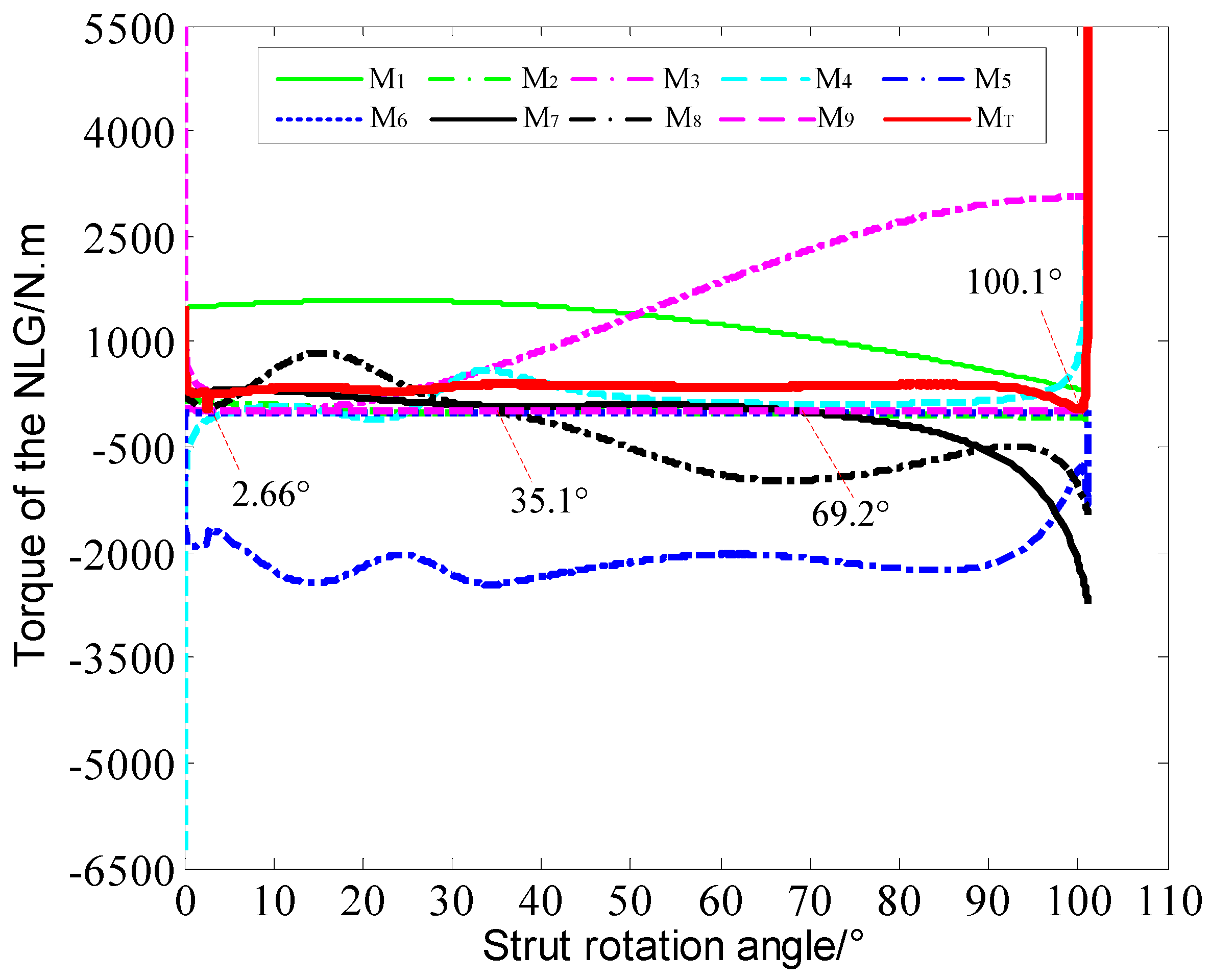
3.2.1. Sensitivity Analysis of Torques

Sensitivity is defined by the ratio of change (or gradient) of failure probability to the change of random variables. According to the reliability index of the NLG emergency extension mechanism in Equation (3) and partial derivative, the sensitivity of the ith torque is
β M i = i = 1 9 C i 2 M i 2 C i 2 M i i = 1 9 M i ( i = 1 9 C i 2 M i 2 ) 3
in which β M i reflects the influence levels of the ith torque on the failure probability of emergency extension. The larger the variation of β M i is, the larger the influence of the corresponding torque on reliability index and failure probability is.
By substituting the torque and the corresponding variable coefficient into Equation (9), the sensitivities of each torque to start reliability are obtained as shown in Figure 4. When the landing gear angle is 2.66°, the corresponding unlocking is completed, and then M9 disappears.Therefore, the sensitivity of M9 only exists in [0°, 2.66°].
As displayed in Figure 4, the sensitivities of nine torques have different change trends irregularly with strut rotation angle. Therefore, it is difficult to specifically identify which torques are the main factors influencing the failure probability of emergency extension with the variation of strut rotation angle.

3.2.2. Effect of Main Torque on Failure Probability of Emergency Extension

To determine the significant torques on the failure probability of emergency extension, ranking method is adopted to vividly order by the sensitivities of torques to the failure probability of emergency extension with the changes of strut rotation angle. The ranking is shown in Figure 5.
As revealed in Figure 5a, both the damping torque M5 and the aerodynamic torques (M7 and M8) of after and forward door are the three largest influencing the failure probability of emergency extension. When the strut rotation angle changes in [0°, 55.1759°], M5 has the largest factor affecting the failure probability of emergency extension. M8 will take the place of M5 and becomes the most influential torque when the strut rotation angle varies in [55.2889°, 79.2622°]. With the further increase of the strut rotation angle, M5 and M7 will become the most influential torques as the strut rotation angle in [79.5208°, 92.0710°] and [92.5061°, 101.1959°], respectively. Similarly, we can see the variations of the second and third torques with the strut rotation angle, as shown in Figure 5b,c. The ranking of torques is useful to guide the design of a feasible plan in emergence extension reliability improvement.

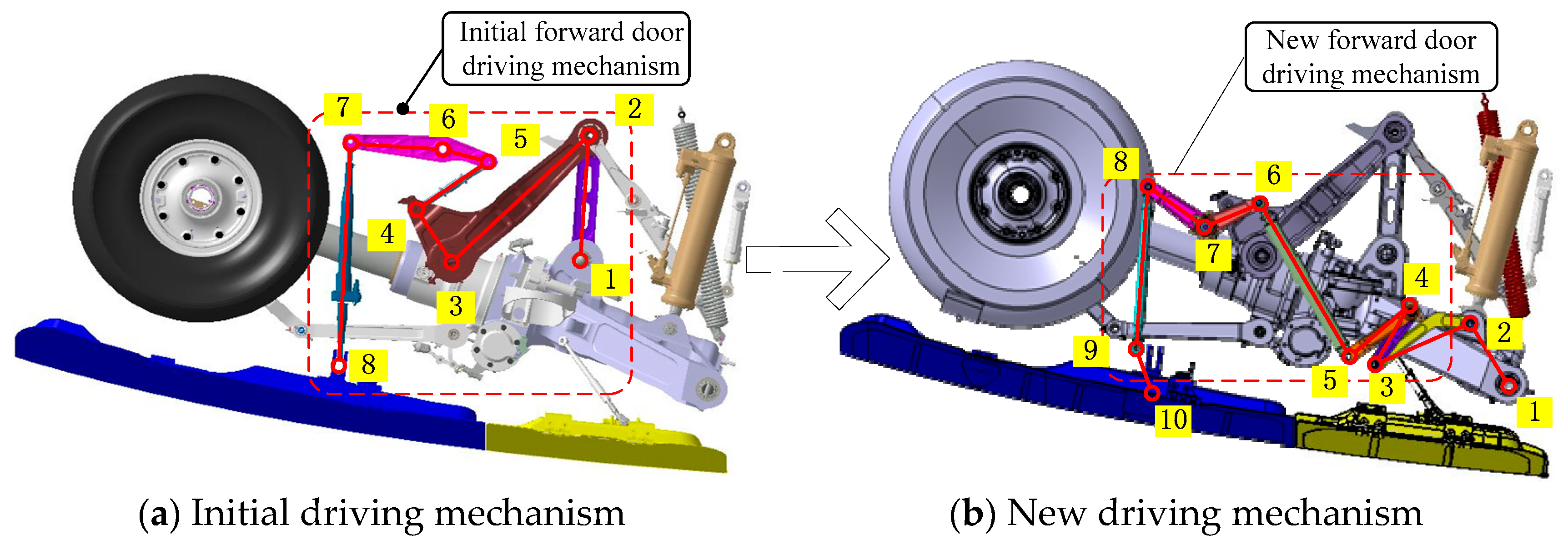
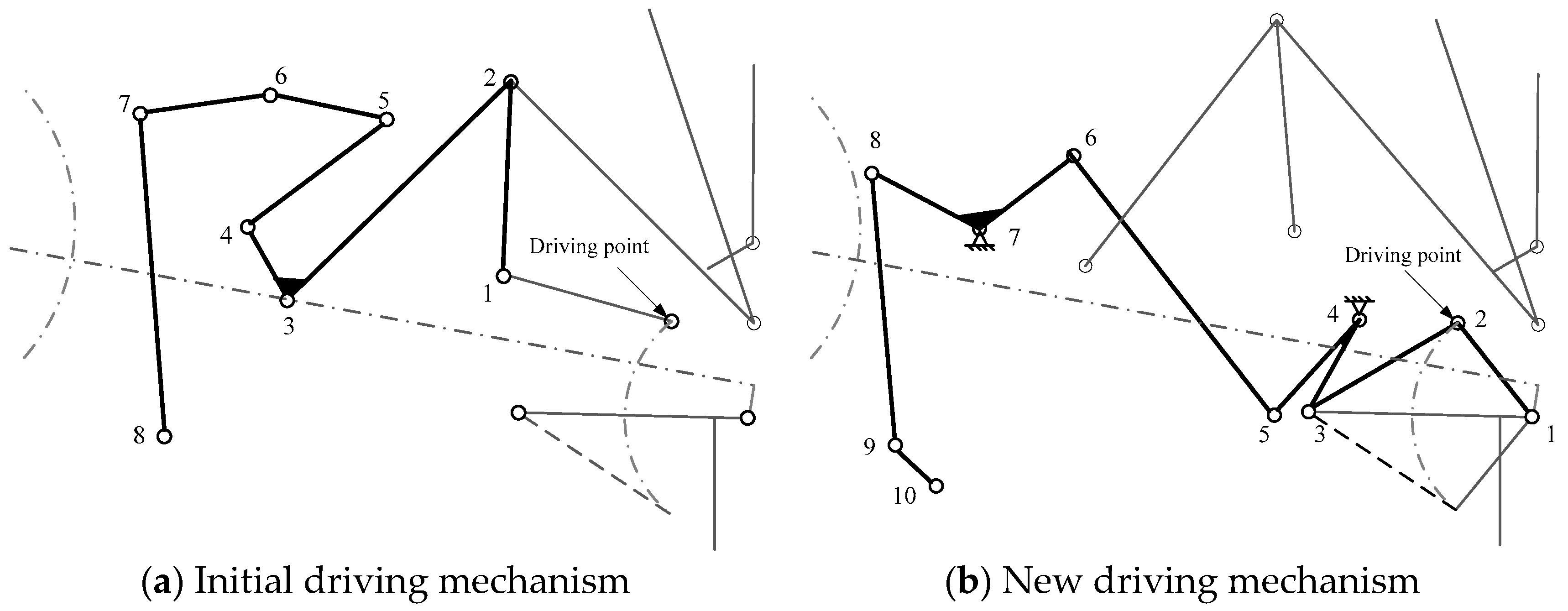
4. Proposal and Validation of New Driving Mechanism Plan

The foregoing sensitivity analyses shows that the damping torque and the aerodynamic torques of forward and after doors are the three main factors affecting the emergency extension failure. To address the engineering problem of emergence extension faults, two feasibility plans are proposed at the flight speed of 270 Kts in this paper.
Firstly, the NLG relies on kinetic energy to realize the emergency extension by reducing the damping coefficient of the actuating cylinder. Through the transient simulations of the angle variation of forward door with time under different damping coefficients of the actuating cylinder, the simulation results are drawn in Figure 6.
As demonstrated in Figure 6, (1) with the reduction of the damping coefficient, the lower NLG strut is faster, but the position at which the NLG strut finally stop remains unchanged; (2) the strut oscillates near the equilibrium position and has larger shock for smaller damping. When the damping coefficient drops below 200, the strut can be lowered and locked. In this case, however, landing gear have a larger impact on the aircraft since the lower strut only costs 3.75 s.
We verified the above simulation findings by ground tests. The test results show that it is unacceptable to break through the dead point with the assistance of the kinetic energy, by reducing the damping coefficient for the NLG. It is urgent to seek analternative plan.
Because the driving mechanism of the forward door is highly sensitive to aerodynamic force, considering the location selection and assembly requirements of the driving point of the landing gear strut, a new driving mechanism was proposed by selecting the actuating cylinder lug of landing gear as the driving point. The design principles include the below steps.
(1)
The point of intersection between the main structure and mechanism of NLG keeps invariability.
(2)
The main force-transferring path of the forward door structure is unchanged.
(3)
The mechanism has strong capacity forresisting forward door load.
The new driving mechanism of forward door is design as depicted in Figure 7.
As shown in Figure 8a, since the working principle of the emergency extension of the initial driving mechanism has been introduced in Section 2.1, we do not repeat it here. As shown in Figure 8b, the new driving mechanism of the forward door is linked to the shock absorber strut by two rocker arms and pull rods, in which the rotating axis of the rocker arm is fixed on the side plate of the landing gear door. Therefore, the switch of forward door can be driven by the shock absorber strut. When the landing gear is lowered, the shock absorber strut rotates around the strut rotation axis 1. The rocker arm 3–4 can be driven by the connecting rod 2–3. The rocker arms 3–4 and 4–5 are rigid and can move together. The rocker arm 6–7 is driven by the connecting rod 5–6. The rocker arm 7–8 moves with the rocker 6–7, and the rocking arm 9–10 is started by the effect of the connecting rod 8–9. Through the above transmission of torques from point 1 to point 10 under the driving force provided by the hydraulic system, the lowering function of NLG and the opening and closing of the landing gear forward door are realized. Obviously, the driving mechanism of the forward door consists of nine flexible manipulators (1–2, 2–3, 3–4, 4–5, 5–6, 6–7, 7–8, 8–9 and 9–10) and 10 driving pivots (1, 2, …, 10). The working principle of the emergency extension of the initial and new driving mechanism is vividly shown in Figure 8.
To validate the effectiveness and feasibility of the new design plan with the failure reason studied in Section 3, the NLG system designed by the new plan of emergence extension is tested by the iron bird test rig. The sketch map of the iron bird test system is illustrated in Figure 9 where Figure 9a is the geometric model of the iron bird test rig, and Figure 9b indicates the test system of emergence extension.
Through the experiment of the aerodynamic torque of forward door for the new emergence extension system with regard to strut rotational angle under the flight speed 270 Kts, the test results of new and initial driving mechanisms including the change curve and transmission efficiency of aerodynamic torque with strut rotation angle are drawn in Figure 10. In Figure 10, the transmission ratio ζ [34] is calculated by
ζ = T 2 T 1 = d γ d α
where T1 is the aerodynamic torqueof the landing gear forward door; T2 is the required lowering torque to overcome T1; α indicates the strut rotation angle of NLG; and γ is the rotation angle of forward door a certain state.
On the premise of limited design space and guaranteeing transmission efficiency of the mechanism, the distribution of the transmission ratio directly affects the design size, weight, and transmission life of driving mechanism. Therefore, the transmission ratiois regarded to reflect the transmission performance of the driving mechanism.
As shown in Figure 10a, the adverse torque generated by the new driving mechanism is obviously smaller than that generated by the initial driving mechanism during the emergency extension. Compared with the initial driving mechanism, the adverse torque changes from −1462.8 N·m to −1099.6 N·m and thus reduces by about 24.8%. The reduction of the negative aerodynamic torque is promising to more easily open the forward door and improve the reliability of emergence extension, which enhances the landing safety of aircrafts.
As indicated in Figure 10b, relative to the initial driving mechanism of the forward door, the transmission ratio of aerodynamic torque (force) for the new driving mechanism is greatly improved when the NLG strut is lowered near to 100°, because the transmission ratio of the new driving mechanism markedly decreases from −8.1 to −2.9 with respect of transmission ratio calculation. Therefore, the new driving mechanism can efficiently transmit the torques. The feasibility of the new design plan for emergence extension is verified again.
As seen from the above analysis, the emergency extension fault of NLG is mainly induced by unreasonable mechanism design and weak ability of withstanding aerodynamic loads. The weak ability may lead to abortively lock the landing gear for the forward door, resulting from the aerodynamic resistance of the forward door, which can be offset by the gravity and aerodynamic forces. The results show that the new mechanism has high transmission efficiency and transmission ratio although it is more complex than the initial driving mechanism. Moreover, the new driving mechanism can also slow down the closing speed of the forward door at the final stage in the lowering process of the landing gear. To support the rapidity of the new driving mechanism in opening the forward door, we tested the lowering time of the emergence extension and normal extension of aircraft NLG based on the new and initial forward door driving mechanisms, under different flight speeds simulated on the ground. The test results are listed in Table 5.
As shown in Table 5, (1) for the normal extension, the lowering time of the new driving mechanism is about 11 s under different flight speeds (180 Kts, 220 Kts, 250 Kts and 270 Kts), which is slightly longer than that of the initial driving mechanism. The reason is that the new driving mechanism with nine arms has a more complex transmission path of force and torque, than the initial driving mechanism with seven arms. However, the complexity only has a big impact on the transmission time due to small increments in lowering time; (2) for emergence extension, the new driving mechanism realized the lower tasks under different flight speeds of 180 Kts, 220 Kts, 250 Kts and 270 Kts, at which the initial driving mechanism cannot be completed. Specifically, the emergence extension of the new driving mechanism costs 17.17 s, 15.95 s, 15.24 s and 14.66 s against 180 Kts, 220 Kts, 250 Kts and 270 Kts, respectively. In addition, it is indicated that the lowering time of the new driving mechanism shortens with the increasing flight speed.
Summarily, the proposed new driving mechanism can reliably lower the emergence extension system of aircraft NLG, besides the normal extension system. The proposed new driving mechanism is illustrated to be a promising feasible driving plan with high reliability.

5. Conclusions

The purpose of this paper is to propose an efficient driving plan (i.e., new driving mechanism) of emergence extension for aircraft nose landing gear (NLG) through reliability sensitivity analyses with a mixture of models, to address the emergence extension fault of the landing gear for the initial driving mechanism. Through the reliability sensitivity analyses of the initial driving mechanism and the validation of the proposed new driving mechanism, some major conclusions and findings are summarized as follows:
1
Through the reliability analysis of emergence extension, it is illustrated that the start reliability has the most failure probability in five reliability modes (starting reliability, continuous movement reliability, movement precision reliability, and static strength reliability), indicating that the event X1 (excessive resistance torque on strut rotation axis) seriously influences the reliability of NLG emergence extension.
2
From the sensitivity analysis of NLG emergence extension, the effect levels of nine torques (M1, M2, …, M9, explained in Table 2) on the failure probability of NLG emergence extension are determined, and the sensitivity degrees of the torques M5, M8 and M7 are the top three by the order by sensitivity degree for nine torques. The conclusion is promising guidance for the driving plan design of NLG emergence extension.
3
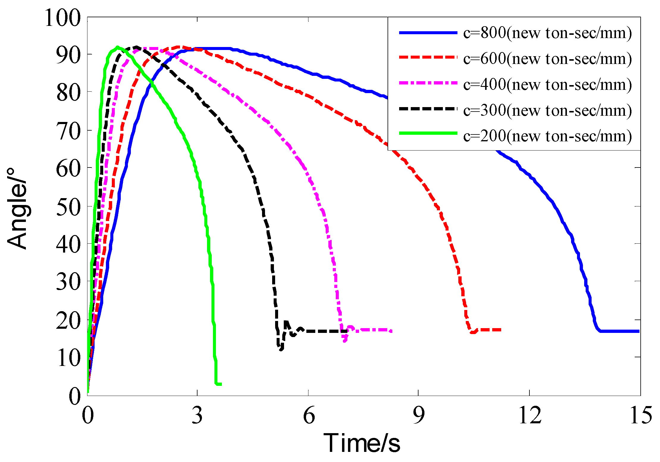
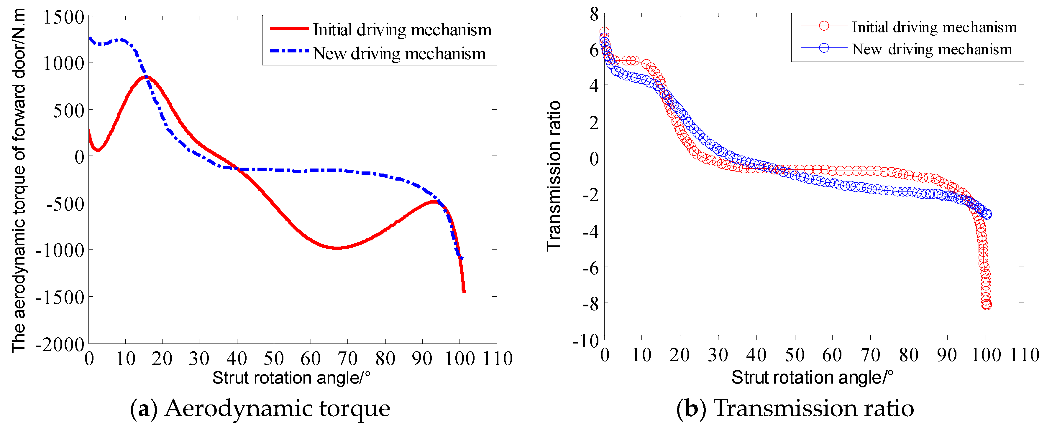
Two driving plans of NLG emergence extension are designed in this paper. One is to adjust the damping coefficients of the actuating cylinder, and the other is to the aerodynamics of forward door. Through the comparison and validation of the two plans, the second driving plan is acceptable, because this plan can reduce the adverse torque of emergence extension by about 24.8%, increase the transmission ratio of the driving mechanism, and address the emergence extension fault problem and reliably realize the emergence extension of aircraft NLG besides the normal extension system. The proposed new driving mechanism is illustrated to be a promising feasible driving plan with high reliability. The developed driving mechanism is promising in the application of civil and military aircrafts, which supports the safety and airworthiness in flight.

Author Contributions

Conceptualization, C.-W.F.; Data curation, C.L.; Formal analysis, Z.-Z.Z.; Funding acquisition, Y.-W.F.; Investigation, C.L.; Methodology, Z.-Z.Z., C.L. and C.-W.F.; Project administration, Y.-W.F.; Resources, C.-W.F.; Software, Z.-Z.Z. and C.L.; Supervision, Y.-W.F. and C.-W.F.; Writing—original draft, Z.-Z.Z.; Writing—review & editing, C.-W.F.

Funding

This research was funded by [National Natural Science Foundation of China] grant number [51875465, 51605016 and 51975124], [Special Science and Technology Program of Civil Aircraft of China] grant number [MJZ-Y-2018-92], and [Research Start-up Funding of Fudan University] grant number [FDU38341]. The APC was funded by [FDU38341].

Conflicts of Interest

The authors declare that there is no conflict of interests regarding the publication of this article.

References

  1. Krüger, W.R.; Morandini, M. Recent developments at the number simulation of landing gear dynamics. CEAS. Aeronaut. J. 2011, 1, 55–68. [Google Scholar] [CrossRef]
  2. Infante, V.; Fernandes, L.; Freitas, M.; Baptista, R. Failure analysis of a nose landing gear fork. Eng. Fail. Anal. 2017, 82, 554–565. [Google Scholar] [CrossRef]
  3. Platz, R.; Gotz, B.; Melz, T. Approach to evaluate and to compare basic structural design concepts of landing gears in early stage of development under uncertainty. Model. Validation. Uncertain. Quan. 2016, 3, 167–175. [Google Scholar]
  4. Thoai, N.; Alexandra, S.; Paul, E. Method for analyzing nose landing gear during landing using structural finite element analysis. J. Aircraft. 2012, 49, 275–280. [Google Scholar]
  5. FAR-25. Federal Aviation Regulations Part 25: Transport Category Airplanes; Federal Aviation Administration: Washington, DC, USA, 2011. [Google Scholar]
  6. CCAR-25-R4. China Civil Aviation Regulations Part 25: Transport Aircraft Airworthiness Standards; Civil Aviation Administration of China: Peking, China, 2011. [Google Scholar]
  7. Civil Aviation Safety. World Civil Aviation Accident date-base [EB/OL]. Available online: http//www.air-safety.net (accessed on 10 August 2019).
  8. Flight Safety Foundation. Aviation Safe Network [EB/OL]. Available online: aviation-safety.net (accessed on 10 August 2019).
  9. Rahmani, M.; Behdinan, K. On the effectiveness of shimmy dampers in stabilizing nose landing gears. Aerosp. Sci. Technol. 2019, 91, 272–286. [Google Scholar] [CrossRef]
  10. Knowles, J.; Krauskopf, B.; Lowenberg, M. Numerical continuation analysis of a three-dimensional aircraft main landing gear mechanism. Nonlinear Dyn. 2013, 71, 331–352. [Google Scholar] [CrossRef]
  11. Rankin, J.; Krauskopf, B.; Lowenberg, M.; Coetzee, E. Operational parameter study of aircraft dynamics on the ground. J. Comput. Nonlinear Dyn. 2010, 5, 021007. [Google Scholar] [CrossRef]
  12. Chang, Q.C.; Xue, C.J. Reliability analysis and experimental verification of landing gear steering mechanism considering environmental temperature. J. Aircraft. 2018, 53, 1154–1164. [Google Scholar] [CrossRef]
  13. Choi, S.; Kwon, H.B.; Chung, S.J.; Jung, C.R.; Sung, D.Y. An operational analysis and dynamic behavior for a landing gear system using ADAMS. J. Korean. Soc. Aeronaut. Space Sci. 2003, 31, 110–117. [Google Scholar] [Green Version]
  14. Yin, Y.; Nie, H.; Wei, X.H.; Chen, H.; Zhang, M. Fault analysis and solution of an airplane nose landing gear’s emergency lowering. J. Aircraft. 2016, 53, 1022–1032. [Google Scholar] [CrossRef]
  15. Yin, Y.; Hong, N.; Huajin, N.; Ming, Z. Reliability analysis of landing gear retraction system influenced by multifactors. J. Aircraft. 2016, 55, 713–724. [Google Scholar] [CrossRef]
  16. McClain, J.G.; Vogel, M.; Pryor, D.R.; Heyns, H.E. The United States Air Force’s landing gear systems center of excellence—A unique capability. In Proceedings of the 2007 US Air Force T&E Days, Destin, FL, USA, 13–15 February 2007. [Google Scholar]
  17. Öström, J.; Lähteenmäki, J.; Viitanen, T. F18 hornet landing simulations using ADAMS and Simulink co-Simulation. In Proceedings of the AIAA Modeling and Simulation Technologies Conference and Exhibit, Honolulu, HI, USA, 18–21 August 2008; pp. 2008–6850. [Google Scholar]
  18. Lin, Q.; Nie, H.; Ren, J.; Chen, J.B. Investigation on design and reliability analysis of a new deployable and lockable mechanism. Acta Astronaut. 2012, 73, 183–192. [Google Scholar] [CrossRef]
  19. Zhang, H.; Ning, J.; Schmelzer, O. Integrated landing gear system retraction/extension analysis using ADAMS. In Proceedings of the 2000 International ADAMS User Conference, Orlando, FL, USA, 19–21 June 2000. [Google Scholar]
  20. Chen, J.; Ma, C.B.; Song, D. Multiple failure prognosis of landing gear retraction/extension system based on H filtering. P. I. Mech. Eng. G J. Aer. 2015, 229, 1543–1555. [Google Scholar] [CrossRef]
  21. Ting, K.L.; Zhu, J.M.; Watkins, D. The effects of joint clearance on position and orientation deviation of linkages and manipulator. Mech. Mach. Theory. 2000, 35, 391–401. [Google Scholar] [CrossRef]
  22. Jhuang, C.S.; Kao, Y.Y.; Chen, D.Z. Design of one DOF closed-loop statically balanced planar linkage with link-collinear spring arrangement. Mech. Mach. Theory. 2018, 130, 301–312. [Google Scholar] [CrossRef]
  23. Song, L.K.; Fei, C.W.; Bai, G.C.; Yu, L.C. Dynamic neural network method-based improved PSO and BR algorithms for transient probabilistic analysis of flexible mechanism. Adv. Eng. Inform. 2017, 33, 144–153. [Google Scholar] [CrossRef]
  24. Lu, C.; Feng, Y.W.; Liem, R.P.; Fei, C.W. Improved kriging with extremum response surface method for structural dynamic reliability and sensitivity analyses. Aerospace Sci. Technol. 2018, 76, 164–175. [Google Scholar] [CrossRef]
  25. Zhang, C.Y.; Wei, J.S.; Jing, H.Z.; Fei, C.W. Reliability analysis of blisk low fatigue life with generalized regression extreme neural network method. Materials 2019, 12, 1545. [Google Scholar] [CrossRef] [PubMed]
  26. Lu, C.; Feng, Y.W.; Fei, C.W.; Feng, X.X.; Choy, Y.S. Weighted regression-based extremum response surface method for structural dynamic fuzzy reliability analysis. Energies. 2019, 12, 1588. [Google Scholar] [CrossRef]
  27. Liu, J.Y.; Song, B.F.; Zhang, Y.G. Competing failure model for mechanical system with multiple functional failures. Adv. Mech. Eng. 2018, 10, 1–16. [Google Scholar] [CrossRef]
  28. Zhang, J.W.; He, S.H.; Wang, D.H.; Liu, Y.P.; Yao, W.B.; Liu, X.B. A new reliability analysis model of the chegongzhuang heat-supplying tunnel structure considering the coupling of pipeline thrust and thermal effect. Materials 2018, 12, 236. [Google Scholar] [CrossRef] [PubMed]
  29. Zhao, Y.G.; Ono, T. A general procedure for first/second-order reliability method. Str. Saf. 1999, 21, 95–112. [Google Scholar] [CrossRef]
  30. He, X.; Oyadiji, O. Application of coefficient of variation in reliability-based mechanical design and manufacture. J. Mater. Process. Technol. 2001, 119, 374–378. [Google Scholar] [CrossRef]
  31. Michaael, D.; Desmond, F.; Ktrang, N. Assessment of the reliability of calculations of the coefficient of variation for normal and polymegethous human corneal endothelium. Optometry. Vision. Sci. 1993, 70, 759–770. [Google Scholar]
  32. He, X.F.; Zhai, B.; Dong, Y.M.; Liu, W.T. Safe-life analysis accounting for the loading spectra variability. Eng. Fail. Anal. 2010, 17, 1213–1220. [Google Scholar] [CrossRef]
  33. Zhang, J.H. Guidelines for Structural Strength Reliability Design of Missiles and Launch Vehicles (Metal Structural Part); China Astronautic publishing house: Beijing, China, 1994. [Google Scholar]
  34. Yao, M.Y.; Qin, D.T.; Zhou, X.Y.; Zhan, S.; Zeng, Y.P. Integrated optimal control of transmission ratio and power split ratio for a CVT-based plug-in hybrid electric vehicle. Mech. Mach. Theory 2019, 136, 52–71. [Google Scholar] [CrossRef]
Figure 1. Structure diagraph of emergency extension.
Applsci 09 03578 g001
Note: points (1,2,…, 8) indicate the connecting points between structures
Figure 2. Fault tree of emergency extension.
Applsci 09 03578 g002
Figure 3. Change of NLG torques with strut rotation angle at 270 Kts.
Applsci 09 03578 g003
Figure 4. Sensitivities degree of nine torques to strut rotation angle: (a) Sensitivity degree of M1; (b) Sensitivity degree of M2; (c) Sensitivity degree of M3; (d) Sensitivity degree of M4; (e) Sensitivity degree of M5; (f) Sensitivity degree of M6; (g) Sensitivity degree of M7; (h)Sensitivity degree of M8; (i) Sensitivity degree of M9.
Applsci 09 03578 g004
Figure 5. Influences of the top three torques on the failure probability of emergency extension under strut rotation angles: (a) the first torque number; (b) the second torque number; (c) the second torque number.
Applsci 09 03578 g005
Figure 6. Angle change of forward door under different damping coefficients.
Applsci 09 03578 g006
Figure 7. New driving mechanism and force transmission path of forward door.
Applsci 09 03578 g007
Figure 8. Working principle of initial and new driving mechanism.
Applsci 09 03578 g008
Figure 9. Sketch map of iron bird test system.
Applsci 09 03578 g009
Figure 10. Test results of initial and new driving mechanisms at 270 Kts.
Applsci 09 03578 g010
Table 1. Explanations of torques.
SymbolMeaning
M1Torque on strut rotation axis produced by the gravity of NLG
M2Torque on strut rotation axis produced by the gravity of door
M3Torque on strut rotation axis produced by the aerodynamic force of strut and wheel
M4Torque on strut rotation axis produced by the spring force of locking mechanism
M5Torque on strut rotation axis produced by damping force
M6Torque on strut rotation axis produced by friction
M7Torque on strut rotation axis produced by after-door aerodynamic force
M8Torque on strut rotation axis produced by forward-door aerodynamic force
M9Torque on strut rotation axis produced by the unlocking force of upper-lock
MTTotal torque
Table 2. Reliability model and distribution of bottom events in fault tree.
No.Bottom EventsReliability ModelsSafe Boundary EquationReliability IndexDistribution
1Excess passive torque X1Starting reliability M M = M d M r β = M ¯ d M ¯ r C d 2 M ¯ d 2 + C r 2 M ¯ r 2 Normal
Continuous movement reliability Mω M ω = ω ω β = ω ¯ ω ¯ C ω 2 ω ¯ 2 + C ω * 2 ω ¯ 2 Normal
2Imprecise lowing X2Movement precisionReliability θ0 θ 0 = θ θ * β θ = μ θ μ θ * V θ * 2 + V θ 2 Normal
3Unlocked upper-lock X3
4Failed locked lower-lock X4
5Static strength failure X5Static strengthreliability M s = S L β M = μ S μ L C S 2 μ S 2 + C L 2 μ L 2 Normal
Note: M d ¯ —the mean of driving torque Md; M r ¯ —the mean of resistance torque Mr; C d —the variable coefficient of driving torque; C r —the variable coefficient of resistance torque; ω ¯ —the mean of angular velocity ω; C ω —the variable coefficient of angular velocity; ω ¯ —the mean of allowed angular velocity ω*; C ω * 2 —the variable coefficient of velocity or angular velocity; μ θ —the mean of θ ; μ θ * —the mean of θ ; V θ —the standard deviation of θ ; V θ * —the standard deviation of θ ; μ S —the mean of mechanism static strength; μ L —the mean of mechanism load; C S —the variable coefficient of S ; C L —the variable coefficient of L .
Table 3. Variable coefficients of nine torque.
TorquesM1M2M3M4M5M6M7M8M9
Variable coefficient Ci0.030.030.080.030.030.030.080.080.03
Table 4. Failure probability of bottom events in fault tree.
Failure ProbabilityFlight Speed
270 Kts250 Kts220 Kts180 Kts
PX11.2728 × 10−52.2401 × 10−54.0683 × 10−56.1819 × 10−5
PX25.7905 × 10−8
PX35.7026 × 10−8
PX45.7026 × 10−8
PX54.2655 × 10−6
PT11.7165 × 10−52.6838 × 10−54.5120 × 10−56.6256 × 10⁻⁵
Table 5. The lowering time of the initial and new driving mechanism.
Driving MechanismsFlight Speed /KtsLowering Time of NLG/s
Emergency ExtensionNormal Extension
Initial driving mechanism270Failed lowering and lock10.69
250Failed lowering and lock10.81
220Failed lowering and lock11.02
180Failed lowering and lock11.38
New driving mechanism27014.6611.09
25015.2411.25
22015.9511.28
18017.1711.61

