Featured Application
With their excellent mechanical properties, carbon nanotubes (CNTs)/carbon fiber (CF)/epoxy resin (EP) composites can be considered for application as the flame retardant matrix of CF/EP composites, which are currently used as the advanced composites in the aerospace field. Also, it can be used as a plugging material in mechanical maintenance.
Abstract
In order to study the effect of carbon nanotubes (CNTs) on the flame retardancy of carbon fiber (CF)/epoxy resin (EP) composites, CF/EP and CNTs/CF/EP composites were prepared by solution blending. The flame retardancy and thermal stability were studied by cone calorimetry and thermogravimetric analysis. It was found that CNTs and CF had a certain synergistic effect on improving flame retardancy and thermal stability of EP. The peak heat release rate of F7N7, which represents the EP composites with 0.7 wt % CF and 0.7 wt % CNTs, was minimal. The total smoke production of F5N5 which represents the EP composites with 0.5 wt % CF and 0.5 wt % CNTs was the smallest, which was decreased by 43.04% more than the EP. The initial decomposition temperature of F7N7 was about 14 °C higher than that of F7, and the mass loss at Tmax was greatly reduced. The apparent activation energy of F7N7 is 2.7 kJ·mol−1 more than EP. Finally, the tensile and flexural strength of the composites were also improved, so it could be applied to a high-performance matrix of CF/EP composites, which are usually used as the advanced composites in the aerospace field.
1. Introduction
Carbon fiber (CF) reinforced epoxy resin (EP) composites are widely used in aerospace, automotive, and electronic fields with its high specific strength, high specific modulus, high temperature, corrosion resistance, fatigue resistance, and a series of excellent performance [1,2,3]. However, it will cause varying degrees of damage to CF due to surface treatment. On the one hand, the impact resistance of composites will be decreased significantly. The interlaminar shear strength and toughness of composites will also be less improved. When EP is cured, its texture is brittle, causing the deterioration of its impact resistance and heat resistance [4,5]. Carbon nanotubes (CNTs) have excellent mechanical properties and thermal stability because of their unique hollow tubular structure and nanoscale size, which are ideal for reinforcing materials of composites and can greatly improve the strength and toughness of polymer matrix composites [6].
Based on the fact that CF and CNTs can effectively improve the overall performance of EP, many performances of CNTs/CF/EP have been greatly improved when compared with CF/EP composite. Kostopoulos et al. prepared carbon nanotube-modified CF/EP composite and found that the mechanical properties of the composite were improved in terms of rigidity and strength compared to the two-phase system [7]. Naveed et al. studied the effect of CNTs on the matrix cracks of the three-phase system, and found that the addition of CNTs significantly delayed the fracture of the matrix, resulting in the fracture toughness of the composites was increased by 40%, and the heat resistance was reduced, resulting in a delay in crack deformation of the matrix structure [8]. Ana et al. prepared CNTs modified CF/EP composites, and the results showed that the flexural strength, Tg and heat distortion temperature of the three-phase system with 0.3 wt % CNTs were improved [9]. Dong Liu-Bing prepared CNTs/CF/EP composites by the freeze-drying process, and it was found that the freeze-drying method improved the dispersion effect of CNTs, which significantly improved the conductivity and flexural strength of composites as a result [10]. Li et al. found that the hierarchical glass fiber/epoxy resin composites with 0.5 wt % CNTs-AL2O3 hybrid loading were observed to exhibit an improvement of 19% and 11% in flexural modulus and interlaminar shear strength, respectively. Moreover, the glass transition temperature was increased by 15 °C and the storage modulus at 50 °C was enhanced by 20% [11]. Saba et al. prepared the electrodeposition of nanometer size polypyrrole layers on carbon fibers coated with multi-wall carbon nanotubes and found that the conductivity decreases with increasing polypyrrole thickness, but all the carbon nanotube-carbon fiber hybrids remain more conductive than pristine carbon fibers having a sizing coating [12]. Bekyarova prepared carbon nanotube/carbon fabric/epoxy composites by VARTM, and found that the composites increased by approximately 30% of the interlaminar shear strength as compared to that of carbon fiber/epoxy composites without carbon nanotubes and demonstrated significantly improved out-of-plane electrical conductivity [13].
Moreover, there are some researchers investigating the flame retardant and thermal properties of some additions of reinforced CFRP (Carbn Fiber Reinforced Polymer) composites. Xiao-Hui et al. fabricated flame-retardant carbon fibers decorated by bio-based polyelectrolyte complexes (PEC) consisting of chitosan (CH) and ammonium polyphosphate (APP), and its corresponding fire-retarded epoxy resin composites (EP/(PEC@CF)) were prepared. The resulting composites exhibited excellent flame retardancy as the limiting oxygen index (LOI) increased from 31.0% of EP/CF to 40.5% and UL-94 V-0 rating was achieved with only 8.1 wt % PEC [14]. Although the traditional flame-retardants are obvious in the flame retardant effect on CF/EP composites, it is a fact that the mechanical properties would be weakened which are not exhibited in the research. To solve this, some nano-flame-retardants were incorporated in the CFRP system which was expected to improve both of the flame retardancy and mechanical properties. Dongxian Zhuo et al. prepared MWCNT/GNP membranes reinforced CFRP composites and the results showed that the incorporation of the hierarchical MWCNT/GNP membrane with 7.5 wt % of GNP displayed a 35% reduction in the peak heat release rate (PHRR) for a CFRP composite plate with the epoxy as matrix and an 11% reduction in PHRR [15]. Muhammad et al. found composites containing 0.4 wt % MWCNTs showed a 9.6% increase in erosion resistance compared with the carbon fiber epoxy matrix composites, and thermal conductivity increased 52% with the addition of 0.4 wt % MWCNTs [16]. Hesami et al. prepared MMT and APP modified GF/EP/CNTs composites to enhance its flame retardant properties, and the results showed that the combination of 0.5 wt % CNTs with 5 wt % MMT can increase the initial thermal decomposition temperature up to 62 °C; the addition of APP and CNTs together could increase LOI about 8% [17]. Qiang et al. incorporated CNT buckypaper and CNF paper to CFRP, and the results showed that MWCNT buckypaper acted as an effective flame-retardant shield, reducing the peak heat release rate by more than 60% and reducing smoke generation by 50% during combustion [18]. Biswas et al. prepared different flame retardants reinforcing the CFRP and results showed that with selective flame retardants (FRs), the FR chemicals decreased the flammability of composites up to 50% without affecting their mechanical properties [19]. Singh et al. prepared the fabrication of an epoxy adhesive system incorporated with an aligned MWCNT and VGCF and found that a remarkable 370% increase in Tc was observed for the combined effect of 3 wt % of the aligned MWCNT with a VGCF filled epoxy adhesive system [20]. Fawad et al. found glass transition temperature and CTE (Coefficient of thermal expansion) of the CFRP was reduced by the addition of MWCNTs, whereas MWCNT-CFRP was found thermally stable up to 350 °C [21]. Xiaohui Shi et al. constructed the flame retardant coating rapidly on the surface of the carbon fiber, which was used as the reinforcement to modify EP, and the results showed that when the content is 4.5 wt %, the oxygen index of the composite is 39% and can pass the vertical combustion V-0 level [22].
At present, the research on the three-phase composites mainly focuses on the preparation method, mechanical properties, thermal properties, and electrical properties. However, the fire performance of the polymer composites is essential to ensure the intrinsic safety to widen its use in more fields. There are some studies to investigate the flame-retardant properties of the traditional and nano flame-retardants to modify the CFRP composites as described above. However, what we did in this paper was to investigate the flame retardant properties of the multi-walled CNTs-OH reinforced short-CF/EP composites. In addition, there are not enough studies to report this issue and it deserves to be systematically investigated in order to understand the nature of the composites. In this paper, CF/EP composites and CNTs/CF/EP composites were prepared by solution blending respectively. The flame retardancy and thermal stability were studied by cone calorimetric test and thermogravimetric analysis respectively. The influence of the reinforcement on its mechanical properties was studied by tensile and flexural tests.
2. Experiments
2.1. Materials
AralditeLY1564SP epoxy resin and Hardener XB3486 from Huntsman Corporation of America are the basis of the resin system. The mixing mass ratio of them is 100:34; the viscosity at 23 °C is 200–300 mPas and the gel time is 560–620 min; the glass transition temperature (Tg) is 80–84 °C. Hydroxylated multi-walled CNTs are from Chengdu Organic Chemistry Co., Ltd. of China. It is an odorless black powder; the outer diameter is about 10–30 nm; the hydroxyl content is about 2.48%; the length is about 30 μm; the purity is more than 90 wt %; the ash is less than 8 wt %. PAN-based CF (T300) with a diameter of 6.91μm and a length of 1–3 mm is from Toray Corporation of Japan. It has a tensile modulus of 230 GPa, an elongation of 1.5%, a mass per unit length of 800 g 10−3 m−1, and a density of 1.76 g cm −3. The need for analytical analysis includes sodium dodecyl benzenesulfonate (C18H29NaSO3), concentrated nitric acid (65%), silane coupling agent (KH-550, C9H23NO3Si), ethyl acetate, and absolute ethanol which are all from Sinopharm Chemical Reagent Co., Ltd. of China.
2.2. Preparation of the Samples
2.2.1. Preparation of CF/EP Composites
The original CF has a small specific surface area, and its surface is liquid-repellent so that it has poor adhesion with the resin matrix. It is subjected to liquid-phase oxidation treatment on its surface to introduce functional groups such as -OH to increase the surface polar groups thereof, thereby improving the liquid repellency of CF and enhancing the interfacial adhesion with EP. The method comprises of putting the cleaned CF into the concentrated nitric acid and being treated with a water bath at constant temperature (80 °C) for 4–6 h. The treated CF was then rinsed with distilled water to bring the pH to neutral. Finally, it was placed in a vacuum oven and then bagged for use after drying and cooling.
A certain amount of oxidized CF, silane coupling agent (KH-550), dispersant (sodium dodecyl benzene sulfonate) and ethyl acetate were weighed. The contents of the silane coupling agent and dispersant are 0.01% and 0.06% of the carbon fiber respectively. The solvent is about 120–150 mL. They were then poured into a beaker and ultrasonically dispersed for 30 min. A quantity of EP, which was added to the mixture, was stirred uniformly and then dispersed by ultrasonic for 30 min. The mixed solution was placed in a hot water bath at 90 degrees and boiled until the ethyl acetate was completely removed. The mixture was then checked to see whether there were lots of bubbles in it. If there were air bubbles, defoaming should be performed to deal with them. The curing agent was weighed based on which the mass ratio of the EP to the curing agent was 100 to 34, and slowly stirred evenly. Finally, the mixture was poured into a mold which was with a good stripping wax and preheated, and then was placed in a blast oven at 80 degrees which was dried for 5 h. The mass fraction of CF was 0.5%, 0.7%, 1.0%, and 1.5% respectively. For the convenience of description, the composite materials containing the above formulation are described in Table 1.

Table 1.
Definition of different samples with different compositions.
2.2.2. Preparation of CNTs/CF/EP Composites
The treated CF, silane coupling agent, dispersant, and ethyl acetate were weighed and poured into the beaker. Meanwhile, a certain amount of CNTs, dispersant, and anhydrous ethanol were weighed and poured into another beaker. The content of the silane coupling agent and dispersant is the same as Section 2.2.1. In addition, the ethyl acetate and anhydrous ethanol are about 80–100 mL respectively according to the different content of the CF and CNTs. They were stirred uniformly and dispersed by ultrasonic for 30 min. Then a certain amount of EP was added and put it into the same beaker. It was stirred well, after 30 min of ultrasonic dispersion. The next process is the same as Section 2.2.1. The ratios of CF to CNTs are 0.5–0.5%, 0.7–0.7%, 0.5–1.0%, 1.0–0.5% respectively. For the convenience of description, the three-phase composites containing the above-mentioned compounding are described in Table 1.
2.3. Characterization
A Cone calorimeter was used to test the combustion characteristics of the sample, the required sample size of which is 100 mm × 100 mm and the thickness is 3–5 mm. Three samples were required for each group and the average was taken as the results, which was done according to the standard of ISO 5660-1 [23]. Thermogravimetric analysis was then used to analyze the thermal stability of the composites, and the material was treated as a sub-powder with a weight of 3–5 mg. The samples used were tested under the air-atmosphere in the analysis. The sample required for the tensile test was done according to the standard of GB/T2567-2008 [24]. Five valid samples were required for each group, and the average with the standard error was taken as the results. The size of the sample required for the flexural test was 80 mm × 15 mm × 4 mm. Five valid samples were required for each group, and the average with the standard error was taken as the results. Scanning electron microscopy from Carl Zeiss was used to analyze the microstructure of the sample.
3. Results and Discussion
3.1. Cone Calorimetric Analysis
The combustion characteristics of different samples were tested by the thermal radiation intensity of 35 kW·m−2. The heat release rate (HRR) and the ignition time (TTI) were to evaluate the risk of the material in the fire. The rate of smoke production (SPR), total smoke production (TSP), and mean yield of carbon monoxide (mCOY) were to analyze the smoke and toxicity of the material in the fire.
3.1.1. Heat Release Rate (HRR)
HRR is the most important performance parameter that characterizes fire intensity. The maximum HRR is the peak heat release rate (pHRR). The greater the HRR or pHRR is, the greater the risk of the polymer material becomes in the fire [10,25].
Figure 1 shows the heat release rate curves for different samples. Figure 1a–c) are the contrast analysis curves of the three-phase material, the two-phase material, and the pure EP; Figure 1d compares the heat release rate of the three-phase composites with different content reinforcement. From Figure 1a, the peaks of F5 and F5N5 are smaller than that of EP, and F5N5 is lower than F5. From Figure 1b, the peaks of F7 and F7N7 are also smaller than that of EP. From Table 2, the pHRR of F7N7 is reduced by 12.12% compared to F7. From Figure 1c, the peaks of F10 and F10N5 are also smaller than those of EP. From Table 2, the pHRR of F10N5 is 16.49% less than F5. The above shows that certain CNTs and CF can synergistically inhibit the thermal cracking rate of EP composites and slow the flame propagation, thus enhancing its flame retardant properties. From Figure 1d, the pHRR of F7N7 is the lowest, and the peak value is the smallest, which is reduced by 34.65% than the EP, indicating that the CNTs and CF under the ratio have the best synergistic flame retardant effect.
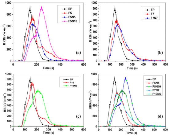
Figure 1.
Heat release rate (HRR) of different samples. (a) HRR of epoxy resin (EP), F5, F5N5, and F5N10; (b) EP, F7, and F7N7; (c) EP, F10, and F10N5; and (d) EP, F5N5, F5N10, F7N7, and F10N10.

Table 2.
Cone calorimeter data of carbon fiber (CF)/EP and carbon nanotubes (CNTs)/CF/EP composites [26].
3.1.2. Time to Ignition (TTI)
Ignition time is the time that it takes for the surface of the material is ignited when it is burned. The longer TTI becomes, the more difficult it is for the polymer material to ignite under this condition, and thus the better the fire resistance gets of the material. It is one of the important indicators to evaluate the fire resistance of polymer materials [10,25].
As can be seen from Table 2, the TTI of EP composites with CF was delayed compared to that of EP. F15 was extended up to 46 s, which was the latest to ignition. This is because CF inhibits the thermal decomposition of the EP, thus inhibiting the release of combustible gases. It can be seen from Table 2 that the TTI of the three-phase composites is also improved. The ignition time of F5N5 and F5N10 are extended to 4 s and 26 s compared to that of F5; the ignition time of F10N5 is 18 s more than that of F10, while the ignition time of F7N7 was shortened by 4 s. This shows that the three-phase composites have excellent performance in fire resistance, thereby reducing the flammability of EP.
3.1.3. Rate of Smoke Production (SPR)
SPR is defined as the ratio of extinction area to mass loss rate. The greater the SPR is, the quicker the smoke is produced when the material is burned, and the greater the risk of the material becomes in the fire [10,25].
The SPR curves for different samples are shown in Figure 2a–c are the contrast analysis curves of the three-phase material, the two-phase material, and the pure EP; Figure 2d compares the SPR of the three-phase composites with different content reinforcement. It can be seen from Figure 2a–c that the smoke rate of CF/EP is less than that of EP and the time to smoke is delayed. In contrast, the rate of smoke generated by the three-phase composites has been reduced, but the time to initially produce smoke has been advanced and the time from the beginning of the production of smoke to the peak has been significantly shortened. This shows that a certain amount of CNTs and CF can synergistically form the denser protective char layer of EP as a physical barrier to prevent gas transfer compared to CF/EP and EP. From Figure 2d, the peak value of F7N7 is the smallest, and the total smoke production is 29.24% lower than that of EP, while the total smoke production of F5N5 is the smallest, which is decreased by 43.04% than EP.
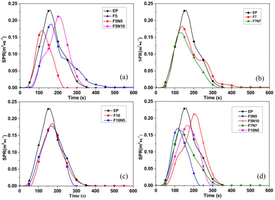
Figure 2.
Rate of smoke production (SPR) of different samples. (a) SPR of epoxy resin (EP), F5, F5N5, and F5N10; (b) EP, F7, and F7N7; (c) EP, F10, and F10N5; and (d) EP, F5N5, F5N10, F7N7, and F10N10.
It can be seen from Table 2 that, mCOY of F10 is minimum which is decreased by 6.85% compared to EP, while that of F7 and F15 are increased in the two-phase composite. It can be seen from Table 2 that mCOY of the three-phase composite is reduced compared to CF/EP. F5N10 is reduced the most, which is decreased by 12.33% than the EP. This shows that CNTs and CF can co-prevent the transfer of CO, thereby weakening the toxicity of flue gas.
3.2. SEM Morphology and Microstructure Analysis of Combustion Products
Figure 3 shows the morphology and microstructure of the combustion products after cone calorimetric test. As can be seen from Figure 3a, the combustion products of EP are relatively few, and the combustion products of Figure 3b,c are relatively complete. This is mainly due to a certain etching that is formed on the surface of the modified CF, and some polar groups are introduced to the surface of the CF with silane coupling agent making the fiber surface and resin be in full contact. thereby enhancing its interface bonding strength, so that the structure of the composites is more complete. CF will bear much heat when the material is in the ablation due to its excellent characteristics of high-temperature resistance. From Figure 3c, the structure of the combustion products of the three-phase composite is as compact as the grid, which is mainly due to the better regularity and higher crystallinity of the CNTs in the combustion process. The formation of a protective layer and the inter-layer gap with graphite protection can effectively block the heat flow [27]. On the other hand, CNTs adhere to CF when they are blended with CF. Because CNTs have a large specific surface area, the adhesion of CF to the matrix is enhanced. Following from this, the effect of the interface is enhanced, so that the CF can better exhibit heat resistance.
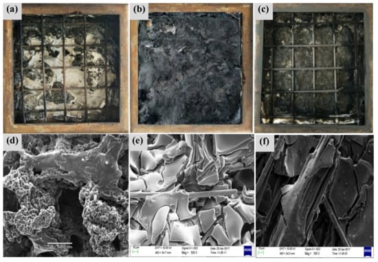
Figure 3.
SEM of the combustion products. (a) Morphology of combustion products of EP (b) CF/EP and (c) CNTs/CF/EP. (d) Microstructure of residual carbon of EP, (e) CF/EP, and (f) CNTs/CF/EP composites [26].
As can be observed from Figure 3d, the EP forms a honeycomb-like carbon layer structure during the combustion process, which is capable of isolating the generation and escape of combustible gases and inhibiting the intervention of oxygen [28,29]. It can be seen from Figure 3e that the residual carbon atoms of EP are coated on the surface of CF and are relatively complete, indicating that the CF contributes to the formation of carbon atoms in the EP, thereby reducing the amount of heat and the thermal conductivity of the combustion material, which is verified in Figure 3b. From Figure 3f, the residual carbon structure of the three-phase material is more complete. The CF surface is attached to a large number of CNTs, which shows that both of them promote the EP into carbon, which plays a better flame retardant effect.
3.3. Thermal Stability Analysis
3.3.1. Thermogravimetric Analysis
The flame retardant effect of the material has been studied above, while the flame retardant effect of the material is often related to its pyrolysis process. In order to study the thermal stability of the material and the effect of the additive on the thermal stability of the material, the samples were heated from 20 °C to 800 °C at a rate of 10 °C·min−1 by a differential thermogravimetric analyzer. The TG curves of EP, F5, F5N5, and F5N10 are included in Figure 4a, and the corresponding DTG curves are shown in Figure 4b. Figure 4c are the TG curves of EP, F7, F7N7, and the corresponding DTG curves are shown in Figure 4d. Figure 4e shows the TG curves of EP, F10, F10N5, and Figure 4f shows the corresponding DTG curves. Six partial enlarged views of vague regions are shown in every figure of Figure 4, which clearly show that there are some differences.
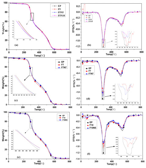
Figure 4.
Transition temperature (TG) and DTG curves of CF/EP and CNTs/CF/EP composites. (a) TG and (b) DTG curves of EP F5 F5N5 F5N10, (c) TG, and (d) DTG curves of EP F7 F7N7, (e) TG and (f) DTG curves of EP F10 F10N5.
The figures show that the thermogravimetric curves of the material also decrease stepwise as temperature increases. From Figure 4a, the TG curves of the four samples are almost coincident. It can be seen from Table 3 that the initial decomposition temperature of F5N5 and F5N10 are less than that of EP and F5, but it increases with the increase of CNTs. From Figure 4b, it can be seen that the temperature of the first peak of the three-phase composite is not changed, but the peak area is relatively small, and decreases with the increase of the CNTs, indicating that mass loss decreases. This shows that the addition of CNTs inhibits the pyrolysis of EP composites. It can be observed from Figure 4c, the mass loss rate of F7N7 is slower than EP and F7 at 20–250 °C. From Table 3, it can be seen that the initial decomposition temperature of F7N7 is higher than that of the other two materials. This shows that the addition of CNTs improved the initial decomposition temperature of the material. At 250–350 °C, the trend of all the curves in Figure 4c is nearly coincident, indicating that the maximum mass loss rate is almost the same, which coincides with the temperature of the DTG peak shown in Figure 4d. The first peak areas of F7N7 and F7 are almost similar but are smaller than that of EP. As can be seen from Figure 4e, the mass loss rate of EP is smaller than that of F10 and F10N5 at 20–250 °C. The initial decomposition temperatures of F10 and F10N5 from Table 3 are lower than that of EP. From Figure 4f, it can be seen that the area of the first peak of F10 is smaller than others indicating the mass loss is less. It is understood from Table 3 that the temperature increased at this time. This shows that the addition of CNTs and CF under this proportion synergistically inhibits the pyrolysis of EP composites.

Table 3.
T5%, Tmax and T95% of different samples [26].
3.3.2. Pyrolysis Kinetics Analysis
The thermal stability of the composites was calculated by Coats–Redfern method. The thermal stability of the composites was analyzed from the mathematical point of view by the apparent activation energies. The Coats–Redfern method is a classical integral method for calculating the single heating rate in pyrolysis kinetics. And when the material consists of one or more irreversible reactions, the pyrolysis kinetic expression is divided into two types [30].
When n = 1,
When n ≠ 1,
where α is the decomposition rate, T is the temperature corresponding to the decomposition rate, β is the heating rate, and R is the gas constant (8.314 J mol−1 K−1), n is the reaction order.
Figure 5 shows the curves obtained by fitting the pyrolysis data by the Coats–Redfern method, where n = 1 and n = 0, respectively, to determine the effect of the value of n on the results. When n = 1, and are plotted to produce a straight line with a slope of . When n = 0, the straight line can be calculated in the same way. The apparent activation energy of different specimens can be calculated as shown in Table 4. The value of α is based on TG and DTG curve data, followed by the selected mass loss of 0.05, 0.1, 0.2, 0.3, 0.5, 0.6, 0.7.
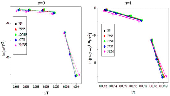
Figure 5.
Pyrolysis kinetics fitting curve of different samples.

Table 4.
The apparent activation energy of different samples from the way of Coats–Redfern.
As shown in Figure 5, the pyrolysis curve of the material exhibits two slopes, indicating that the pyrolysis process should include two stages. The first stage is mainly pyrolysis of EP. The main chain of the EP group is decomposed into a volatile gas at a relatively low temperature, and the main chain with a high bonding pressure in EP is broken at the higher temperature, resulting in an increase in mass loss, which corresponds to the first peak of DTG in Figure 4b. The second stage is the residual carbon oxide decomposition in the air atmosphere, which is consistent with the study of Carmen Branca et al. [30,31]. CF and CNTs do not participate in the reaction due to their excellent high-temperature resistance characteristics within the temperature range. The apparent activation energy of the pyrolysis of the material in Table 4 shows that the varying tendency of the apparent activation energy of the material is consistent regardless of the value of n, except that the activation energy of n = 0 is smaller. This shows that the value of n does not have much effect on the thermodynamics of the material. When n = 1, the activation energy of EP in the first stage is 101.0 kJ·mol−1. The apparent activation energy of F7N7 is 2.7 kJ·mol−1 more than EP, while the remaining three-phase composite is reduced. The activation energy of the three-phase composites in the second stage is all higher than EP. This is mainly due to that EP is burned out, while CF and CNTs can protect EP from combustion to an extent. In summary, a certain amount of CNTs and CF can synergistically inhibit the generation of free radicals activated by EP, thereby reducing its pyrolysis.
3.4. Mechanical Properties Analysis
In order to study the effect of the reinforcements on the mechanical properties of the composites, the tensile and flexural strength of different samples were tested by tensile and flexural tests. From Figure 6a, the tensile strength of CF/EP composites decreases first and then increases, and the tensile strength of F10 is the largest, which is 5.9% larger than that of EP. In the three-phase composites, the tensile strength of F5N5 is the largest, which was increased by 19.2% more than the matrix. F7N7 and F10N5 were smaller than the matrix, while it can be found that the tensile strength of the composites gradually increased with the increase of CNTs. This suggests that the addition of CNTs can improve the tensile properties of the material. From Figure 6b, the flexural strength of all materials showed a tendency to rise first and then decrease. In the two-phase system, when the CF was 0.5 wt %, the flexural strength reached 89.69 MPa, while F5N5 and F5N10 were decreased. With the increase of CF, the flexural strength was smaller. The flexural strength of F7 was reduced to 65 MPa, which was smaller than that of the matrix. The flexural strength of F7N7 was the largest and up to 104 MPa, which was improved by 50.7% more than that of EP. Flexural strength of F10N5 was also larger than F10. This indicates that a certain proportion of CNTs and CF can fully exert their mechanical synergistic effects. The reinforcement is mainly dependent on the bond strength of the interface. According to the stress transfer theory, when the composite is subjected to stress, the load is applied to the resin matrix, and then the stress will be transferred to the reinforcement by the matrix through the interface. The reinforcement played a role in the dispersion of force to a certain extent [32]. From the chemical bond theory, the functionalized CNTs can react with the modified CF to produce some kind of bonding through hydroxyl groups and other functional groups. CNTs can react with EP through their epoxy groups to form a three-dimensional network of solidified materials, resulting in an increase in the interfacial bonding strength between the substrate and the reinforcement [33]. The unique nanostructures of CNTs and the high strength of CF are the basis of mechanical enhancement.
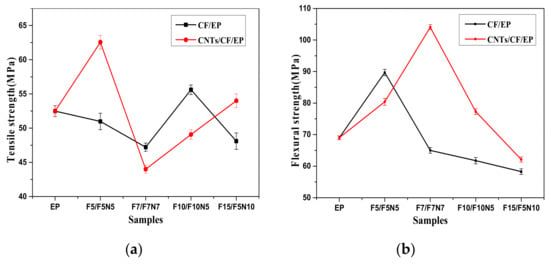
Figure 6.
Tensile and Flexural strength of samples. (a): Tensile strength (b): Flexural strength.
As shown in Figure 7a,b are the mechanical section of EP and CF/EP; Figure 7c,d are the mechanical section of CNTs/CF/EP at the magnification of 2.0 KX and 5.0 KX. As seen in Figure 7a, the cross-section of EP is relatively smooth, and the crack is less and extends in the same direction as the brittle fracture. It can be seen from Figure 7b that, when CF is 1.0 wt %, the carbon fibers dispersed in the resin are lessened. Some holes appear on the fracture surface, which is obviously caused by the desorption of the fiber. It can be seen in Figure 7c that CNTs are dispersed uniformly around the CF and EP except for some white areas which are not clearly scanned. The crack propagates in the direction of the force of CF, which is in line with the stress transfer theory. This demonstrates that CF can enhance the mechanical properties of EP. Since the interface between the fiber and the resin is poor under some certain conditions, the fiber is pulled out to form a hole in the EP. By zooming in (Figure 7c), the distribution of CNTs can be seen in Figure 7d. It can be seen that the CNTs are extracted in the crack, that is, CNTs act as a stress transfer in the process of forming the crack to further dispersing the stress acting on EP. It is the synergy between micron and nanoscale that further enhances the mechanical properties of EP.
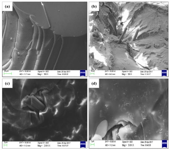
Figure 7.
Mechanical Section of CNTs/CF/EP composites from SEM. (a) EP (b) CF/EP composites (c,d) CNTs/CF/EP composites [26].
4. Conclusions
CF/EP and CNTs/CF/EP composites were prepared by solution blending. The flame retardancy and thermal stability of the composites were measured by cone calorimeter and thermogravimetric analyzer. The mechanical properties were tested by tensile and flexural tests. The results show that there is a synergistic effect between CNTs and CF, and the flame retardant enhancement and smoke suppression for EP composites are more obvious than that of CF/EP. Some findings are as follows:
The heat release rate of F7N7 is the minimum, which is 34.65% less than that of EP and 12.12% less than that of F7. The peak rate of smoke production of F7N7 is the smallest. The total smoke production of F5N5 is the smallest which is 43.04% lower than EP. Mean carbon monoxide production of F5N10 is reduced the most which is decreased by 12.33% than EP.
The initial decomposition temperature of F7N7 is about 14 °C higher than that of F7, and its temperature is not improved effectively compared with EP, but the mass loss at Tmax is obviously reduced. The apparent activation energy of F7N7 is 2.7 kJ·mol−1 more than EP. Finally, the thermal stability of EP is associated with the ratio of CNTs to CF.
The mechanical tests show that the mechanical properties are not affected while the flame retardancy is improved, and the CNTs and CF have a certain synergistic effect on the mechanical properties of the EP.
Author Contributions
Conceptualization, G.-q.C. and G.-q.Z.; Methodology, G.-q.C. and G.-q.Z.; Validation, G.-q.C., Y.G. and G.-q.Z.; Formal analysis, G.-q.C.; Investigation, G.-q.C.; Resources, G.-q.Z.; Data curation, G.-q.C., J.Z., S.G.; Writing—original draft preparation, G.-q.C.; Writing—review and editing, G.-q.C., G.-q.Z., Y.G., J.Z., S.G.; Supervision, G.-q.Z.; Project administration, G.-q.Z.; Funding acquisition, G.-q.Z.
Funding
This work was supported by the National Key Research and Development Plan (Project No. 2016YFC0802900) and supported by the Future Scientists Program of “Double First-Class” of China University of Mining and Technology (Grant No. 2019WLKXJ055). And the APC was funded by the National Key Research and Development Plan (Project No. 2016YFC0802900).
Acknowledgments
We acknowledge some experimental supports from Wang of Shenyang aerospace university. Also Xuelin Cui and Meili Dong helped us a lot for our experiments and we thank them here.
Conflicts of Interest
The authors declare no conflict of interest.
References
- Newcomb, B.A. Processing, structure, and properties of carbon fibers. Compos. Part A 2016, 91, 262–282. [Google Scholar] [CrossRef]
- Carolan, D.; Ivankovic, A.; Kinloch, A.J. Toughened carbon fibre-reinforced polymer composites with nanoparticle-modified epoxy matrices. J. Mater. Sci. 2017, 52, 1767. [Google Scholar] [CrossRef]
- Guo, J.; Lu, C.; An, F. Effect of electrophoretically deposited carbon nanotubes on the interface of carbon fiber reinforced epoxy composite. J. Mater. Sci. 2012, 47, 2831. [Google Scholar] [CrossRef]
- Tan, Y.; Shao, Z.-B.; Yu, L.-X.; Xu, Y.-J.; Rao, W.-H.; Chen, L.; Wang, Y.-Z. Polyethyleneimine modified ammonium polyphosphate toward polyamine-hardener for epoxy resin: Thermal stability, flame retardance and smoke suppression. Polym. Degrad. Stab. 2016, 131, 62–70. [Google Scholar] [CrossRef]
- Lin, J.S. Effect of polypyrrole deposition of carbon fiber on the thermal expansion of carbon fiber-epoxy composites. J. Polym. Res. 1999, 6, 237. [Google Scholar] [CrossRef]
- Li, M.; Wang, S.-K.; Gu, Y.-Z.; Zhang, Z.-G. Study on progressive reinforcement of carbon nanotubes and their composites. Acta Aerosp. Sin 2014, 10, 2699–2721. [Google Scholar]
- Kostopoulos, V.; Baltopoulos, A.; Karapappas, P.; Vavouliotis, A.; Paipetis, A. Impact and after-impact properties of carbon fibre reinforced composites enhanced with multi-wall carbon nanotubes. Compos. Sci. Technol. 2010, 70, 553–563. [Google Scholar] [CrossRef]
- Naveed, A.; Shafi, S.; Khan, U.; Kim, J.-K. Experimental torsional shear properties of carbon fiber reinforced epoxy composites containing carbon nanotubes. Compos. Struct. 2013, 104, 230–238. [Google Scholar]
- Díez-Pascual, A.M.; Naffakh, M.; Marco, C.; Gómez-Fatou, M.A.; Ellis, G.J. Multiscale fiber-reinforced thermoplastic composites incorporating carbon nanotubes: A review. Curr. Opin. Solid State Mater. Sci. 2014, 18, 62–80. [Google Scholar] [CrossRef]
- Dong, L.-B. Preparation and Properties of Carbon Nanotubes Modified Carbon Fiber/Epoxy Composites; Tianjin University: Tianjin, China, 2014. [Google Scholar]
- Bai, J.; Su, Z.; Zha, J.; Dichiara, A.; Li, W. On improvement of mechanical and thermo-mechanical properties of glass fabric/epoxy composites by incorporating cnt-AL2O3 hybrids. Compos. Sci. Technol. 2014, 103, 36–43. [Google Scholar]
- Saba, J.; Magga, Y.; He, D.; Miomandre, F.; Bai, J. Continuous electro deposition of polypyrrole on carbon nanotube–carbon fiber hybrids as a protective treatment against nanotube dispersion. Carbon 2013, 51, 20–26. [Google Scholar] [CrossRef]
- Bekyarova, E.; Thostenson, E.T.; Yu, A.; Kim, H.; Gao, J.; Tang, J.; Hahn, H.T.; Chou, T.-W.; Itkis, M.E.; Haddon, R.C. Multiscale carbon nanotube-carbon fiber reinforcement for advanced epoxy composites. Langmuir ACS J. Surf. Colloids 2007, 23, 3970. [Google Scholar] [CrossRef] [PubMed]
- Shi, X.-H.; Chen, L.; Liu, B.-W.; Long, J.-W.; Xu, Y.-J.; Wang, Y.-Z. Carbon fibers decorated by Polyelectrolyte complexes toward their epoxy resin composites with high fire safety. Chin. J. Polym. Sci. 2018, 36, 1375–1384. [Google Scholar] [CrossRef]
- Zhuo, D.; Wang, R.; Wu, L.; Guo, Y.; Ma, L.; Weng, Z.; Qi, J. Flame retardancy effects of graphene nanoplatelet/carbon nanotube hybrid membranes on carbon fiber reinforced epoxy composites. J. Nanomater. 2013, 2013, 1–7. [Google Scholar] [CrossRef]
- Shakeel Ahmad, M.; Farooq, U.; Subhani, T. Effect of multiwall carbon nanotubes on the ablative properties of carbon fiber-reinforced epoxy matrix composites. Arab. J. Sci. Eng. 2015, 40, 1529–1538. [Google Scholar] [CrossRef]
- Hesami, M.; Bagheri, R.; Masoomi, M. Combination effects of carbon nanotubes, MMT and phosphorus flame retardant on fire and thermal resistance of fiber-reinforced epoxy composites. Iran Polym. J. 2014, 23, 469–476. [Google Scholar] [CrossRef]
- Wu, Q.; Zhu, W.; Zhang, C.; Liang, Z.; Wang, B. Study of fire retardant behavior of carbon nanotube membranes and carbon nanofiber paper in carbon fiber reinforced epoxy composites. Carbon 2010, 48, 1799–1806. [Google Scholar] [CrossRef]
- Biswas, B.; Kandola, B.K. The effect of chemically reactive type flame retardant additives on flammability of PES toughened epoxy resin and carbon fibre-reinforced composites. Polym. Adv. Technol. 2011, 22, 1192–1204. [Google Scholar] [CrossRef]
- Singh, A.K.; Parhi, A.; Panda, B.P.; Mohanty, S.; Nayak, S.K.; Gupta, M.K. Aligned multi-walled carbon nanotubes (MWCNT) and vapor grown carbon fibers (VGCF) reinforced epoxy adhesive for thermal conductivity applications. J. Mater. Sci. Mater. Electron. 2017, 28, 17655–17674. [Google Scholar] [CrossRef]
- Tariq, F.; Shifa, M.; Baloch, R.A. Mechanical thermal properties of multi-scale carbon nanotubes-carbon fiber-epoxy composites. Arab. J. Sci. Eng. 2018, 43, 5937–5948. [Google Scholar] [CrossRef]
- Xiaohui, S. Study on the properties of surface flame retardant modified carbon fiber/epoxy resin composites. Chinese chemical society 2017 national polymer academic papers conference summary-theme N: Flame retardant molecular materials. Chin. Chem. Soc. Polym. Sci. Comm. Chin. Chem. Soc. 2017, 1. [Google Scholar]
- ISO 5660-1:2015. Reaction-to-Fire Tests—Heat Release, Smoke Production and Mass Loss Rate—Part 1: Heat Release Rate (Cone Calorimeter Method) and Smoke Production Rate (Dynamic Measurement); International Organization for Standardization: Geneva, Switzerland, 2015.
- GB/T 2567-2008 Test Methods for Properties of Resin Casting Body. Available online: https://www.chinesestandard.net/PDF/English.aspx/GBT2567-2008 (accessed on 9 April 2009).
- Mouritz, A.P.; Gibson, A.G. Fire Properties of Polymer Composite Materials; Springer: Dordrecht, The Netherlands, 2006. [Google Scholar]
- Chai, G.-Q.; Wang, Z.; Zhang, X. Study of the flame retardant properties of short carbon fiber–reinforced epoxy composites. High Perform. Polym. 2018, 30, 1027–1035. [Google Scholar] [CrossRef]
- Qiu, S.; Wang, X.; Yu, B.; Feng, X.; Mu, X.; Richard, K.; Yuen, K.; Hu, Y. Flame-retardant-wrapped polyphosphazene nanotubes: A novel strategyfor enhancing the flame retardancy and smoke toxicity suppression of epoxy resins. J. Hazard. Mater. 2016, 325, 327–339. [Google Scholar] [CrossRef] [PubMed]
- Juan, D. Study on preparation and combustion properties of intumescent flame retardant epoxy resin composites. Qingdao Univ. Sci. Technol. 2014, 201, 7835–7841. [Google Scholar]
- Jia, P.; Liu, H.; Liu, Q.; Cai, X. Thermal degradation mechanism and flame retardancy of MQ silicone/epoxy resin composites. Polym. Degrad. Stab. 2016, 134, 144–150. [Google Scholar] [CrossRef]
- Wu, Y.; Zhu, J.; Wang, X. Flame Retardant and Pyrolysis Kinetics of Phosphonitrile-containing Epoxy Resin. Polym. Mater. Sci. Eng. 2016, 32, 54–58. [Google Scholar]
- Branca, C.; Di Blasi, C.; Galgano, A.; Milella, E. Thermal and kinetic characterization of a toughened epoxy resin reinforced with carbon fibers. Thermochim. Acta 2011, 34, 53–62. [Google Scholar] [CrossRef]
- Dong, L.X.; Dai, G.Z.; Zhou, X.F.; Liu, L.L.; Ni, Q.Q. Stress distribution of the composites reinforced by slub-like short fibers. Key Eng. Mater. 2007, 84, 389–391. [Google Scholar] [CrossRef]
- Zheng, G.D.; Zhang, Q.J.; Deng, H.Y. Effect of different functionalized carbon nanotubes on mechanical properties of MWCNTs-carbon fiber/epoxy composites. Acta Mater. Compos. Sin. 2015, 32, 640–648. [Google Scholar]
© 2019 by the authors. Licensee MDPI, Basel, Switzerland. This article is an open access article distributed under the terms and conditions of the Creative Commons Attribution (CC BY) license (http://creativecommons.org/licenses/by/4.0/).