Abstract
Currently, the optical components of a camera embedded in the device constrain its overall thickness. Moreover, if the camera is strongly shaken, the lens and sensor may be misaligned, resulting in a defocusing effect. In this paper, we propose a novel lensless-camera communication model, which removes the lens of camera, therefore decreasing the overall thickness of the device without affecting communications. To decode the images captured by the lensless camera, a decoding algorithm aided by back propagation (BP) neural network was designed, which recognizes the blurred image patterns efficiently. To adapt to time-varying environments, an adaptive training sequence adjustment mechanism was designed. Simulation results show that the proposed image decoding algorithm presents a good bit-error-rate (BER) performance. The proposed system has robust movements and provides resilience to interference, benefiting from the neural network and the designed algorithm.
1. Introduction
The high popularity of communication devices and the natural integration with new technologies, known as the “internet of things”, optical camera communications (OCC) [1,2] has become a promising technology in the field of visible light communications (VLC). In addition, IEEE 802.15.7r1 as the official standard of OCC further promotes OCC standardization development [3]. In the future, OCC is expected to be a candidate for VLC used in some low-speed communication services.
One shortcoming of OCC is that the optical components of the camera embedded in the electronic device greatly increase the thickness of the device, affecting overall appearance [4]. The camera thickness of most mobile devices currently on the market is greater than 5 mm [5]. If the optical components were removed without affecting communications, it would be possible to create ultra-thin cameras, which would facilitate the use of small cameras, endoscopes, pill cameras, and body microscopes. Moreover, the authors of [6] proposed a method for lensless photography, which eliminated the need for lenses by utilizing computation and coded apertures in front of the image sensor. Inspired by their research, we propose a new lensless-camera communication system model to achieve communications in a new and effective way.
Figure 1a shows the proposed model of optical camera communications, which works in a half-duplex mode. The access point (AP) and terminal device both consist of a LED (as the transmitter) and a lensless camera (as the receiver). The transmitter can be a lighting LED light or the signal light of the communication device using white or any color. During communications, the up link (terminal to AP) only transmits control information. The model can be applied to some low-speed communication occasions, such as smart supermarkets or museums. Customers can use their electronic devices to download advertisements, news data, or obtain a URL link from the light source.
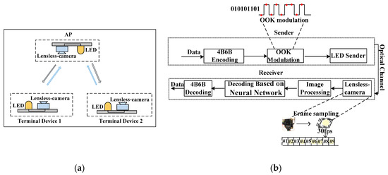
Figure 1.
Lensless camera communication system: (a) Lensless camera communication model; (b) proposed system block diagram. AP: access point; LED: light-emitting diode; OOK: on-off keying.
For OCCs that use standard cameras, the image captured by the receiver contains a light source and its surrounding scenes. Accordingly, positioning or locating the light source on the image is important to decoding it, which currently is implemented by a template matching method [7]. However, when the terminal device and AP have relative movements during communications, the light source must be searched and extracted in a timely fashion; accordingly, template matching method becomes complex and inefficient. Additionally, interference lights and time-varying environments also degrade communication performance of OCC. In contrast, the decoding method used in [8], targets a stationary communication case.
Interested in a new design for OCC, we propose a lensless camera-based OCC in this paper; we focus on decoding the special image captured by our camera. We designed an algorithm based on the back propagation (BP) neural network for image decoding. The captured images by our receiver are light spots on objects; accordingly, all the details are blurred. Accordingly, our neural network-based decoding algorithm can work efficiently. To make our decoding algorithm maintain better performance in time-varying environments, an adaptive training sequence adjustment mechanism was designed. Similar to [9], 4B6B coding and on-off keying (OOK) modulation were used, as shown in Figure 1b.
Our main contributions can be summarized as follows: (1) We propose a novel optical camera communication model, which uses a lensless camera as the receiver to decrease the overall thickness of the device without affecting communications. (2) In consideration of the special features of the image captured by the lensless camera, we designed a decoding algorithm based on the BP neural network, which recognizes light source patterns in complex conditions (e.g., ambient light, bad weather, movement of communication devices). The simulation results show the reliable performance of our system. (3) To adapt our decoding algorithm to the time-varying environments, we designed an adaptive training sequence adjustment mechanism.
2. Proposed Scheme
We propose an image decoding algorithm based on the BP neural network, which is suitable for most indoor and outdoor environments. Moreover, to improve the functionality of our decoding algorithm in time-varying environments, we propose an adaptive training sequence adjustment scheme.
2.1. Image Decoding Algorithm
Our image decoding algorithm is based on the BP neural network, which includes two stages. One is image preprocessing, the other is neural network training.
Figure 2 shows four images of the same sender captured by two different receivers. Figure 2a is the “on” image (communication light source is on) captured by a camera with lens; Figure 2b is the “off” (communication light source is off) image captured by a camera with lens. The image quality is fine. The white LED is used as the communication light source. The blue LED is used as an interference light source. To decode the data for these images, the communication light source should be identified first; accordingly a light source positioning procedure should be carried on. As a result of the interference and the relative movements between light source and receiver, the positioning algorithm is complex. Figure 2c is the “on” image captured by a lensless camera, and Figure 2d is the “off” image captured by a lensless camera. No real image of object could be captured, only the blurred, shape-less light spot surrounding the object. In fact, the essential component of OCC is the use of the camera as a receiver to identify an on/off state of a light source; detail of the image is not important at this stage of OCC. From this angle, our lensless receiver is suitable for OCC and could realize decoding easily. Without a positioning process, our algorithm realizes the decoding with the help of the BP neural network, which could identify the difference between two images, the image with “on” communication light and the image with “off” communication light. The proposed algorithm can work under the interference as long as the interference light does not change quickly. Additionally, the algorithm has robust movements because the position of the LED on the image is not important.
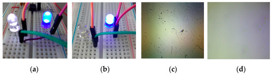
Figure 2.
Comparisons of images captured by different cameras: (a) “on” image captured by a camera with lens; (b) “off” image captured by a camera with lens; (c) “on” image captured by a lensless camera; (d) “off” image captured by a lensless camera.
2.1.1. Image Preprocessing
In actual applications, the LED transmitter may use colored or white LED bulbs to transmit different types of signals (e.g., warning or danger signals). Any image can be decomposed into three component images (Y, Cb, and Cr) [10]. Different component images from different light sources can result in a different decoding effect in different environments. Accordingly, we first selected the appropriate component to train the neural network, then performed decoding. Figure 3a is the analysis of the “off” image of the illumination LED without ambient light interference. Figure 3b is the analysis of the “on” image of the illumination LED without ambient light interference. Figure 3c is the analysis of the “on” image of the blue LED without ambient light interference. Figure 3d is the analysis of the “on” image of the illumination LED with blue ambient light interference.
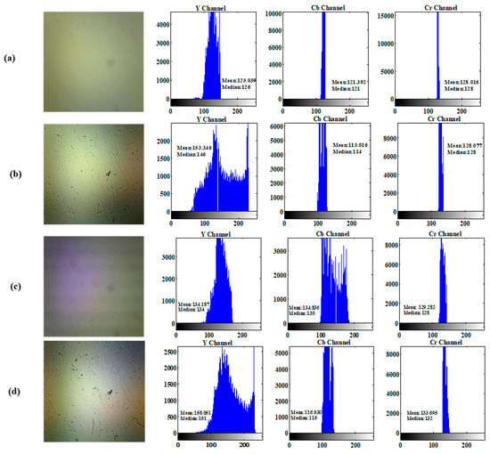
Figure 3.
YCbCr components analysis of images in different environments: (a) “off” image of the illumination LED without ambient light interference; (b) “on” image of the illumination LED without ambient light interference; (c) “on” image of the blue LED without ambient light interference; (d) “on” image of the illumination LED with blue ambient light interference.
By comparing the Y, Cb, Cr components of the captured images in different environments, we determined that we should choose the right component for a training neural network in different environments. After comparing the Y, Cb and Cr components of Figure 3a,b as well as Figure 3a,d, we found that, in these two cases, we should choose Y component for training. After comparing Figure 3a,c, we determined that the Cb component should be selected for training in this case.
2.1.2. Neural Network Training
In this stage, our main goals were to create a neural network structure that met our functional requirements and to find the best settings for the stable training process [11]. After many experiments and adjustments, in the training process, this paper adopts the fastest descent method with adaptive learning rate and additional momentum factor in the weight update process, as shown in Equation (1); the equation can prevent the network from falling into oscillations and find the minimum point more easily. The learning rate has a huge impact on the performance of the network. In different stages of training, the value of the learning rate is different, so we used the adaptive learning rate and tried to find the best settings for the training process. We used an initial learning rate 0.01 and a momentum 0.9 as well as other parameters, as shown in Table 1.
where w(k) is the weight of step k, α(k) is the learning rate of step k, ƞ is the momentum factor, and D(k) = −∂E/∂w(k) is the negative gradient of step k; E is the error function.

Table 1.
Parameters.
To maintain good decoding performance in time-varying environments, our neural network was trained periodically; accordingly, the number of images in the training set was determined by the channel condition.
2.2. Adaptive Training Sequence Adjustment Mechanism
Because the classification effect of the BP neural network is related to the size of the training set, we had to control the training sequence length to ensure the accuracy of classification without incurring too much data overhead.
In indoor working conditions, the difference between the “on” and “off” states of the LED images varies due to the change of the background scene; e.g., at night, the difference between these two types of images is obvious, but at daytime it becomes vague. The length of the training sequence should be adaptive and ensure the recognition effect of the neural network. When system works outdoors, the communication channel is more complicated due to ambient light intensity variation or bad weather (snow or rain). In this paper, an adaptive training sequence adjustment mechanism is proposed to adapt to time-varying environments.
2.2.1. Frame Structure
In our proposed system, before communications, communication parties establish connection through exchanging control frames. The structure of the control frame is shown in Figure 4. It includes “SFD” (full name is shown in Table 2), which separates the starting bits from the remaining information bits. The field “Type” differentiates control frame and data frame. The field “Subtype” consists of four bits, which indicates the types of frame. The “Duration” field of the control frame indicates the time between the end of the current control frame and the completion of data reception. Here, the “Duration” field is reserved for occasions in which multiple users have simultaneous communications in the future. The field “Length of Training Sequence”(LTS) is used by the terminal device to notify the AP the length of the training sequence in the next cycle. The LTS is “000000” if the length does not need change or if this confirmation frame comes from the AP. The field “Frame Check Sequence“ (FCS) is used to verify whether the received data is correct.

Figure 4.
Structure of control frame.
Table 2.
Special field description of the frame.
As shown in Figure 5, the field of Training sequence of data frame consists of alternating “1” and “0” bit, which makes the number of two types of images in the training set approximately the same.

Figure 5.
Structure of data frame.
2.2.2. Training Sequence Adjustment Process
In this process, after each communication is completed, the receiver determines the number of required training images according to the current bit error rate (BER); it then informs the transmitter by transmitting a control frame. In this paper, via a large number of experiments, the relationship between training sequence length and BER has been established. The main implementation process is shown in Figure 6 and Figure 7 and described below.
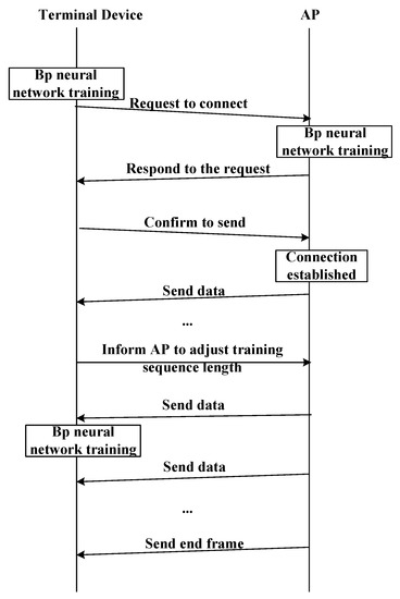
Figure 6.
The process of establishing the connection.
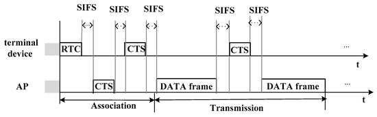
Figure 7.
The process of adjusting the training sequence. SIFS: short inter frame space; RTC: request to connect; CTS: confirm to send.
- (1)
- Before the terminal device requests the connection, the terminal first captures several image frames sent by the AP for training its neural network to decode the data later;
- (2)
- Then, the terminal device sends a request frame to the AP;
- (3)
- The AP receives several request frame images for training the neural network at the AP end;
- (4)
- The AP sends information to confirm the connection after receiving the request frame.
- (5)
- Once the terminal device receives the confirmation message from AP, it sends CTS frame to the AP.
- (6)
- If the AP receives the CTS frame, which means the connection is established, the AP begins to send data to the terminal device.
- (7)
- After each communication, the receiver will determine the training sequence length required for the next communication according to the accuracy of the data received in this communication, and send CTS frame to notify AP to adjust the length of the training sequence.
- (8)
- Finally, either party of the communication can send the end frame to end the communication.
3. Lensless Camera Communication System Experimental Platform
To evaluate the BER performance of our system when used indoors and outdoors, we set up a lensless camera communication system, as shown in Figure 8. The receiver of the system is a lensless camera. To obtain the lensless camera, we used the camera module on the microcontroller, of which the lens is detachable. Then, we used a LED (as sender) to send signals. During the experiments, we made the lensless camera move slowly in a short range and used the lensless camera to capture the images of the LED on the sending end. It can be seen from the simulation results that the BER can meet the communication requirements. Therefore, our decoding algorithm can resist the movement of communication devices.
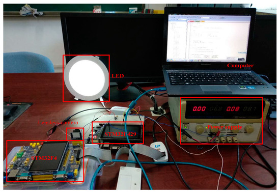
Figure 8.
Overall lensless camera communication experimental system.
3.1. Hardware Design of Sender Module
The sender consists of a microcontroller, an amplifier circuit, and a switch circuit. In the experimental process, we selected the STM32F429 as microcontroller. The MAX4427 chip was used in the amplification circuit. The microcontroller is used to generate modulated signals that are then amplified by the amplification chip to form 2A sink current. We also selected an IRF54ON FET with a short response time (about 20 ns) as the switch to drive the LED to transmit modulated visible light signals. Figure 9 shows the circuit diagram of the sender.
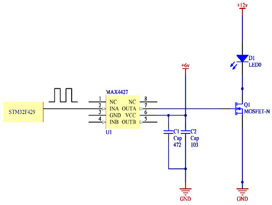
Figure 9.
The circuit diagram of the sender.
3.2. Hardware Design of the Receiver Module
We obtained a lensless camera receiver by implementing the OV2640 camera module on the ALIENTEK Explorer STM32F4 board, for which the lens of the camera module was moved. The frame rate of the lensless camera was set to 30 fps. During the experiments, we used the lensless camera to capture the images of the LED on the sending end.
4. Results and Discussion
This section analyzes the BER performance of the proposed model. Here, we compare the BER performance of our system when using our decoding algorithm or threshold determination decoding method. The threshold determination decoding method is to compare the average gray value of an image with a fixed threshold value. If the average gray value of the image is greater than the threshold value, it will be judged as “on” image; otherwise, it will be judged as “off” image. For the indoor situation, we analyze the BER performance under different background brightness. For the outdoor situation, we analyze the decoding accuracy of our decoding algorithm on snowy channel condition. Table 3 lists the key experimental parameters.
Table 3.
Experimental parameters.
Figure 10 compares the BER performance of two cases, one in which the receiver is stationary and the other in which the receiver is slowly moving within a certain range. It can be seen from the results that the difference in BER performance between the two cases is not obvious, which indicates that our proposed decoding algorithm is not sensitive to terminal device movement. Therefore, in comparison with some image decoding algorithms, our image decoding algorithm can resist the movement of communication devices.
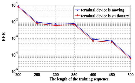
Figure 10.
Comparison of bit-error-rate (BER) performance between moving terminal device. and stationary terminal device.
Figure 11 shows the images of LED transmitter captured by our lensless camera when the indoor background brightness (the brightness of the “off” image) was around 0.5. Figure 11a is the “off” image of LED light without noise light source interference; Figure 11b is the “on” image of LED light without noise light source interference; Figure 11c is the “on” image of the blue LED light without noise light source interference; and Figure 11d is the “on” image of LED light with blue noise light source interference. Here, we use different colors of LED lights as transmitters to simulate the signal lights of communication devices. During the experiments, our images were captured while the lensless camera was moving slowly within a certain range, indicating we took the movement of communication devices into account.
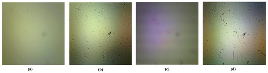
Figure 11.
Images of of LED lights indoor during day: (a) “off” image of LED light, (b) “on” image of the LED light, (c) “on” image of the blue LED light, (d) “on” image of LED light with blue noise source interference.
Figure 12a presents the diagram of BER using our proposed decoding algorithm. It shows that the BER is related to the indoor brightness and the length of the training sequence. Within a certain range, as the number of the training images increases, BER decreases. Moreover, normally the BER in high indoor brightness environments will be slightly higher than the BER in low indoor brightness environments. This is because the higher the indoor brightness, the more severely the image is disturbed by ambient light, e.g., when sunlight shines into a room during the day. However, in general, our decoding algorithm works well under the condition of blue noise light source interference, as seen in Figure 11d.
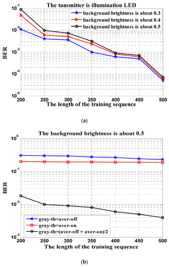
Figure 12.
BER performance using different decoding algorithms indoors (the transmitter is illumination LED light): (a) the BER using our proposed decoding algorithm under different indoor brightness and (b) the BER using threshold determination method at different thresholds.
Figure 12b shows the curves of BER using the threshold determination decoding method, of which the thresholds are different. The first threshold is set to the average gray value of all “off” images of the training set; the second threshold is set to the average gray value of all “on” images of the training set; the third threshold is set to the average of the gray value mean of all “off” images in the training set; and the gray value mean of all “on” images in the training set. As seen in Figure 12b, the BER curves under the first two thresholds are significantly higher than the third threshold, which indicates that BER performance is very relevant to the threshold setting method in this decoding method. However, it is difficult to find a good threshold setting method that can adapt to environmental changes. Overall, this method cannot resist the interference of background light source to provide a reliable performance for our system.
Figure 11 and Figure 12 shows that our system can work well indoors in most cases. To analyze the performance of our system while working outdoors, we simulated the images taken in the bad weather (e.g., snowy days) and performed simulation analysis.
The snowflake density factor in Figure 13 indicates the intensity of the snowflake distribution. The larger the factor is, the denser the snowflake distribution is. Figure 14a shows our image decoding algorithm can meet the communication requirements on snowy days as long as the appropriate length of the training sequence is provided. However, Figure 14b shows the poor BER performance of the threshold determination method in the outdoor snowy environment.
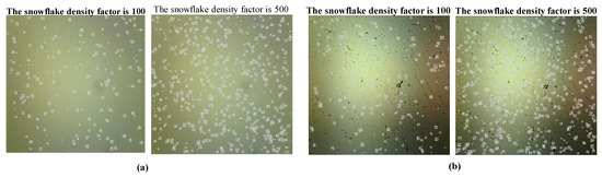
Figure 13.
Images of the states of the illumination LED light on snowy days: (a) “off” image of the illumination LED light and (b) “on” image of the illumination LED light.
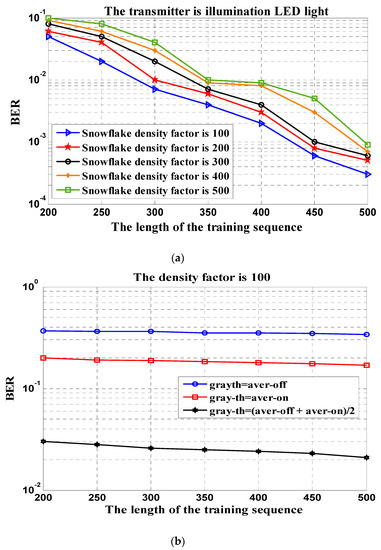
Figure 14.
BER performance using different decoding algorithms on snowy days (the transmitter is illumination LED light): (a) the BER using our proposed decoding algorithm and (b) the BER using threshold determination method at different thresholds.
Figure 15 describes the BER performance of the blue LED at the transmitting end, which is regarded as the signal light of communication device. We can see the “on” image of the blue LED captured by the lensless camera from Figure 11c. Figure 15a shows that our proposed image decoding algorithm can also work well when the transmitter is a blue LED. Figure 15b indicates that the decoding performance of the threshold decision method is not good when the blue LED light is used as the sender.
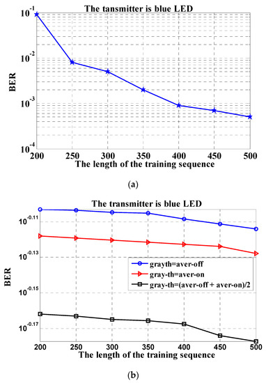
Figure 15.
BER performance using different decoding algorithms indoors (the transmitter is blue LED light): (a) the BER using our proposed decoding algorithm and (b) the BER using threshold determination method at different thresholds.
5. Conclusions and Future Work
In this paper, we propose a lensless camera-based communication system model, which provides a model for new designs for OCC systems. To evaluate the indoor and outdoor BER performance of our system when using the proposed decoding algorithm, we set up an experimental platform and performed the simulations. For indoor communications, we analyzed the BER performance of our proposed decoding algorithm when the transmitter was white lighting LED light or blue LED light. For outdoor communications, we analyzed the BER performance of snowy days with different snowflake densities. We concluded that the decoding algorithm using the BP neural network that we designed can adapt well to the changes of the time-varying environment, guaranteeing the reliable performance of the communication system over error probability.
In future work, we will consider high-order modulation to increase the data rate. Additionally, we will also propose some effective methods to improve the communication distance of our system.
Author Contributions
Conceptualization, X.C., S.Z. and Y.Z.; Methodology, X.C. and S.Z.; Software, S.Z.; Formal Analysis, X.C., S.Z. and Y.Z.; Investigation, H.S. (Hanyang Shi); Data Curation, S.W.; Writing—Original Draft Preparation, S.Z.; Writing—Review & Editing, X.C., S.Z. and H.S. (Hongliang Sun); Visualization, Y.Z.; Project Administration, Y.Z.
Funding
This research was funded by Jilin Scientific and Technological Development Program under Grant 20180101040JC.
Conflicts of Interest
The authors declare no conflict of interest.
References
- Saha, N.; Le, N.T.; Ifthekhar, M.S.; Jang, Y.M. Survey on optical camera communications: Challenges and opportunities. IET Optoelectron. 2015, 9, 172–183. [Google Scholar] [CrossRef]
- Yamazato, T.; Takai, I.; Okada, H.; Fujii, T.; Yamazato, T.; Takai, I.; Okada, H.; Fujii, T.; Yendo, T.; Arai, S. Image-sensor-based visible light communication for automotive applications. IEEE Commun. Mag. 2015, 52, 88–97. [Google Scholar] [CrossRef]
- Nguyen, T.; Islam, A.; Yamazato, T.; Jang, Y.M. Technical Issues on IEEE 802.15.7m Image Sensor Communication Standardization. IEEE Commun. Mag. 2018, 56, 213–218. [Google Scholar] [CrossRef]
- Kim, G.; Isaacson, K.; Palmer, R.; Menon, R. Lensless Photography with only an image sensor. Appl. Opt. 2017, 56, 6450–6456. [Google Scholar] [CrossRef] [PubMed]
- Zhu, Y.; Chen, F.; Yin, S. Design of cell phone camera lens based on glass aspheric lenses. J. Sciencepaper Online 2011, 44, 2926–2943. [Google Scholar]
- Huang, G.; Jiang, H.; Matthews, K.; Wilford, P. Lensless imaging by compressive sensing. In Proceedings of the 2013 IEEE International Conference on Image Processing, Melbourne, Australia, 15–18 September 2013; p. 2101. [Google Scholar]
- Guo, S. Device Pairing Using Visible Light Communications. J. Dep. Inf. Commun. Syst. 2014, 51, 86–96. [Google Scholar]
- Novak, M.; Wilfert, O.; Simicek, T. Visible light communication beacon system for internet of things. In Proceedings of the 2017 Conference on Microwave Techniques (COMITE), Brno, Czech Republic, 20–21 April 2017. [Google Scholar]
- Karunatilaka, D.; Zafar, F.; Kalavally, V.; Parthiban, R. LED Based Indoor Visible Light Communications: State of the Art. IEEE Commun. Surv. Tutorials 2015, 17, 1. [Google Scholar] [CrossRef]
- Shaik, K.B.; Ganesan, P.; Kalist, V.; Sathish, B.S.; Jenitha, J.M. Comparative Study of Skin Color Detection and Segmentation in HSV and YCbCr Color Space. J. Procedia Comput. Sci. 2015, 57, 41–48. [Google Scholar] [CrossRef]
- Xiong, Z.; Chen, K.; Gu, C.; Liang, Y.; Yu, F. An algorithm of image classification based on BP neural network. In Proceedings of the 2012 IEEE International Conference on Computer Science and Automation Engineering (CSAE), Zhangjiajie, China, 25–27 May 2012; pp. 523–526. [Google Scholar]


© 2019 by the authors. Licensee MDPI, Basel, Switzerland. This article is an open access article distributed under the terms and conditions of the Creative Commons Attribution (CC BY) license (http://creativecommons.org/licenses/by/4.0/).