1. Introduction
Cranial restoration or cranial defect replacement can be defined as a medical procedure to reinstate an unhealthy or damaged region on the skull [
1]. The primary objective is the shielding of tissues and nerves within the skull, along with the realization of body shape and the achievement of mental stability in the patient [
2]. Cranial restoration is generally carried out on patients who suffer from head trauma as a result of any injury (accident), infection or congenital deformities [
3]. The skull injuries or malformation are considered as one of the most critical and worrying health concerns, which affects a large population all over the world [
4]. Moreover, the repairing of cranial abnormalities poses serious challenges, even to experienced surgeons, because the body part being operated on comprises of nerves, soft tissues, or other delicate organs, inside a confined zone [
5]. A variety of different approaches, such as autologous bone grafting [
6,
7], utilization of standard implants manufactured from traditional methods, like casting, forging, machining and powder metallurgy techniques [
8,
9], etc., were the common techniques in cranial restoration. However, in recent times, the application of these approaches has been minimized owing to their compelling drawbacks. For example, the autologous bone grafting technique involves complicated operative methods, blood loss, and pain in the patient, etc., [
10]. Similarly, the employment of regular implants, which necessitates physical bending or rearrangement using trial runs to custom fit the patient bone contour, is a time-consuming, inaccurate, and laborious approach [
11]. Furthermore, any discrepancy would result in implant failure, a greater number of amendments and psychological stress on the patient’s mind. Henceforth, to minimize disparities and conform bone contours as well as provide enhanced cosmetic output, it is imperative to make use of the concept of customized implant design [
12,
13]. The customized design of an implant can improve fitting accuracy significantly and reduces the operation time in contrast to standard plates.
The rapidly growing health care demands owing to aging, expanding the global population, etc., emphasize the importance of innovative technologies in the medical field. The unification of medical data imaging, image processing software and additive manufacturing (AM) has the potential to produce any complex structure (customized implant) with a perfect fit, which can match the bone contour and result in a trimmed appearance. The implementation of integrated techniques can save a huge cost for health systems in addition to improving the quality of life for a large population [
14]. A favorable outcome in implant reconstruction depends on several factors such as the material characteristics, implant design, fabrication method and skills of the surgeon. Certainly, the design of customized implants must conform to the individual patient’s needs, inclusive of the size, shape and mechanical properties of the implant. As a consequence of unique human anatomy, AM is very useful to accomplish patient-specific implants, matching the bone contours with a perfect fit. The AM has significantly upgraded the ability to manufacture intricate geometrical structures with precision in comparison to the conventional processing methods [
15]. It can produce sufficiently packed and graded structures with appropriate accuracy and process adaptability. The applications of AM, especially in the medical sector, have been increasing very quickly and are expected to revolutionize the health care sector. It can successfully manage the requirements of medical devices, in terms of product customization, efficient and cost-effective production, short delivery time, etc. In addition to the appropriate fabrication approach, the precise and pertinent requirements of customized implants also necessitate the implementation of relevant bio-materials. Out of the possible metallic materials that can be usedTitanium Alloy (Ti6Al4V) is considered as the most favored choice for the customized implants. This can be attributed to its biological compatibility, Osseo-integrative property, high strength to weight ratio, higher corrosion resistance, non-magnetic properties, high toughness, and mechanical resistance, etc., [
16,
17,
18].
There are a multitude of different kinds of AM technologies in the market, but all of them follow the same principle of manufacturing three-dimensional (3D) objects from computer-aided design (CAD) models by depositing the raw material in a layer by layer manner. The various AM technologies available in the market are stereolithography (SLA), fused deposition modeling (FDM), selective laser sintering (SLS), 3D printing (3DP), Electron Beam Melting (EBM), etc. These systems can be categorized depending on the bulk material (or the original state of the raw material), which can be liquid, solid or powder [
19,
20,
21]. The AM technology employed in this work is EBM in order to fabricate the customized implant. One of the primary strengths of EBM is its ability to produce parts from titanium alloys (Ti6Al4V). EBM has been widely utilized in the production of medical implants throughout Europe and the United States with a Food and Drug Administration (FDA) license [
22]. It was initially marketed in 1997 by ARCAM AB Corporation, Sweden which has acquired more than thirty international patents involving EBM science or techniques [
23]. The earlier studies have suggested EBM as a rational option for titanium alloy custom designed implants required in orthopedic, craniofacial and maxillofacial surgeries [
24,
25,
26]. Unlike other traditional methods, EBM does not possess any limitation in terms of shape constraints and can produce complicated parts with nearly perfect accuracy. Indeed, the titanium alloy (Ti6Al4V ELI) used in the current EBM process has proven to have good mechanical and chemical properties for implants [
27,
28].
In this paper, a comprehensive approach for the design, fabrication, and validation of a customized cranial implant has been developed. The primary goal of this study is the introduction of a simple method to redesign and fabricate the defective part on the skull. The AM has been combined with digital image acquisition techniques, like computed tomography (CT) to achieve the mentioned objective. This work demonstrates the route from the patient’s CT scan to the fabrication of titanium cranial implants and its validation. The DICOM (digital imaging and communication in medicine) files from CT were imported in a specific software (Mimics) and the segmentation approach was employed to cut the region of interest and produce the 3D model. The mirror reconstruction technique was utilized to generate the patient-specific implant on the injured portion of the skull. This design was then analyzed and compared with the cortical bone for mechanical properties through finite element analysis (FEA). Subsequently, the titanium cranial implant (≃1.76–2 mm thick) was fabricated from Ti6Al4V ELI powder by using EBM technology. It was finally validated and investigated for appearance, accuracy, mechanical properties, and material composition.
2. Methodology
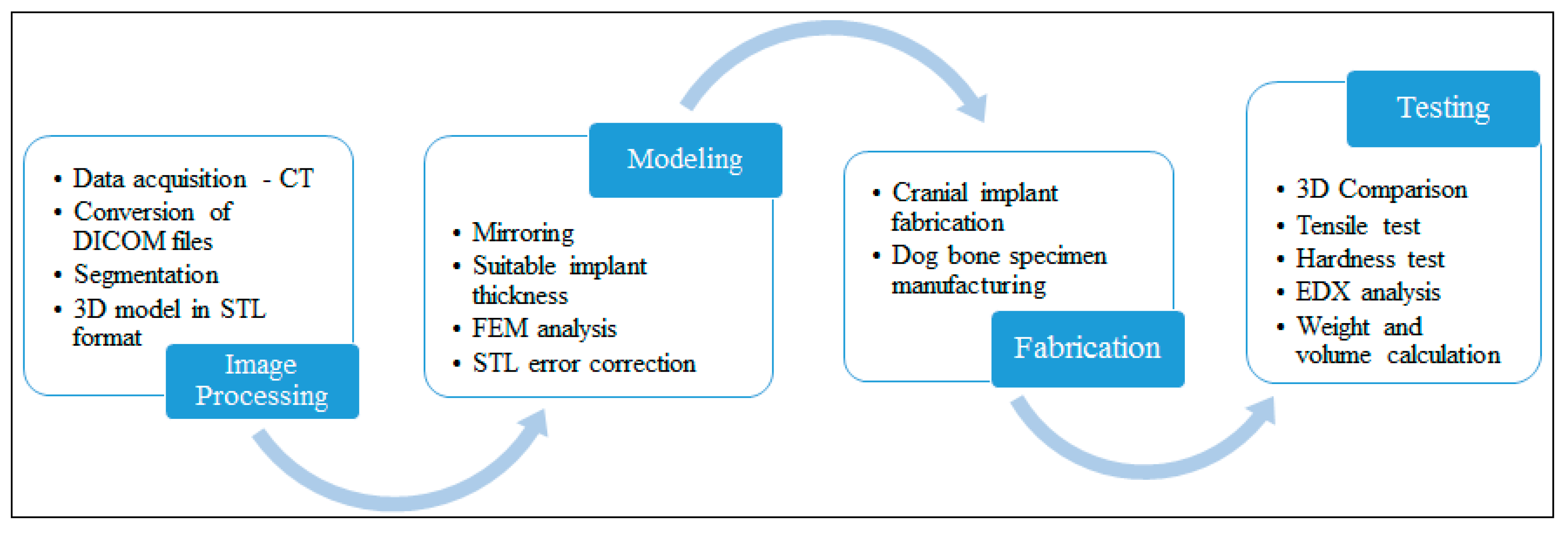
The proposed methodology for acquiring a customized cranial implant has been based on four major pillars, including image processing, modeling, fabrication, and testing. The work-flow from data acquisition to final testing can be realized in
Figure 1. The approach is exhaustive, comprising of numerous sub-procedures, such as segmentation, Standard Tessellation Language (STL) error correction, thickness reduction, etc., to ensure a dependable cranial implant. The discussion about the different steps in the methodology is presented in the following sections.
2.1. Image Processing
A cranial defect case from the University Hospital was selected to employ the proposed approach. To begin with, CT scanning of a thirty-year-old patient suffering from a sizable cranial deformity in the left parieto-temporal area was carried out. The CT data were captured by using a ProMax 3D Cone Beam CT machine (Planmeca, Helsinki, Finland). The gathered images were stored as DICOM files. These DICOM files consisted of 2D layers from all-around (front, side and back ends) the patient’s cranium. A well-known medical image processing software which is known as Mimics 17.0® (Materialize NV, Belgium), was utilized to transform the acquired DICOM files in the quintessential 3D model.
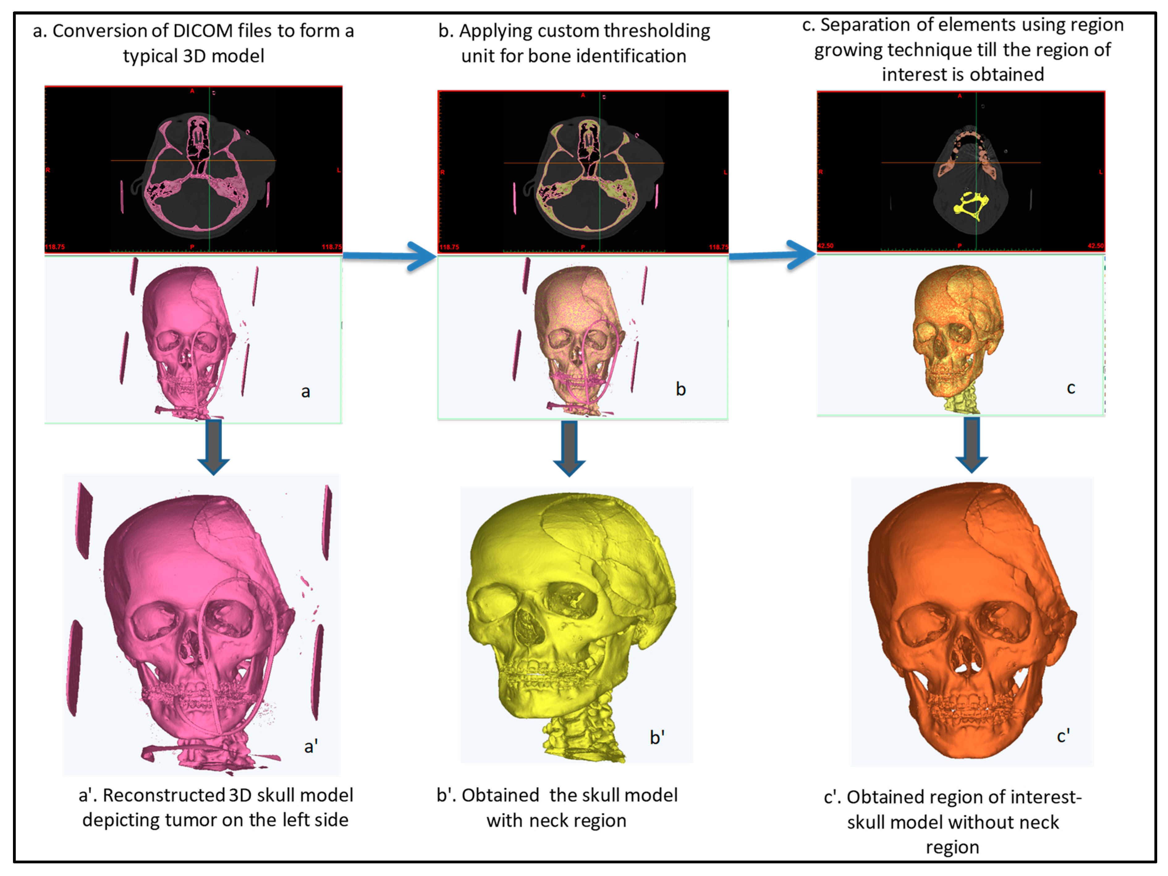
The 3D model is useful because it includes information about the patient’s bones, skin, soft tissues, etc. To access the area of interest as well as to divide the hard and soft tissues, segmentation and region growing techniques were exploited in Mimics®.
Figure 2 depicts the various steps of surface modeling from a fully scanned skull model to the region of interest. The segmentation was accomplished through the identification of image intensities in Hounsfield units (HU). The HU was used because it could quantify the attenuation coefficient of different regions in CT scan images and provided the right type of tissues. For example, bone exhibits a higher HU value in contrast to skin and soft tissues owing to its ability to absorb a greater amount of radiation. The region growing algorithm was required to minimize or remove any noise, outlier or gap in the image data, thus providing a continuous set of pixels as shown in
Figure 2a. A 3D rendered model of the patient’s cranium was obtained as shown in
Figure 2b by exploiting the reconstruction tool. The 3D surface modeling is a tiresome and tardy procedure because it has to be reworked numerous times until the desired region of interest (affected area) is realized. The finally obtained region of interest, a 3D skull model without the neck region (
Figure 2c′), was stored in the STL format for the subsequent implant modeling process.
2.2. Modeling
The main objective of this step was the designing of a customized cranial implant through the mirroring technique. Certainly, the mirror reconstruction technique can be identified as an influential and most extensively employed implant design technique in medical restorative applications, especially in animal anatomy where bi-lateral symmetry prevails [
28]. It can also be established here that the anatomical structures acquired through mirroring are practically ideal and optimal [
29,
30]. The modeling stage commenced with the importing of 3D model’s STL file (
Figure 3a) in 3–Matic 9.0
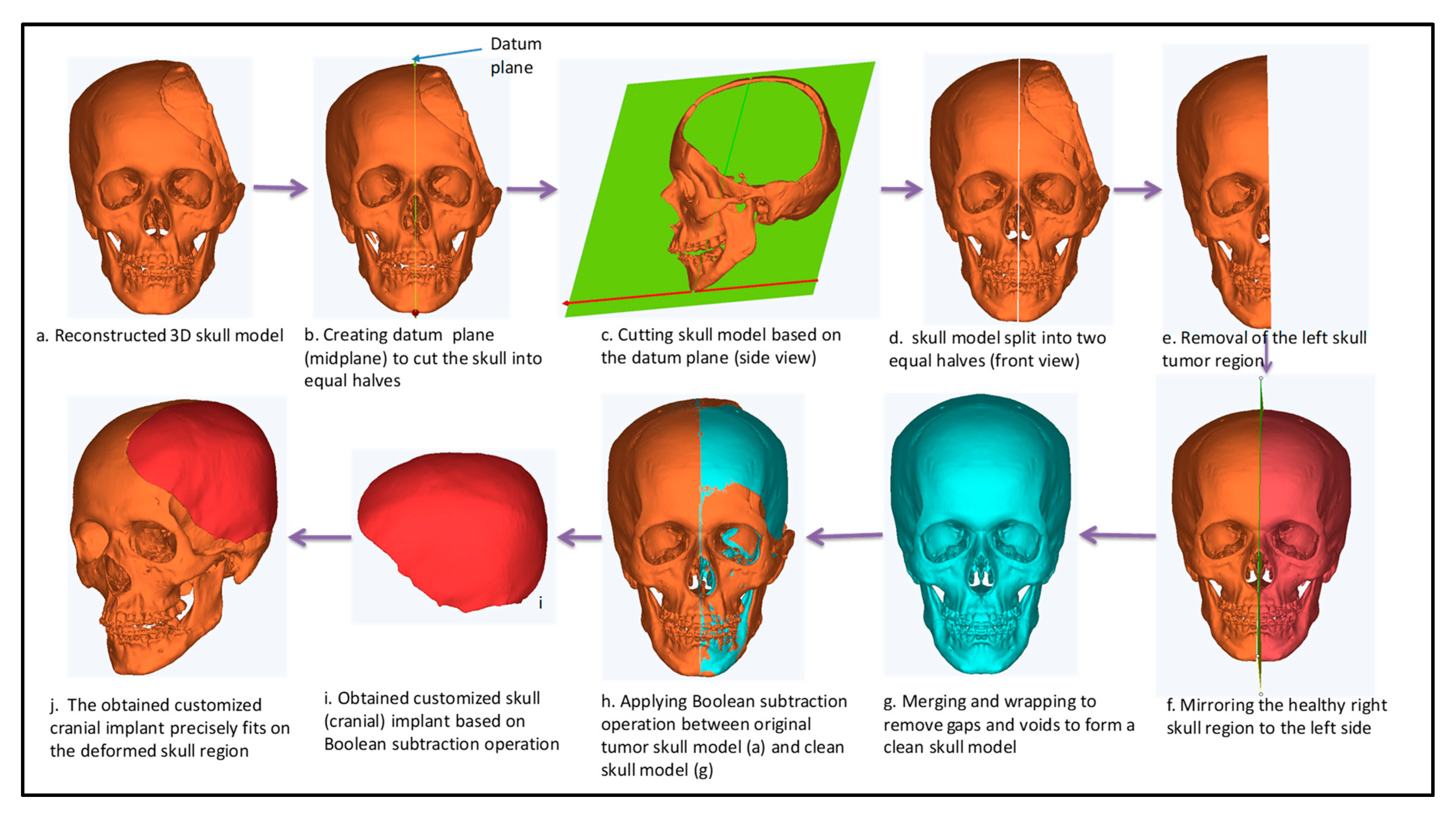
® (Materialize NV, Belgium) software. The following workflow adopted to accomplish the mirroring which assumed human anatomy to be symmetric.
The cranium was segregated through datum plane (mid-plane) after determining two maximal endpoints (
Figure 3b,c).
The deformed or the deficient left side was taken out through the cutting operation (
Figure 3d,e).
The normal or healthy bone on the contralateral side was imitated with reference across the center plane (or symmetric plane) (
Figure 3f).
Merging and wrapping operations were carried out to minimize the disparities, inconsistencies and discontinuous surfaces between them (
Figure 3g).
Consequently, a Boolean subtraction procedure (
Figure 3h) was executed among the freshly designed skull model (
Figure 3g) and the original skull containing defect (
Figure 3a).
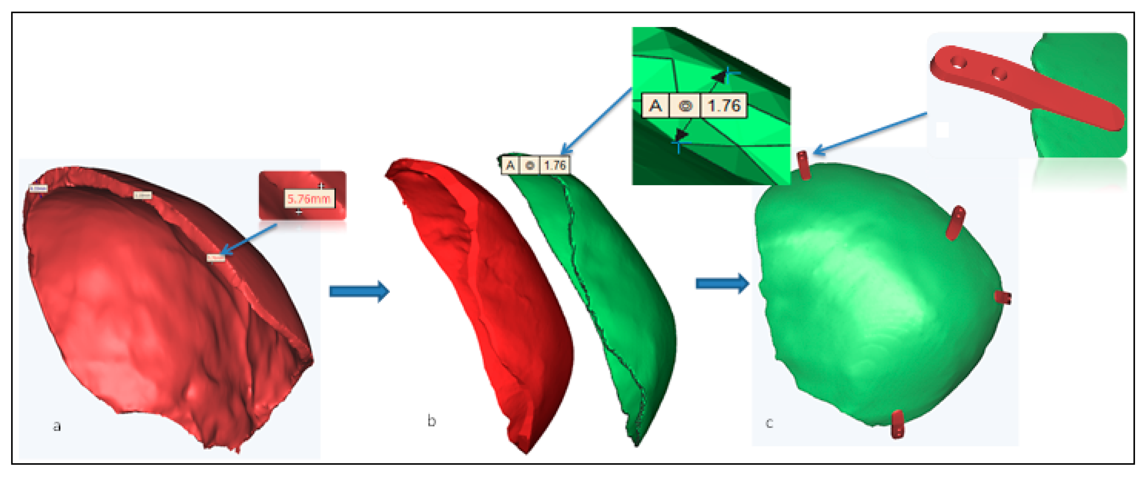
The mirroring procedure generated the tailored cranial implant (
Figure 3i) with a thickness of ≃ 5.76 mm (thickness of the cranial bone).
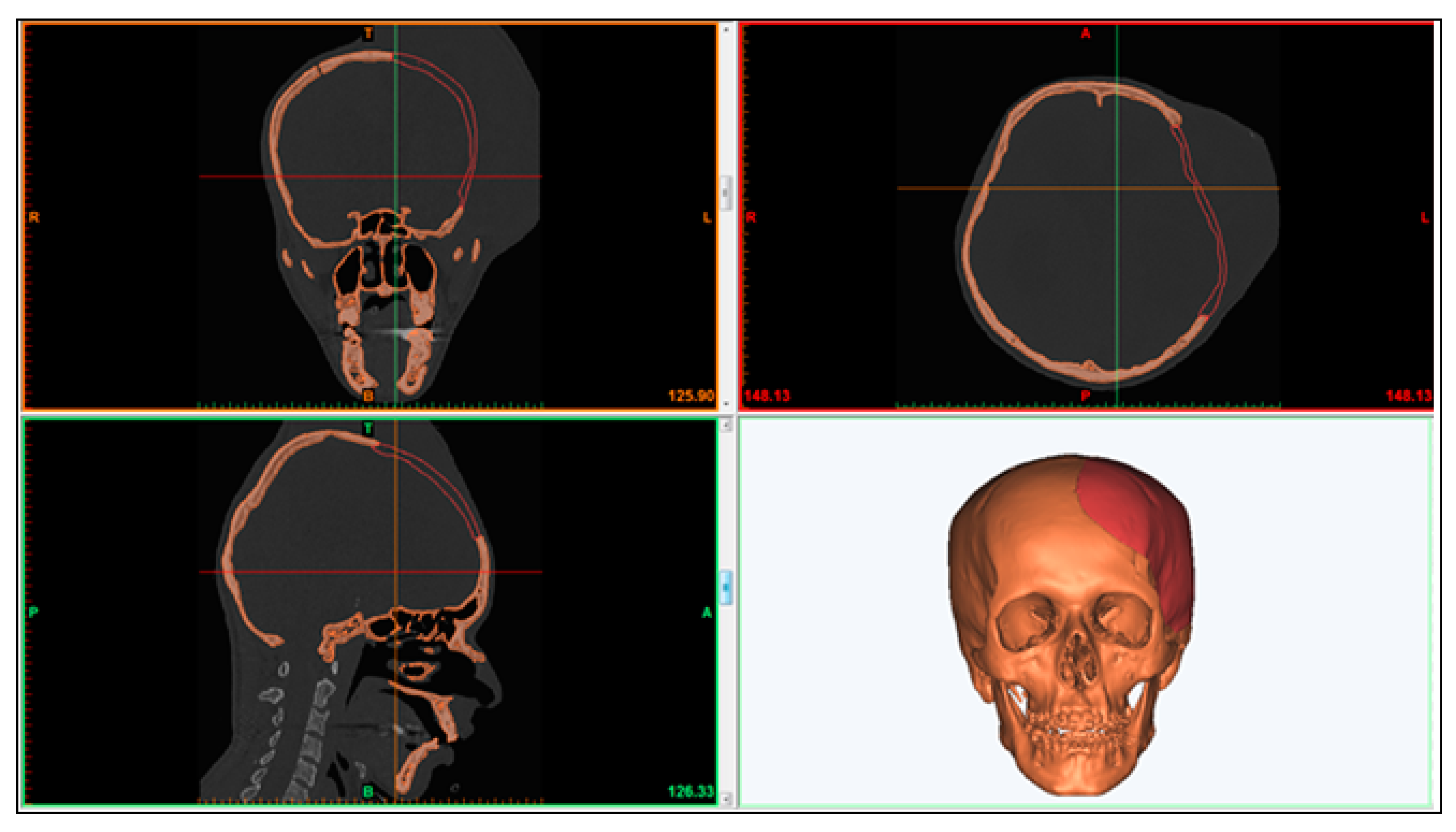
The mirrored model assured a simple and precise fitting through the edge of the defective region as well, as it resulted in an implant contour which was perfect in terms of aesthetics and appearance. An impeccable alignment of the newly designed personalized cranial implant (red area) adjacent to the defective skull region (orange region) can be seen in
Figure 4.
As a result of redundant implant thickness, the likelihood of the stress shielding effect across the surrounding bone also increased. Therefore, to minimize the thickness and weight of the implant nearer to the bone counterpart, an offset operation was implemented on the thick cranial implant (
Figure 5a,b). Finally, an implant with a thickness in the range of ≃1.76–2 mm was obtained, as shown in
Figure 5c.
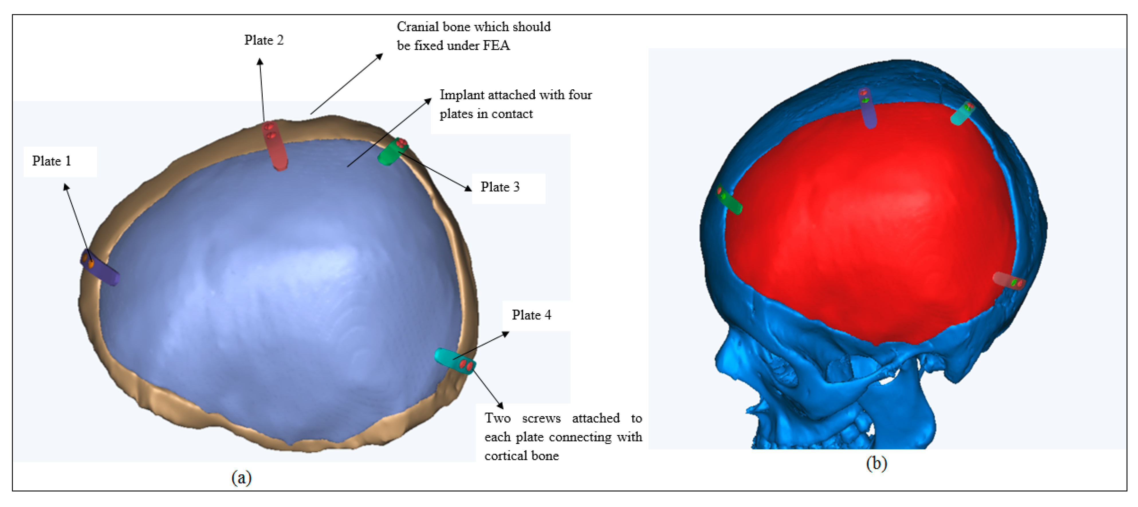
Moreover, the quadruple fixation mini-sheets with taper screw holes were also designed as shown in
Figure 6a. They were needed to achieve the stability, sturdy connection and fixation of the implant on to the cranium as shown in
Figure 6b. The tapered designed screw holes as a result of the entire sinking of the screws aided in the stability and rigidity as well as improving the patient’s comfort.
The FEA model was created to assess the biomechanical stability of the designed custom cranial implant [
31]. The pre-processing, post-processing and the execution of the developed FEA model were performed in the Abaqus software. The properties of materials designated to the FEA model are presented in
Table 1. The different material properties were assigned to different regions on the skull [
32]. The attributes of cortical bone were designated to the cranium, while Ti6Al4V ELI was assigned to the customized cranial implant [
33,
34].
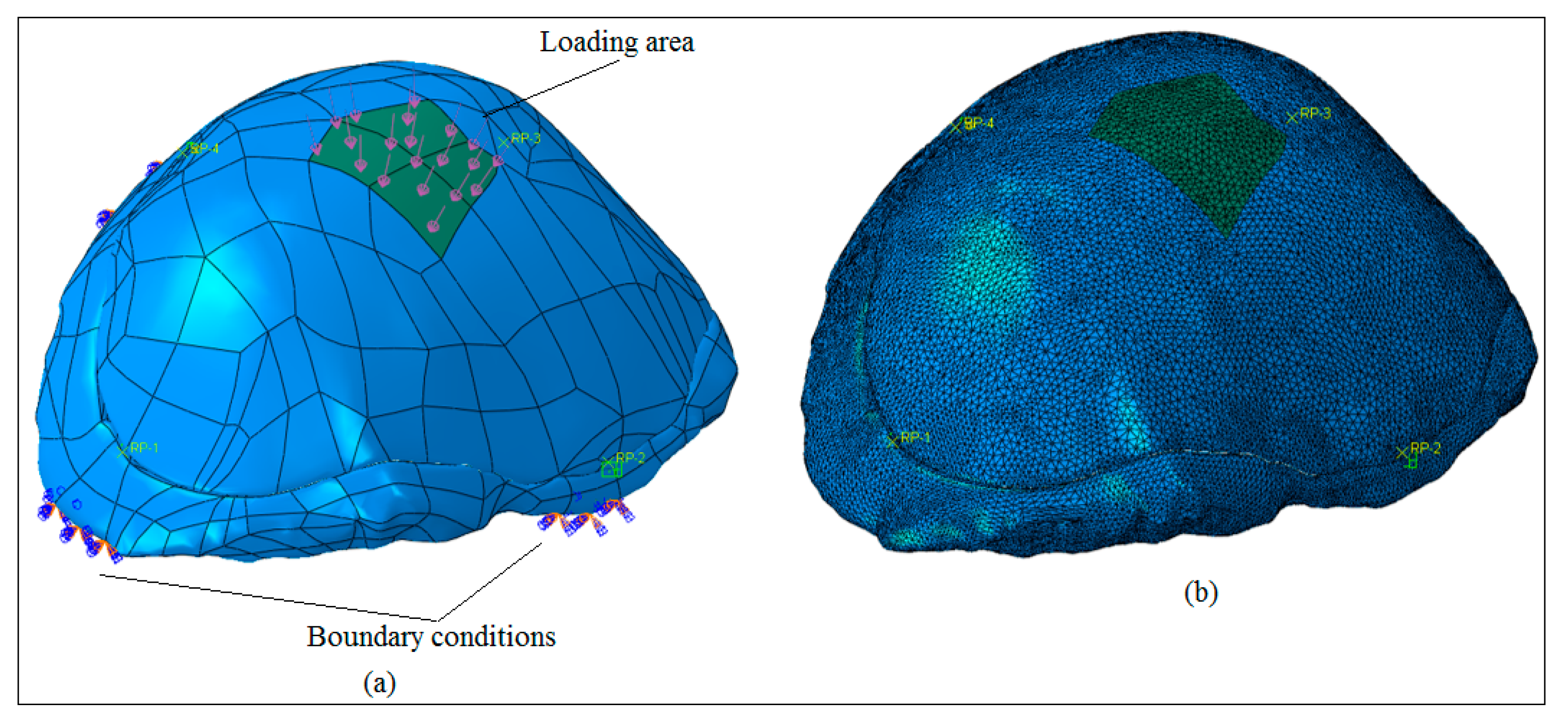
Before analyzing the FEA model, the 3D model was fixed for minor geometrical errors, including the removal of very small faces and edges on both the implant and bone section. The skull (or the cortical bone section) was fixed at four positions at the bottom as shown in
Figure 7a. A static force of 50 N was applied in the center region of the implant over an area of 550 mm
2. Moreover, the mesh-independent fasteners were used to model the joining between the implant and bone section. It is an effective approach to define an explicit connection between two or more surfaces in the same manner with a spot weld or rivet joint. Four fasteners were utilized at selected reference positions. The continuum tetrahedral quadratic elements with ten nodes (C3D10) were selected for the model as shown in
Figure 7b. To avoid mesh distortion and improve element quality, the fine mesh was generated resulting in a total of 280000 elements for the implant and bone section. The ABAQUS/STANDARD was selected as the finite element solver with static general procedure. To ensure mesh-independent results, a finer mesh model was developed and checked with the original one.
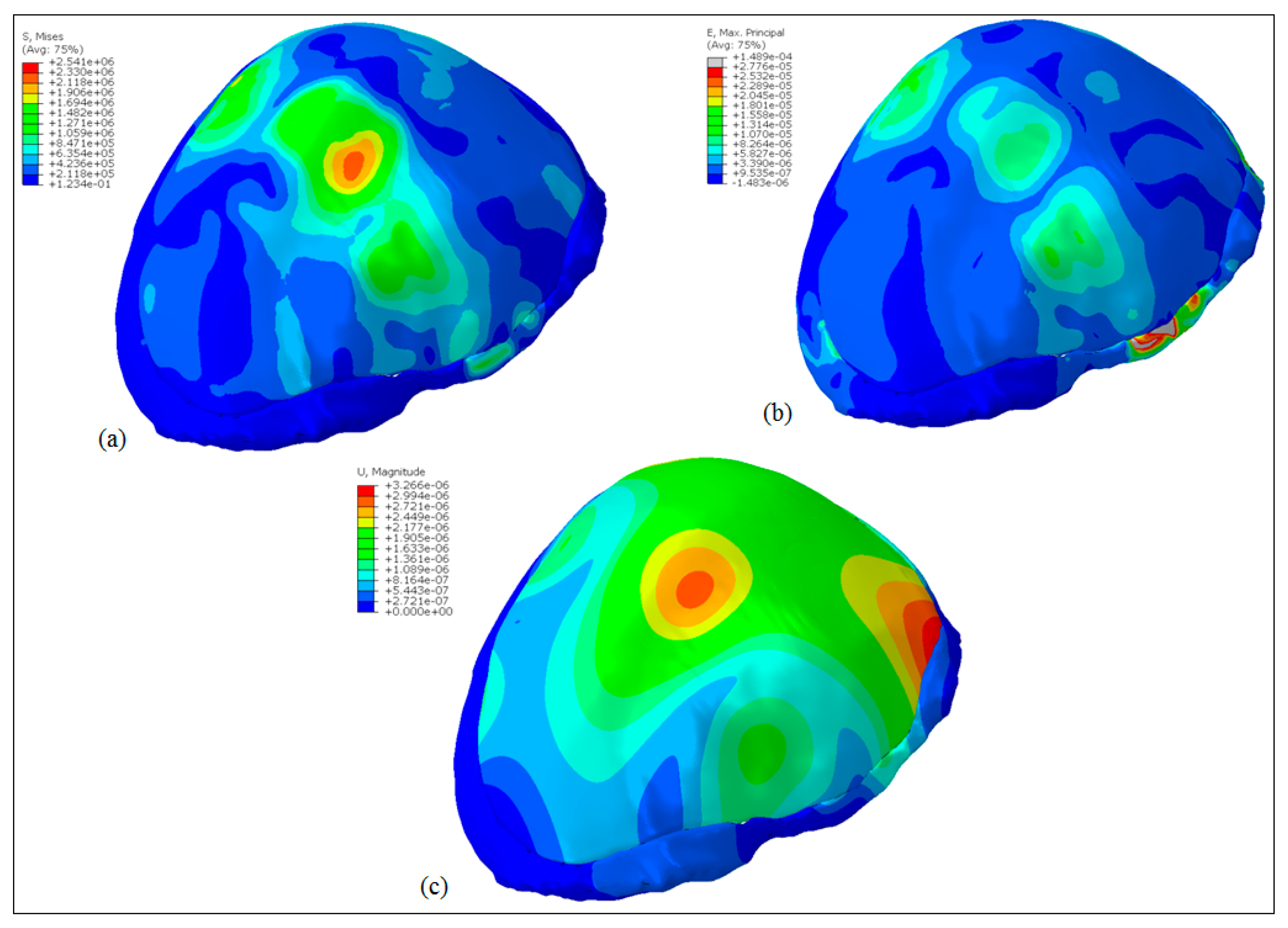
The results obtained after executing the FEA model can be realized in
Figure 8. The Von Mises stress distribution is shown in
Figure 8a and the maximum value was around 2.5 MPa which was well below the Yield strength (930 MPa) of the titanium alloy (Ti6Al4V ELI) thus ensuring the absence of any plastic deformation in the implant. Moreover, the maximum principal strain distributions in
Figure 8b marked comparatively high strained regions around fasteners and load areas. However, the overall strain levels were very low and the maximum value was around 1.49 × 10
−4. Similarly,
Figure 8c shows the deformation pattern in the implant due to the applied load. As expected, maximum deformation occurred at the load area, however, the magnitudes were very low i.e., around 3.26 × 10
−6 mm. In conclusion, the results showed that the implant design could be used satisfactorily for the replacement of the defected skull region.
The fabrication of the cranial implants was preceded by the elimination of errors in the STL file as described in
Figure S1. The errors such as overlapping, intersecting triangles, bad edges, and other defects were resolved in Magics
®. The purpose of this stage was the processing of the STL file and determining the best position and orientation for fabrication.
Once the STL models were flawless, appropriate supports were generated on the overhanging structures as shown in
Figure S2. The most suitable supports were essential to precisely build the prototype without any aberration. The support also helped in the straightforward ejection of the prototype from the building table. The support structures were also required for efficient heat transfer to minimize any distortion and to facilitate the fabrication of overhanging parts. Moreover, the support structures were attached to the cranial implant with teeth at the top and bottom for their easy removal.
2.3. Fabrication
The fabrication of the customized cranial implant and dog bone shaped specimens were carried out in this phase. The dog bone shaped specimens were needed to assess the tensile strength of the tailor-made cranial implant. The custom made cranial implant as a result of its aberrant and unsteady structure could not be analyzed with any standard mechanical testing. Moreover, there was no conclusive standard which could be employed to perform the tensile test on the customized cranial implant. Henceforth, to investigate the tensile strength of Ti6Al4V ELI material used in cranial implant, dog bone shaped specimens as per ASTM E-8 standards were designed. Certainly, several previous works can be pointed out which have also performed similar studies on titanium specimens to estimate their mechanical properties [
33,
36,
37]. There are also shreds of evidence in the literature, where dog bone shaped specimens were analyzed instead of real shapes in order to comprehend the tensile properties of a particular material. For example, Komurlu et al. [
38] recommended a dog bone shaped specimen as the ideal geometry for estimating accurate tensile results of different rock materials. The dog bone shaped specimen used in this study possessed an overall length of 100 mm, a gauge length of 25 mm and a width of 6 mm as depicted in
Figure S3. The dog-bone structure was manufactured as per ASTM E-8/E-8M/16a standard [
39,
40].
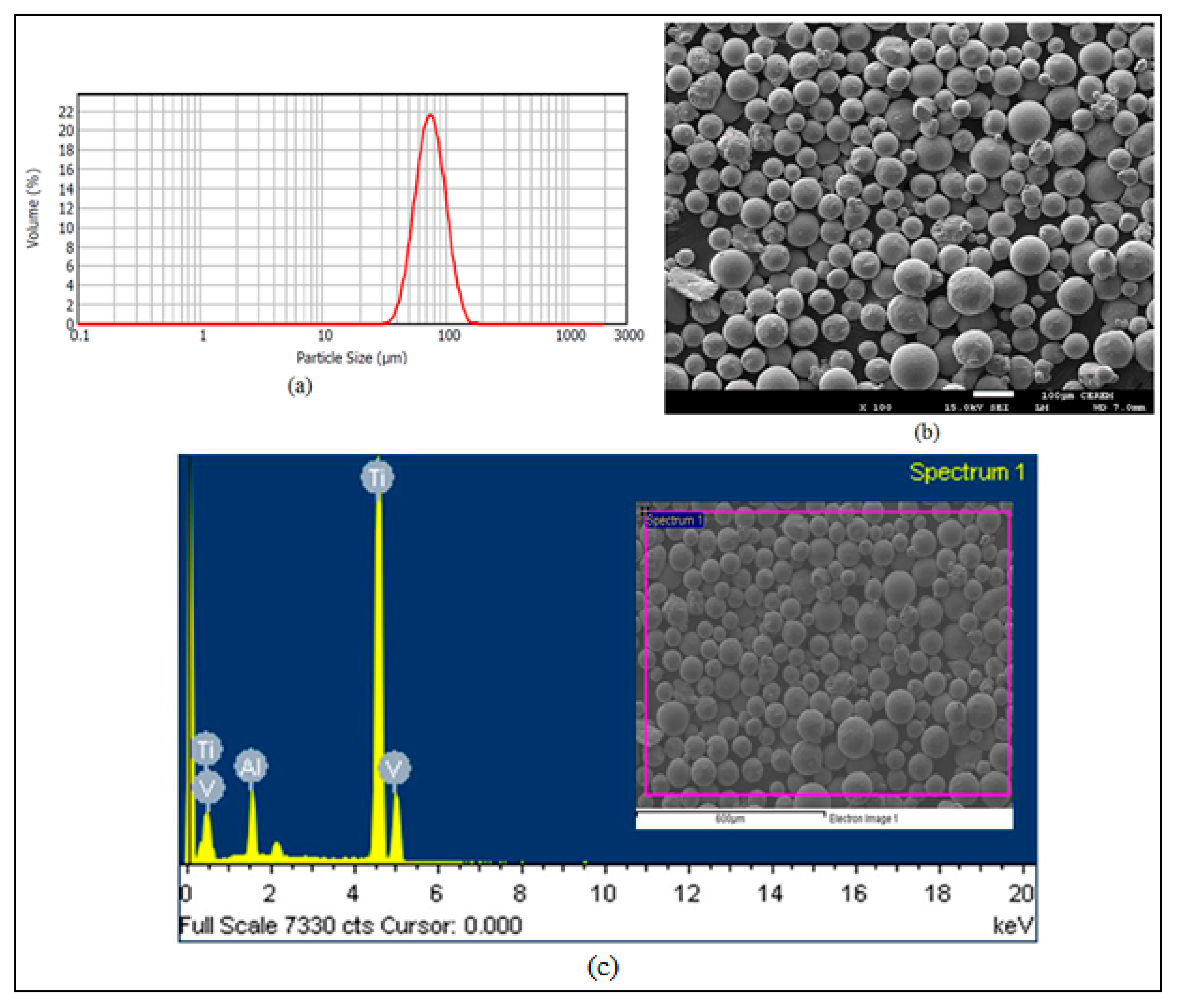
The particle size analysis as shown in
Figure 9a revealed that the titanium powder (Ti6Al4V ELI) with the particle size between 50–100 μm was utilized for the fabrication of the customized cranial implant and the dog bone specimen in this study.
Figure 9b represents the analysis of Ti6Al4V ELI powder using JOEL’s JSM-6610LV (JOEL, United States) Scanning Electron Microscope (SEM). The formation of the powder particles was primarily spherical in shape with slight variation in geometry. The chemical composition of Ti6Al4V Extra-low interstitial (ELI) as revealed in
Figure 9c was 6.04% Aluminum (Al), 4.05% Vanadium (V), 0.013% Carbon (C), 0.0107% Iron (Fe), and 0.13% Oxygen (O), with the remaining constituent as Titanium (Ti) in weight percent.
The ARCAM’s EBM machine as shown in
Figure 10 was employed for the fabrication. The fabrication in the EBM process consisted of three primary stages: (1) preheating of the metal powder, (2) scanning as well as melting of the powder and (3) lowering of the building platform along with the raking of the powder bed. At the outset, the entire Ti powder layer in the powder bed was warmed up (or preheated) through scanning at a high scan speed until the certain intended temperature (730 °C) was reached. The preheating was carried out at eighty percent of the melting temperature in order to fuse the powder particles. The preheating also aided in reducing the stresses and sintering the unbound powder particles for the retention of the consecutive powder layers. The standard ARCAM parameters, preheat-I and preheat-II were utilized during fabrication. In preheat-I, the complete powder bed was scanned and in preheat-II, the scanning was executed only in the melting region. Subsequently, a high-velocity beam of electrons scanned the metal powder line by line according to the defined CAD geometry through various lenses. The scanning and melting operation consisted of two processes, contouring and infill hatching. First, the contours were melted by using electron beams, depending on the boundary representation (or the cross-section) of the 2D slices. However, the beam current and the scan speed were raised in hatching in contrast to contouring. In order to melt and fill the area between the contours, the powder layers were screened using a snaking melt strategy in the back and forth direction. The metal powder in the contours and the hatching part was melted, leaving the rest of the powder for recycling. After the preheating and melting of the particular layer, the build platform was descended through one layer thickness (50 µm) and a fresh powder layer was supplied from hoppers and spread uniformly onto the formerly solidified layer with the help of raking blades. These three stages were reciprocated in a cycle manner until the 3D physical part was obtained.
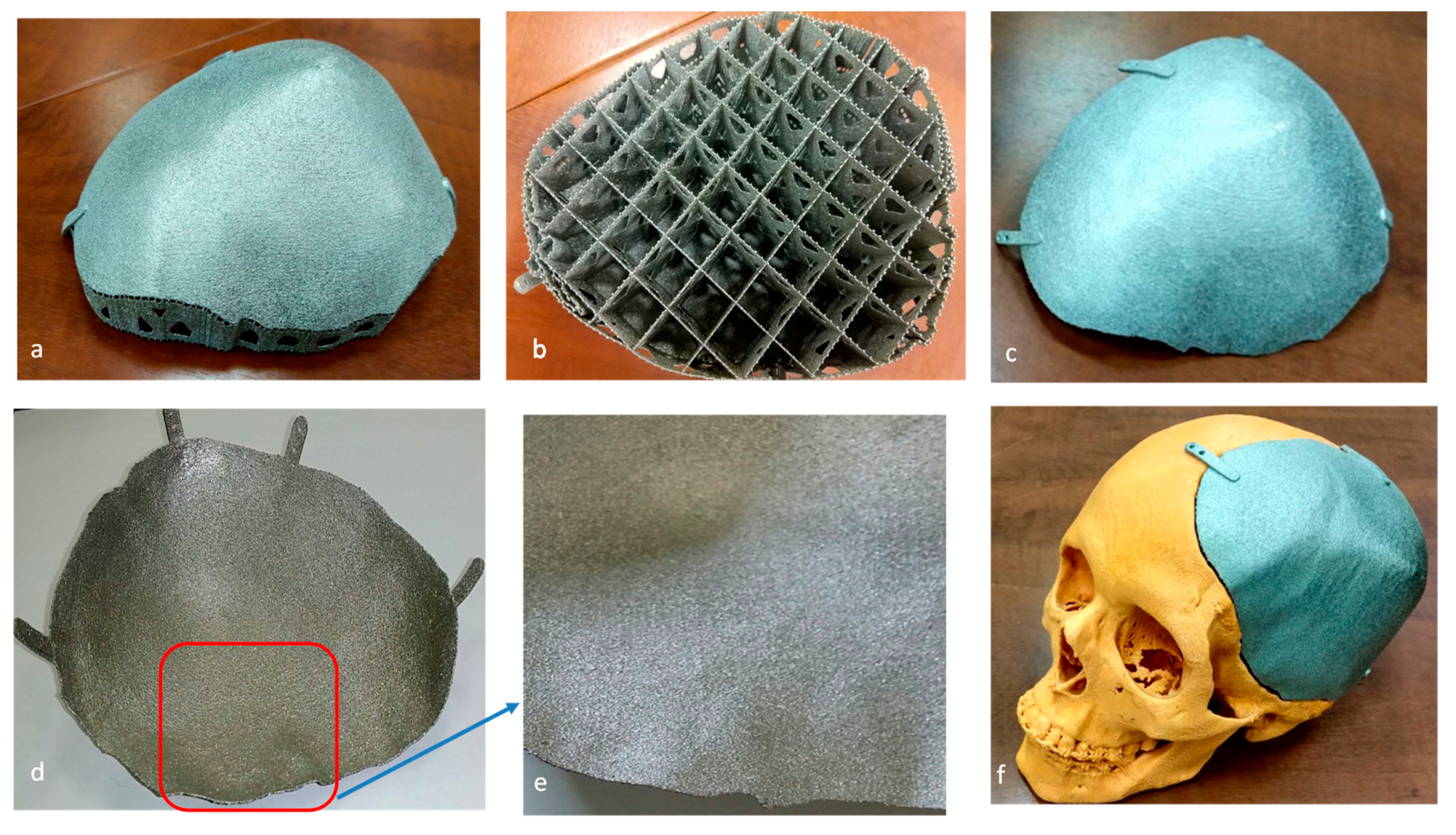
The produced EBM specimens were finally blown in a powder recovery system (PRS) using a high-pressurized air nozzle for taking out the finely trapped powder particles. The support structures (
Figure 11b) attached to the cranial implant (
Figure 11a) were removed manually using plyers and this procedure did not result in any defect on the fabricated specimen. The fabricated customized cranial implant after support removal (
Figure 11c,d) did not show any sign of burr or protrusion (
Figure 11e) on its surface. The titanium cranial implant was finally tested on the polymer skull model (
Figure 11f) for fitting evaluation. The EBM produced as-built titanium cranial implant does not require any post-processing treatment, as its surface finish is ideal for osseointegration (bone-ingrowth) [
41]. Indeed, several prior studies had established that there was no significant improvement in the adhesion or osseointegration with post-processing. An in-vivo study on rabbits using EBM produced Ti6Al4V implants exhibited similar surface chemical composition and surface roughness in contrast to wrought Ti6Al4V and machined Ti6Al4V implants [
42]. Similarly, Biemond et al. observed that the presence of coating or surface treatment of EBM fabricated implant did not result in enhanced bone in-growth or mechanical fixation strength in comparison to the as-built EBM specimen [
43]. Based on these earlier investigations, it can be inferred that the as-built EBM specimen does not require any post surface treatment if its surface roughness lies within the specified range of the EBM manufacturer. According to ARCAM, the surface roughness (Ra) of the as-built specimen should fall within the interval of 25–35 μm [
44]. Henceforth, the surface roughness of the fabricated cranial implant in this study was also measured (Ra = 25.3 μm) and found within the specified range. However, if needed, the EBM built cranial implant can be post-processed for better surface finish using plasma electro polishing [
45] and laser ablation techniques [
46,
47].
2.4. Testing and Validation
In this phase of testing and validation, the custom designed cranial implant was assessed for accuracy, appearance, and aesthetics in addition to the intrinsic investigation of the implant for tensile strength, hardness and material composition. This phase has been discussed in detail in the subsequent sections.
3. Analysis Results
The accuracy of the fabricated cranial implant was estimated by employing a 3D comparison analysis in Geomagics Control
® [
48]. It can be assumed as one of the comprehensive and dynamic techniques to graphically estimate the surface deviations between the actual object and the reference CAD model [
49]. As shown in
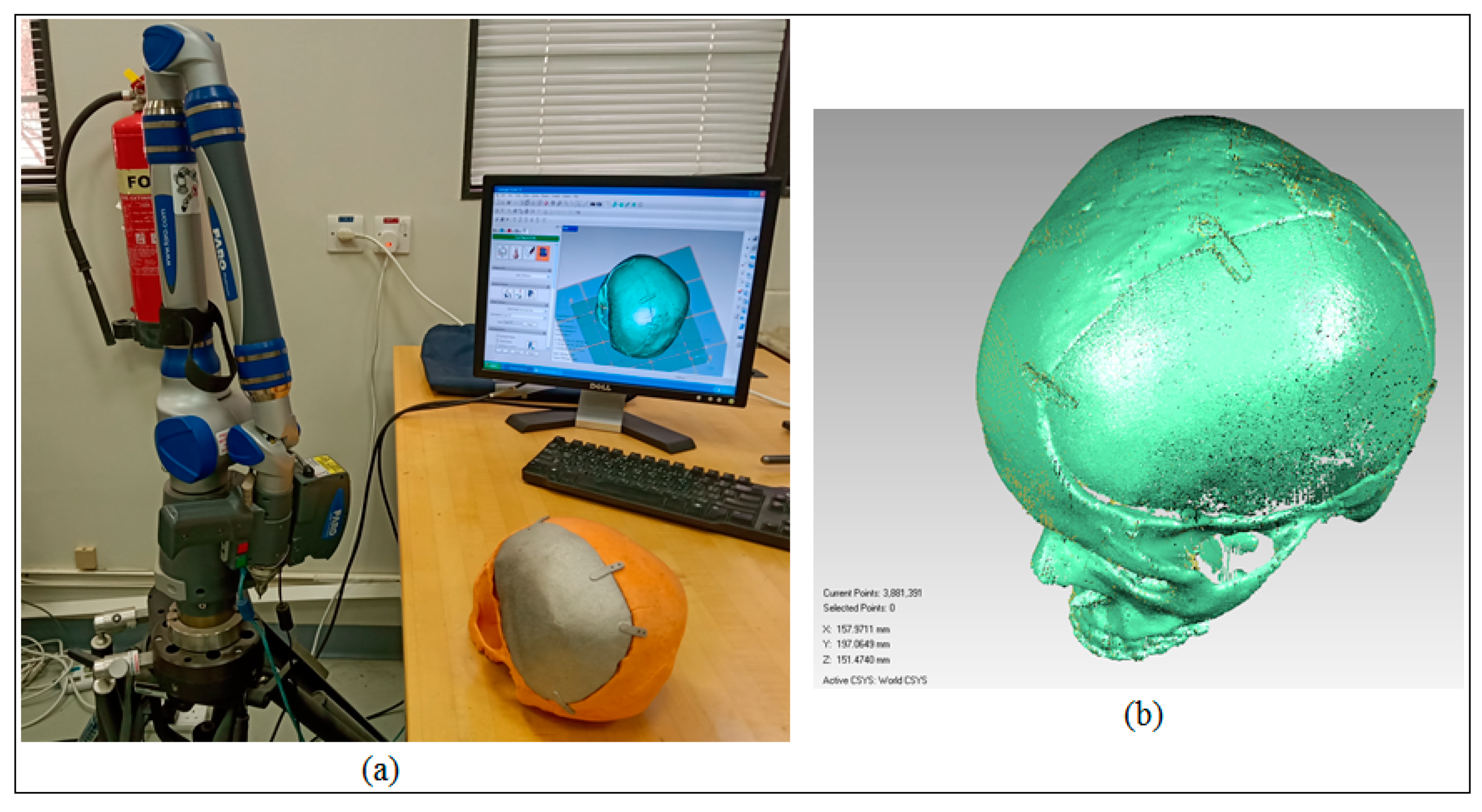
Figure 12a, the custom made cranial implant was mounted and fixed on the skull and digitized to acquire the test data. The scanning was performed by employing the laser scanner on the Faro Platinum arm (FARO, Florida, USA). The visual investigation on the actual part in conjunction with the visualization of the captured point data (
Figure 12b) revealed satisfactory appearance, aesthetics and a near perfect outer profile on the defective side of the skull when the implant was mounted on the cranium prototype.
The 3D comparison analysis commenced with the definition of the test object and the reference CAD model. To digitize the test data, the outer surface of the remodeled skull (or the skull mounted with implant) was scanned and imported as an STL model in Geomagics Control
®. The outer surface was investigated, since the customized cranial implant was designed depending on the outer profile of the skull. The reference CAD model was obtained by taking out the defect and improvising (or mirroring) the healthy side on it. This CAD model obtained using the mirroring technique was used as a reference because it could satisfactorily represent the ideal anatomy [
29,
30]. Subsequently, the 3D comparison analysis was performed to determine the accuracy of the remodeled skull. The test data (acquired point cloud) as shown in
Figure 12b was then aligned with the reference CAD model using the best fit alignment procedure. The best fit alignment was significant to ensure that both the test and reference objects were positioned in the same coordinate system. The statistics used to quantify the accuracy of the implant on the skull were the average deviation in the positive and negative directions as well as the root mean square (RMS). The RMS value (i.e., the square root of the average of squared errors) provided the overall accuracy for the remodeled skull. The average deviation statistics were selected because they report the average variations, thereby approximating the difference between the remodeled skull with the customized implant and the original skull of the patient in the outward and inward directions.
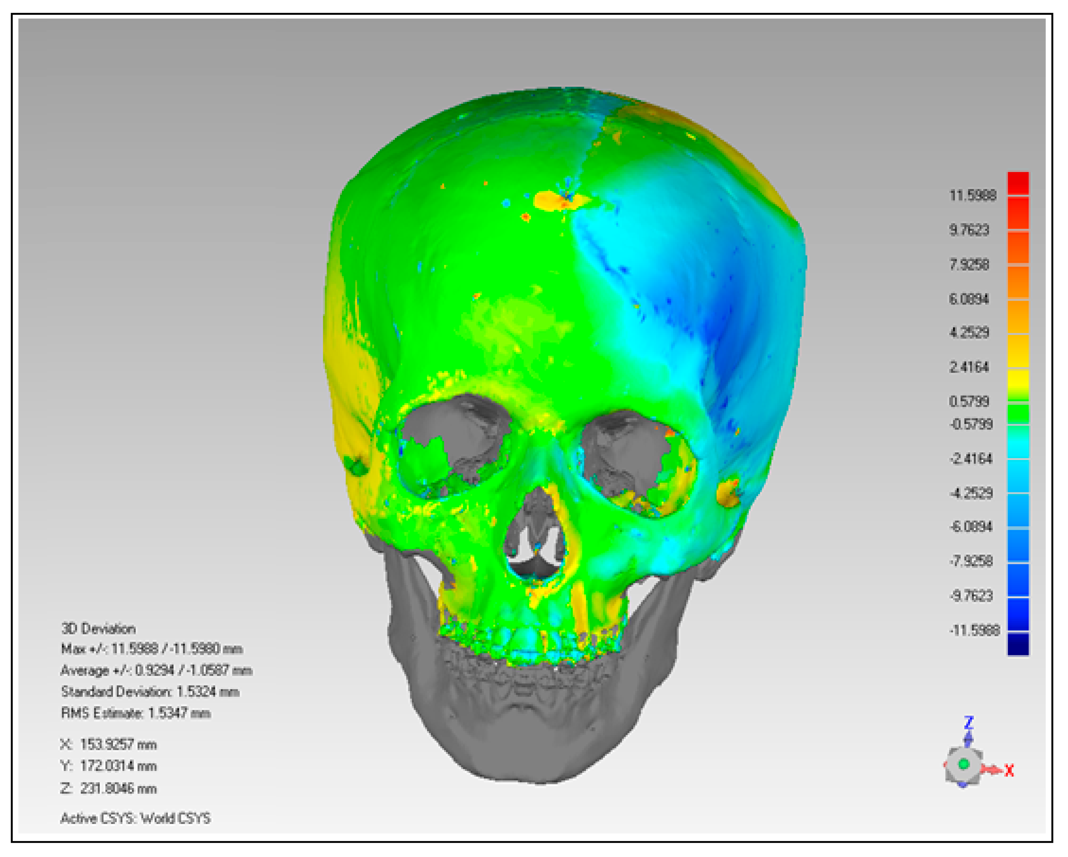
The outcome of the 3D deviation analysis has been represented graphically in
Figure 13. When the remodeled or reconstructed skull was analyzed with the mirrored cranium, the average deviation was in the range of 0.9294 mm in the outside direction and −1.0587 mm in the inward of the skull. Based on average deviation and RMS (1.5347 mm) values, the author inferred that the reconstructed skull was acceptable and it provided satisfactory aesthetics and appearance.
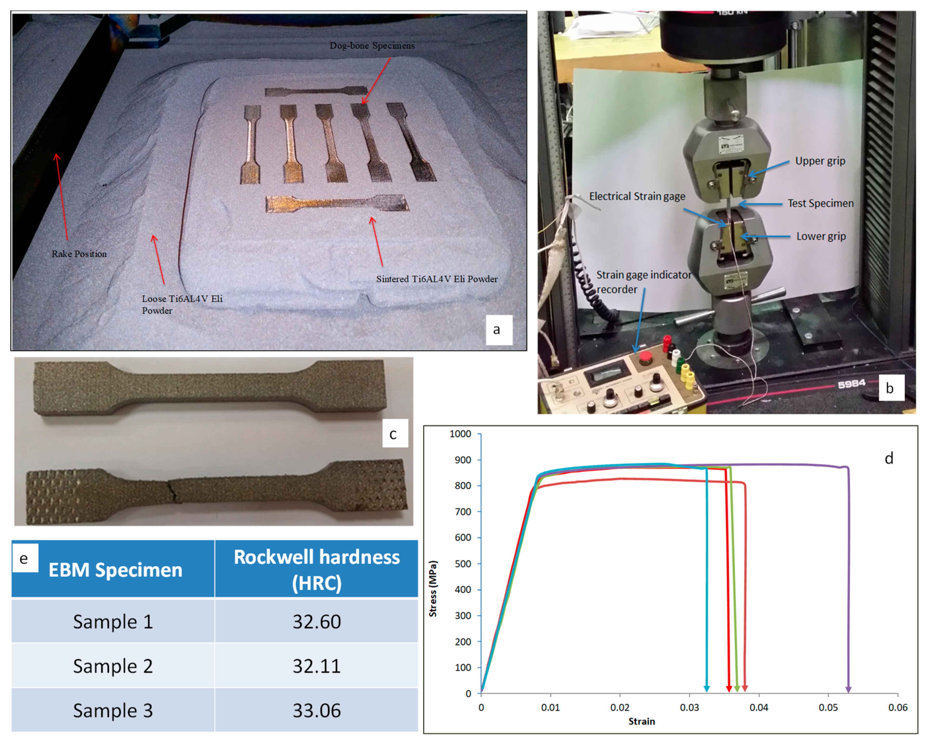
To analyze the tensile strength, the EBM produced dog bone specimens (n = 5) as shown in
Figure 14a were subjected to an axial tensile test. The tensile test was carried out using an Instron universal testing machine (5984 30 K, UTM-USA) as illustrated in
Figure 14b. The load and displacement data were regularly observed and noted. A constant displacement speed was maintained and its load and elongation were measured to test the tensile durability of the EBM built specimens. The strains were measured using strain gauge which was glued onto the specimens. The state-of-the-art built-in control platform Blue hill 3 was used to define, program, and perform the novel tests.
Figure 14c illustrates the EBM test samples before and after the tensile test. The stress-strain relationship of the EBM dog bone specimens was calculated and plotted as shown in
Figure 14d. The average yield and tensile strength of the specimens were determined from the stress-strain curves. The average yield and tensile strength for the EBM specimen were found to be 825 MPa and 880 MPa respectively from the tensile test. These values were better than the average yield (795 MPa) and tensile strength (860 MPa) required for Ti6Al4V ELI specimen [
33]. Moreover, these mechanical results were similar and in accordance with the values as reported by other researchers [
37,
50]. The calculated yield and tensile strength in the current study were higher than the required yield and tensile strength as per the ASTM standard [
33,
51]. This suggested that the EBM produced cranial implant possessed the required mechanical strength that is needed in medical applications.
Similarly, the surface hardness (or the resistance to deformation) of the EBM built specimen were determined by employing Rockwell hardness test (HRC) using WOLPERT UH930 (USA) universal hardness tester (
Figure S4). The Rockwell C scale is usually abbreviated HRC (Hardness Rockwell C). The indentation was generated using a cone diamond indenter with a load of 150 kgf (1.5 KN) for 3–5 s. Three arbitrary regions were identified on the top surface of three EBM built specimens and a mean value of nine measurements was computed for hardness. Each of the indentations was measured at a distance of 5 mm from the previous indentation. The surface hardness value of the Ti6Al4V ELI specimen was in the range of 30–35 HRC (
Figure 14e), which was consistent with the required ARCAM and ASTM standards [
33]. Notice that the computed values of strength and hardness can further be justified through multiple studies that have investigated the mechanical properties of EBM fabricated Ti6Al4V ELI specimen. Their studies also reported ultimate strength in the range of 775 to 1150 MPa and surface hardness in the range of 30 to 35 HRC [
52,
53].
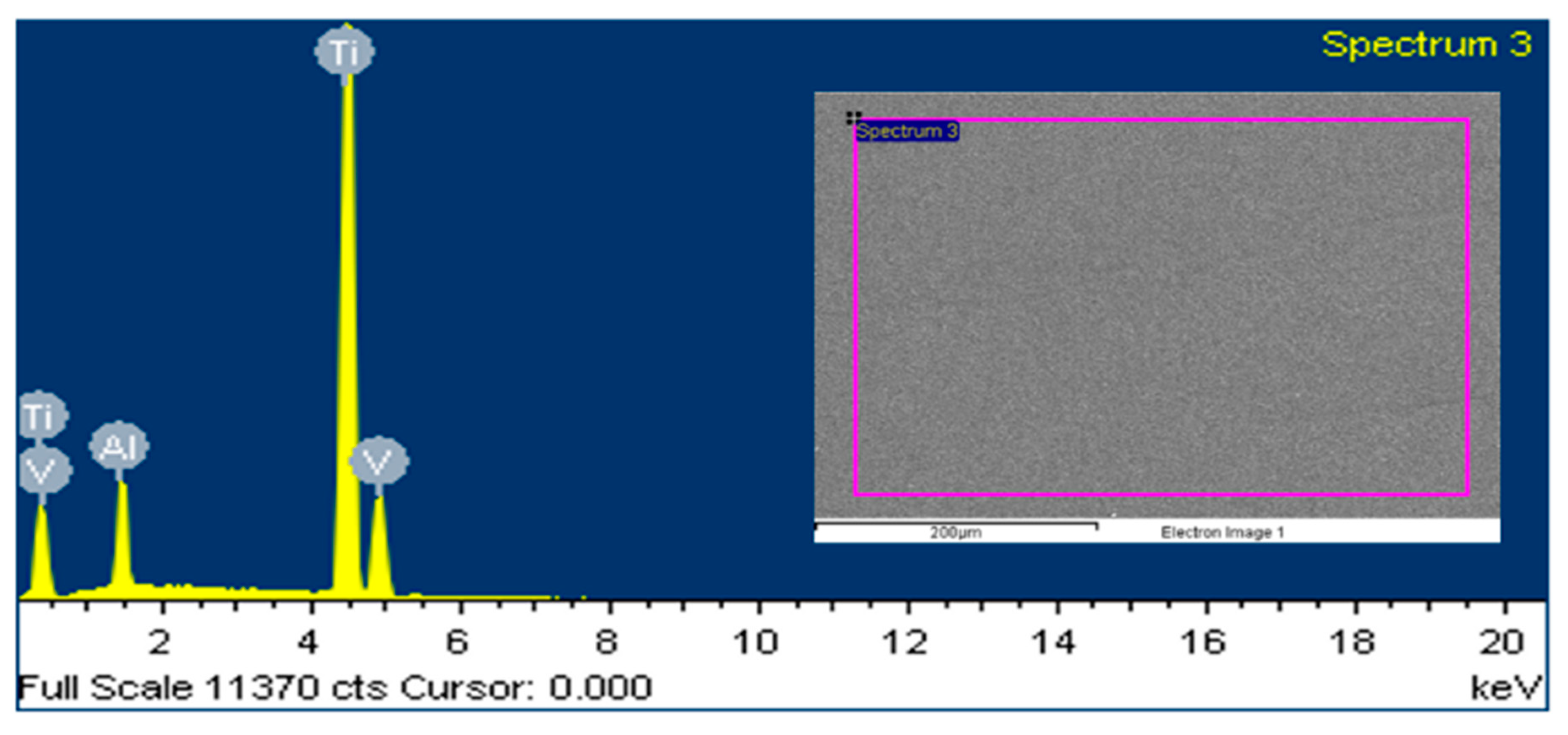
The consequent surface and elemental analysis of the EBM built specimen was also performed by employing JOEL JSM-6610LV SEM along with the attached energy dispersive X-ray spectroscopy (EDX). The EDX analysis was conducted to analyze the material composition in Ti6Al4V ELI post EBM fabrication. As shown in
Figure 15, the Ti peak was higher than the Al and V, as anticipated. The general composition of the specimen was measured as follows: 6.24% Al. 3.89% V and 89.87% Ti in weight percent. Based on the composition results, it can be inferred that the chemical composition of the fabricated EBM specimen did not vary considerably from the initial composition of the raw material (
Figure 9c).
To compute the weight of the substituted cranial bone, the density formulae were utilized in which volume was taken from the Magics
® software (Materialise, Belgium). The density was assumed to be 1600 kg/m
3 [
54]. The weights of the EBM fabricated titanium cranial implant was measured using a digital weighing scale. The results as shown in
Table 2 inferred that the weight of the EBM fabricated titanium cranial implant was a closer match to the substituted defected bone portion. Hence, EBM produced titanium implant will not have any stress shielding effect on the neighboring cranial bone tissue.
4. Conclusions
The realization of cranial reconstruction significantly depends on the restoration of its appearance, aesthetics and mechanical properties. It has been a known fact that the traditional methods of cranial reconstruction are insufficient because they cannot successfully address customization. Therefore, an effective methodology has been developed in the pursuit of a customized, pleasing and reliable cranial implant. The EBM technology has been integrated with CT to accomplish the objective of a customized implant. Certainly, the remarkable features of this methodology were its four pillars, including image processing, modeling, fabrication, and testing. Generally, the difficult task in customized reconstruction, especially using AM is the specification of its approval tests. Therefore, in this work, several validation techniques have been utilized to ascertain the quality of the implant produced by the EBM. For instance, the 3D comparison analysis was utilized to determine the accuracy and fitting of the implant, the tensile test was employed to confirm the mechanical strength, FEA to verify its load resistance ability, etc. The implemented approach was unique and exhaustive as it intended to minimize uncertainty in each phase through techniques such as STL error correction, thickness reduction, etc. The segmentation approach was employed to slice the defective region, while the mirror reconstruction technique was applied to acquire the customized implant for the affected region. The results of the 3D comparison analysis established that the anatomy or the outer profile of the skull were dependable in terms of appearance, fitting and aesthetics. The average deviation lied within the range of −1.0587 to 0.9294 mm, along with the RMS value of 1.5347 mm. These results also affirmed the mirror modeling technique as an ideal approach to reconstruct defects that exist on one side (left or right) of the head (imagine a plane running from head to tail leading to bilateral symmetry). Moreover, to minimize the shielding effect, the implant fabricated by the EBM was processed to achieve a thickness in the range of ≃1.76–2 mm. The FEA analysis was imperative to ascertain the loading ability of the designed customized implant. This analysis based on maximum stress (2.5 MPa), strain value (1.49 × 10⁻⁴) and maximum deformation (3.26 × 10⁻⁶ mm) deduced that the accomplished implant design can be employed convincingly in the restoration of the unhealthy skull region.
The analysis results post-fabrication were also adequate as acknowledged by various mechanical test procedures. The average yield (825 MPa) and the tensile strength (880 MPa) of the EBM fabricated specimens were in agreement with the previous researches as well as the ASTM standards in the medical industry. Similarly, the surface hardness of these specimens was in the range of 30–35 HRC, which was consistent with the desired ARCAM and ASTM norms. The chemical composition of the manufactured specimen also did not alter appreciably in comparison to its raw state, thus validating its intactness. Besides, the weight of the EBM fabricated titanium cranial implant was in complete agreement with that of the substituted skull region.
The employed approach is effective and useful because it can successfully minimize the revisions and errors, enhance fit and result in implant stability as well as reduce the treatment time and operative difficulties. The EBM produced cranial implant augments the aesthetic and functional recovery of cranium abnormalities to accomplish efficient and immediate reconstruction. The proposed method of custom designed cranial implant can be integrated with more facets of bone surgeries where reconstruction plates are applied. Certainly, the existing available techniques cannot confirm all of the growing customization needs, so attempts to develop a more appropriate mode of reconstruction should persist in the future. Therefore, the authors would like to extend this work by employing a new modeling technique and utilizing more tests, such as a fatigue test, validation of compressive strength, etc.


