A Feasibility Study of a Novel Piezo MEMS Tweezer for Soft Materials Characterization


Abstract
1. Introduction
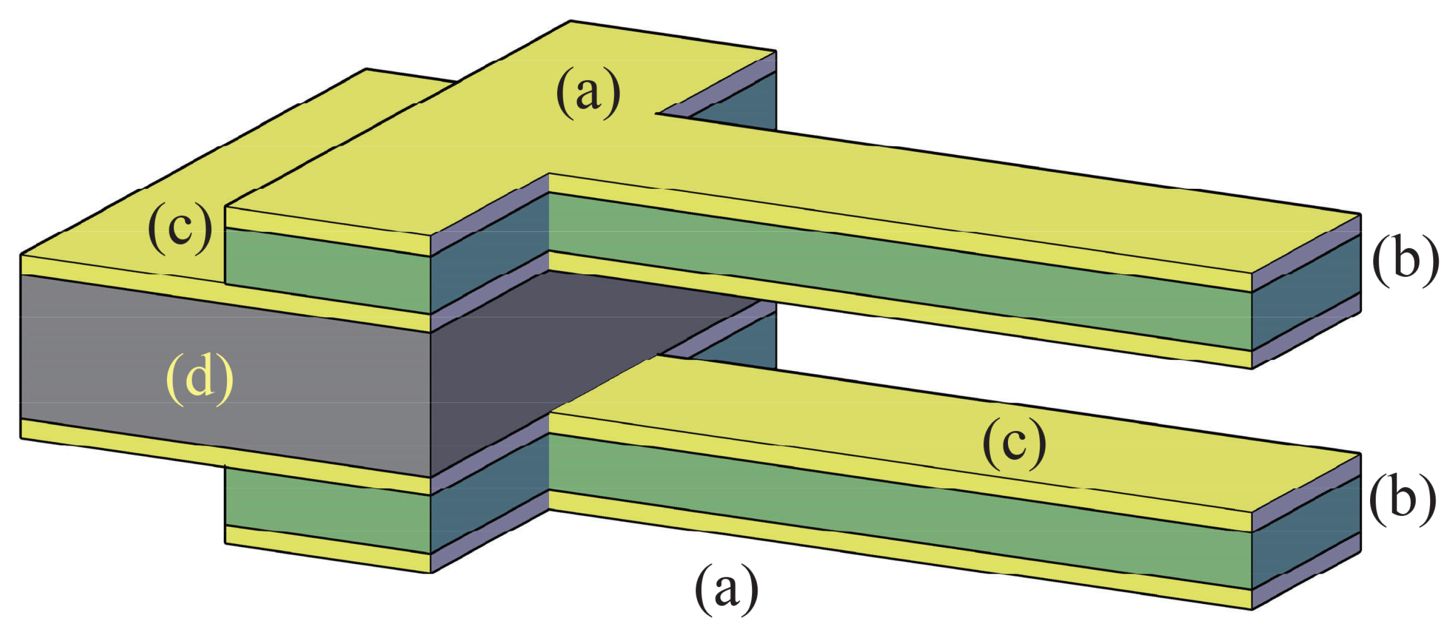
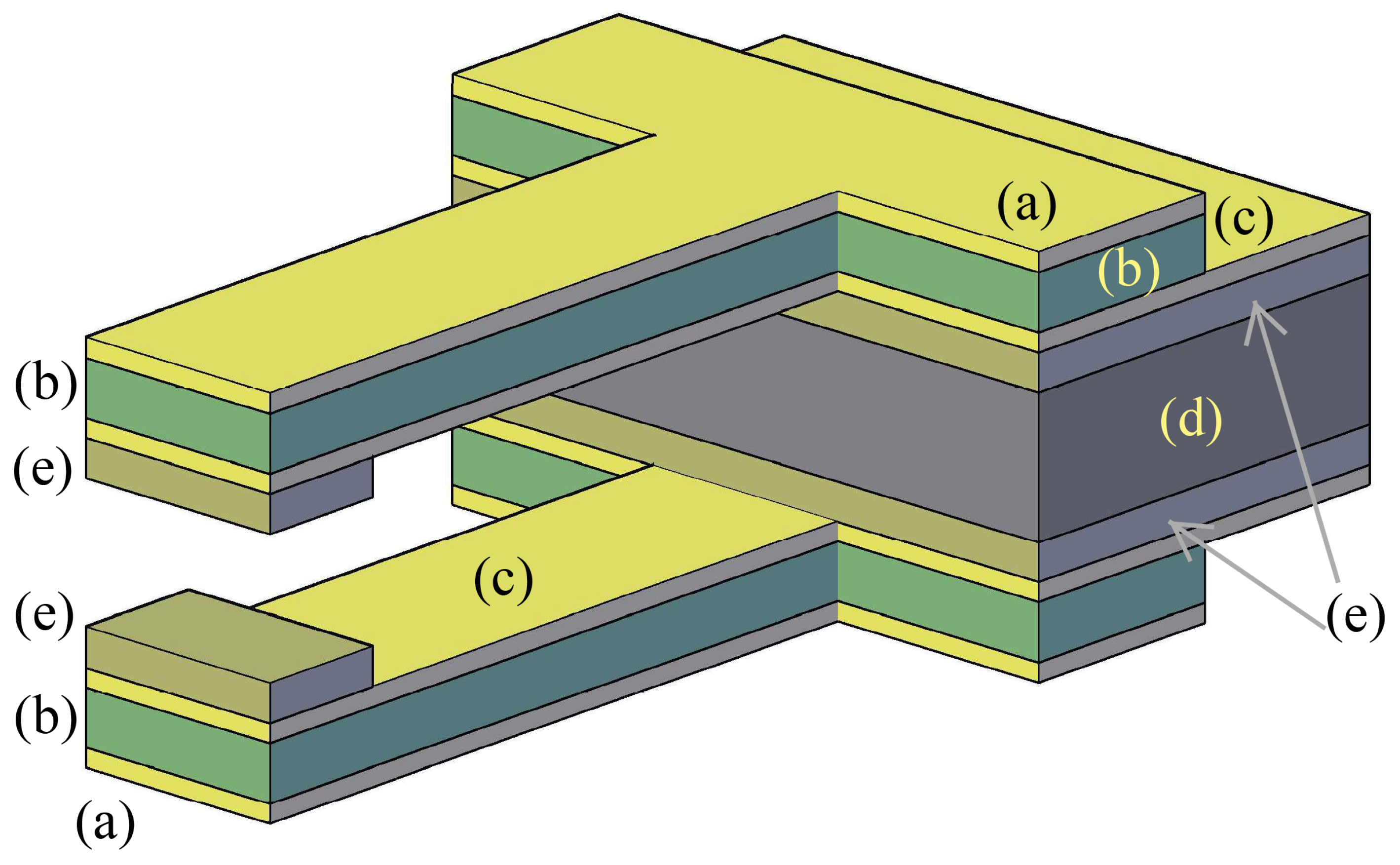
2. The Adopted Piezo-Mems Microgripper
- unimorph (one piezoelectric layer coupled with an inactive structural layer) or
- bimorph (a structural layer sandwiched by two active layers).
- pulsed laser deposition (PLD);
- chemical vapour deposition (CVD);
- screen printing;
- sol-gel and
- radio frequency sputtering.
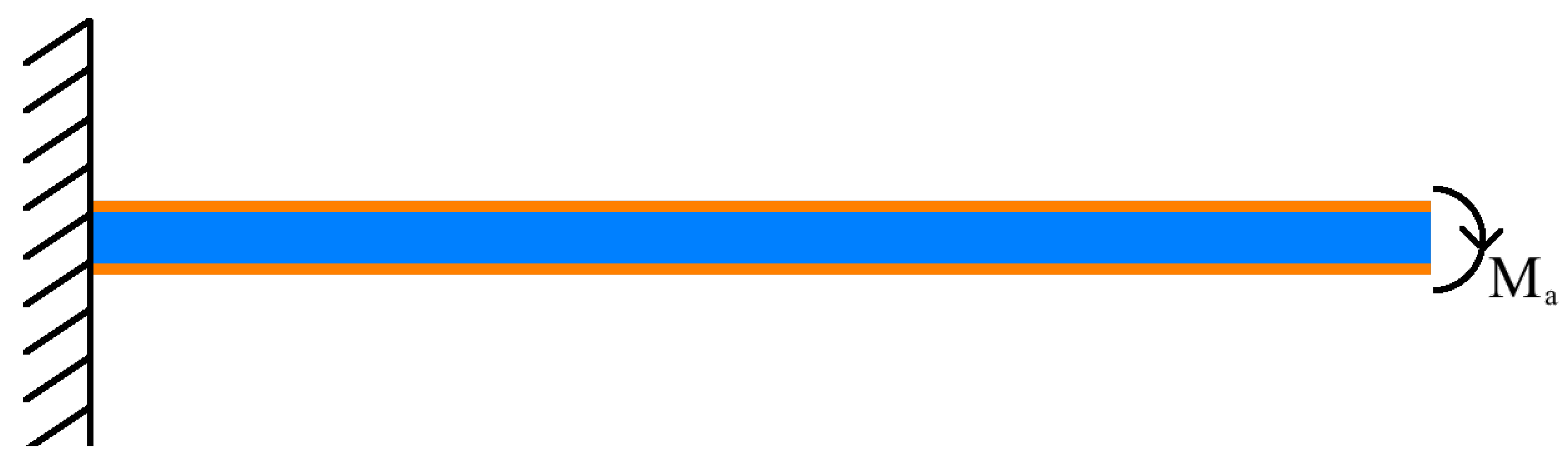
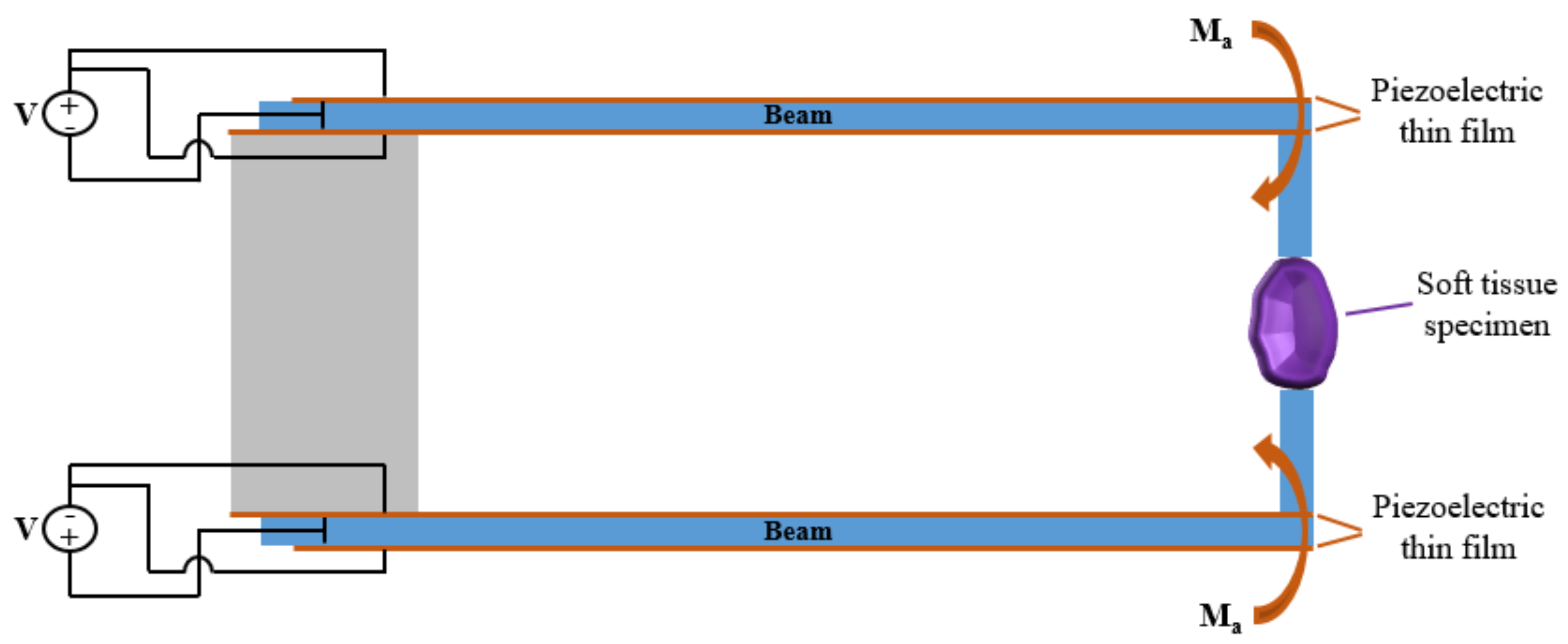
3. Modeling Piezoelectric Actions on the Microbeams
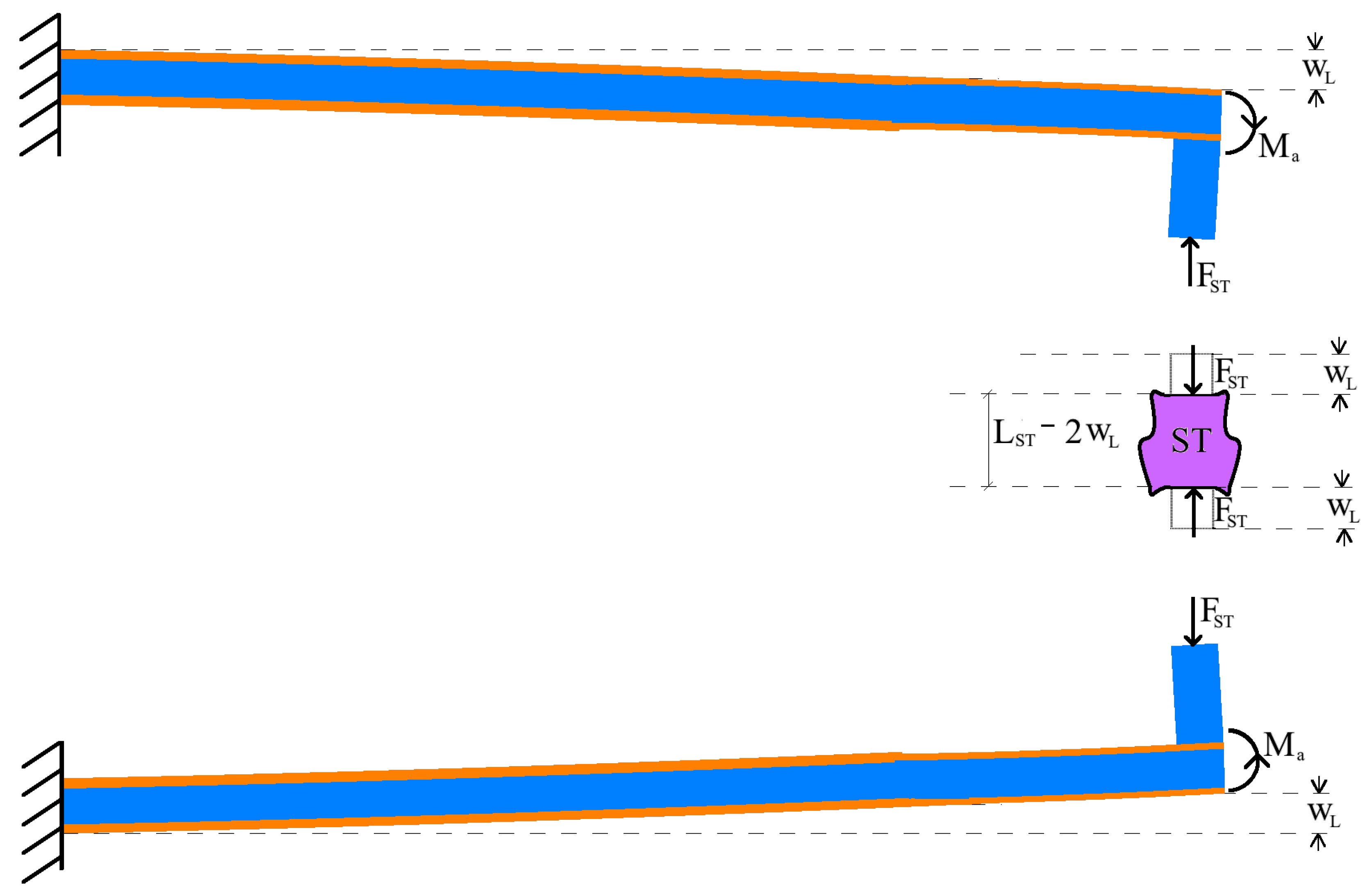
3.1. Static Model
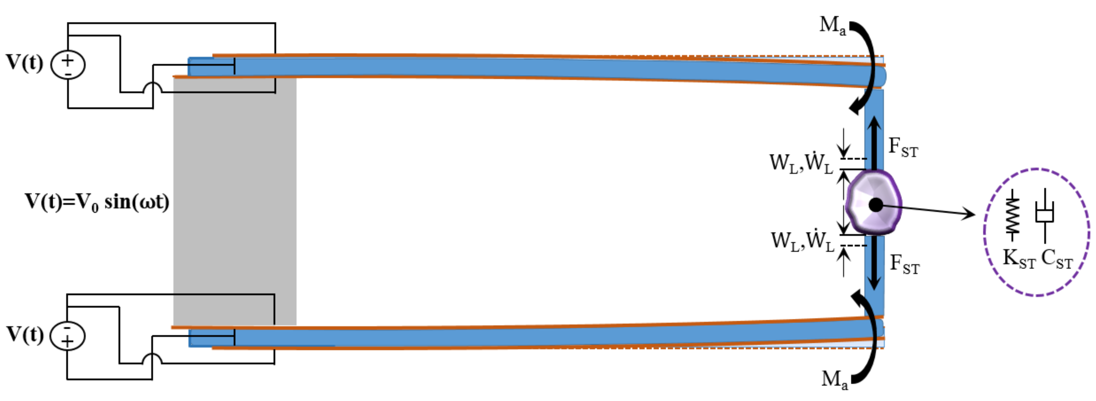
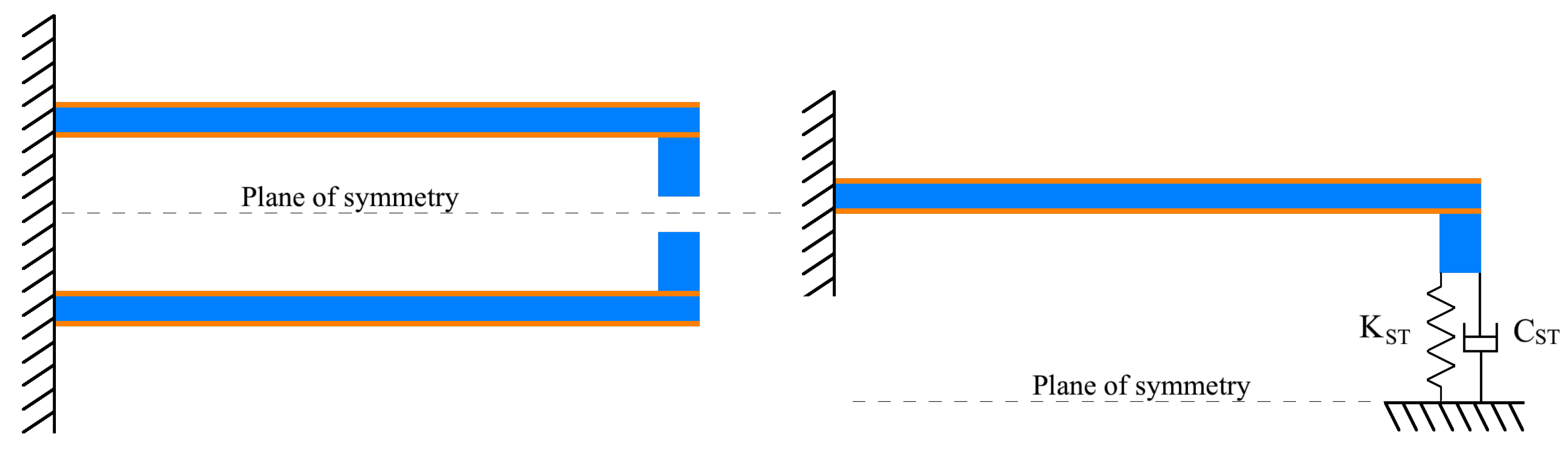
3.2. Dynamics Model
4. Results and Discussion
5. Conclusions
Author Contributions
Conflicts of Interest
Abbreviations
| C | damping coefficient |
| damping coefficient of the soft tissue | |
| piezoelectric coefficient | |
| Young’s modulus of the piezoelectric material | |
| Young’s modulus of the beam | |
| equivalent Young’s modulus of the soft tissue | |
| force applied from the soft tissue to the tweezers | |
| inertia moment of the beam | |
| K | stiffness coefficient |
| stiffness coefficient of the soft tissue | |
| L | beam length |
| m | mass applied at the end of the tweezer |
| piezoelectric bending moment | |
| M | mass coefficient |
| cross-sectional area of the soft tissue | |
| soft tissue | |
| piezoelectric thickness | |
| beam thickness | |
| V | electric potential applied to the piezoelectric plates |
| w | transverse displacement |
| transverse displacement of the free end | |
| virtual transverse displacement | |
| i-th flexural mode of the beam | |
| mass density of the beam | |
| natural frequency of the i-th flexural mode |
References
- Tang, M.; Xia, L.; Wei, D.; Yan, S.; Du, C.; Cui, H.L. Distinguishing Different Cancerous Human Cells by Raman Spectroscopy Based on Discriminant Analysis Methods. Appl. Sci. 2017, 7, 900. [Google Scholar] [CrossRef]
- Rianna, C.; Radmacher, M. Comparison of viscoelastic properties of cancer and normal thyroid cells on different stiffness substrates. Eur. Biophys. J. 2017, 46, 309–324. [Google Scholar] [CrossRef] [PubMed]
- Lekka, M.; Gil, D.; Pogoda, K.; Dulińska-Litewka, J.; Jach, R.; Gostek, J.; Klymenko, O.; Prauzner-Bechcicki, S.; Stachura, Z.; Wiltowska-Zuber, J.; et al. Cancer cell detection in tissue sections using AFM. Arch. Biochem. Biophys. 2012, 518, 151–156. [Google Scholar] [CrossRef] [PubMed]
- Discher, D.E.; Boal, D.H.; Boey, S.K. Simulations of the erythrocyte cytoskeleton at large deformation. II. Micropipette aspiration. Biophys. J. 1998, 75, 1584–1597. [Google Scholar] [CrossRef]
- Bausch, A.R.; Ziemann, F.; Boulbitch, A.A.; Jacobson, K.; Sackmann, E. Local measurements of viscoelastic parameters of adherent cell surfaces by magnetic bead microrheometry. Biophys. J. 1998, 75, 2038–2049. [Google Scholar] [CrossRef]
- Weisenhorn, A.L.; Khorsandi, M.; Kasas, S.; Gotzos, V.; Butt, H.J. Deformation and height anomaly of soft surfaces studied with an AFM. Nanotechnology 1993, 4, 106. [Google Scholar] [CrossRef]
- Guck, J.; Ananthakrishnan, R.; Cunningham, C.C.; Käs, J. Stretching biological cells with light. J. Phys. Condens. Matter 2002, 14, 4843. [Google Scholar] [CrossRef]
- Adldoost, H.; Jouibary, B.R.; Zabihollah, A. Design of SMA micro-gripper for minimally invasive surgery. In Proceedings of the 2012 19th Iranian Conference of Biomedical Engineering, Tehran, Iran, 20–21 December 2012. [Google Scholar]
- Botta, F.; Verotti, M.; Bagolini, A.; Bellutti, P.; Belfiore, N.P. Mechanical response of four-bar linkage microgrippers with bidirectional electrostatic actuation. Actuators 2018, 7, 78. [Google Scholar] [CrossRef]
- Tsai, Y.C.; Lei, S.H.; Sudin, H. Design and analysis of planar compliant microgripper based on kinematic approach. J. Micromech. Microeng. 2004, 15, 143. [Google Scholar] [CrossRef]
- Wierzbicki, R.; Adda, C.; Hotzendorfer, H. Electrostatic silicon microgripper with low voltage of actuation. In Proceedings of the 2007 International Symposium on Micro-NanoMechatronics and Human Science, Nagoya, Japan, 11–14 November 2007. [Google Scholar]
- Hamedi, M.; Salimi, P.; Vismeh, M. Simulation and experimental investigation of a novel electrostatic microgripper system. Microelectron. Eng. 2012, 98, 467–471. [Google Scholar] [CrossRef]
- Piriyanont, B.; Moheimani, S.R.; Bazaei, A. Design and control of a MEMS micro-gripper with integrated electro-thermal force sensor. In Proceedings of the 2013 Australian Control Conference, Fremantle, WA, Australia, 4–5 November 2013. [Google Scholar]
- Wierzbicki, R.; Houston, K.; Heerlein, H.; Barth, W.; Debski, T.; Eisinberg, A.; Dario, P. Design and fabrication of an electrostatically driven microgripper for blood vessel manipulation. Microelectron. Eng. 2006, 83, 1651–1654. [Google Scholar] [CrossRef]
- Zhang, Y.; Chen, B.K.; Liu, X.; Sun, Y. Autonomous robotic pick-and-place of microobjects. IEEE Trans. Robot. 2010, 26, 200–207. [Google Scholar] [CrossRef]
- Scalari, G.; Eisinberg, A.; Mazzoni, M.; Menciassi, A.; Dario, P. A sensorized μelectro discharge machined superelastic alloy microgripper for micromanipulation. In Proceedings of the IEEE/RSJ International Conference on Intelligent Robots and Systems, Lausanne, Switzerland, 30 September–4 October 2002; pp. 1591–1595. [Google Scholar]
- Greminger, M.A.; Sezen, A.S.; Nelson, B.J. A four degree of freedom MEMS microgripper with novel bi-directional thermal actuators. In Proceedings of the 2005 IEEE/RSJ International Conference on Intelligent Robots and Systems, Edmonton, AB, Canada, 2–6 August 2005. [Google Scholar]
- Chang, R.J.; Chen, C.C. Using microgripper for adhesive bonding in automatic microassembly system. In Proceedings of the International Conference on Mechatronics and Automation, Harbin, China, 5–8 August 2007. [Google Scholar]
- Chronis, N.; Lee, L.P. Polymer MEMS-based microgripper for single cell manipulation. In Proceedings of the 17th IEEE International Conference on Micro Electro Mechanical Systems. Maastricht MEMS 2004 Technical Digest, Maastricht, The Netherlands, 25–29 January 2004. [Google Scholar]
- Sun, X.; Chen, W.; Fatikow, S.; Tian, Y.; Zhou, R.; Zhang, J.; Mikczinski, M. A novel piezo-driven microgripper with a large jaw displacement. Microsyst. Technol. 2015, 21, 931–942. [Google Scholar] [CrossRef]
- Belfiore, N.P.; Broggiato, G.B.; Verotti, M.; Balucani, M.; Crescenzi, R.; Bagolini, A.; Bellutti, P.; Boscardin, M. Simulation and construction of a mems CSFH based microgripper. Int. J. Mech. Control 2015, 16, 21–30. [Google Scholar]
- Verotti, M.; Crescenzi, R.; Balucani, M.; Belfiore, N.P. MEMS-based conjugate surfaces flexure hinge. J. Mech. Des. 2015, 137, 012301. [Google Scholar] [CrossRef]
- Cecchi, R.; Verotti, M.; Capata, R.; Dochshanov, A.; Broggiato, G.; Crescenzi, R.; Balucani, M.; Natali, S.; Razzano, G.; Lucchese, F.; et al. Development of micro-grippers for tissue and cell manipulation with direct morphological comparison. Micromachines 2015, 6, 1710–1728. [Google Scholar] [CrossRef]
- Verotti, M.; Dochshanov, A.; Belfiore, N.P. Compliance Synthesis of CSFH MEMS-Based Microgrippers. J. Mech. Des. 2017, 139. [Google Scholar] [CrossRef]
- Crescenzi, R.; Balucani, M.; Belfiore, N.P. Operational characterization of CSFH MEMS technology based hinges. J. Micromech. Microeng. 2018, 28, 055012. [Google Scholar] [CrossRef]
- Verotti, M. Analysis of the center of rotation in primitive flexures: Uniform cantilever beams with constant curvature. Mech. Mach. Theory 2016, 97, 29–50. [Google Scholar] [CrossRef]
- Verotti, M. Effect of initial curvature in uniform flexures on position accuracy. Mech. Mach. Theory 2018, 119, 106–118. [Google Scholar] [CrossRef]
- Di Giamberardino, P.; Bagolini, A.; Bellutti, P.; Rudas, I.; Verotti, M.; Botta, F.; Belfiore, N.P. New MEMS tweezers for the viscoelastic characterization of soft materials at the microscale. Micromachines 2018, 9, 15. [Google Scholar] [CrossRef] [PubMed]
- Ursi, P.; Santoro, A.; Gemini, A.; Arezzo, A.; Pironi, D.; Renzi, C.; Cirocchi, R.; Di Matteo, F.; Maturo, A.; D’Andrea, V.; et al. Comparison of outcomes following intersphincteric resection vs low anterior resection for low rectal cancer: A systematic review. G. Di Chir. 2018, 39, 123–142. [Google Scholar]
- Balla, A.; Quaresima, S.; Ursi, P.; Seitaj, A.; Palmieri, L.; Badiali, D.; Paganini, A.M. Hiatoplasty with crura buttressing versus hiatoplasty alone during laparoscopic sleeve gastrectomy. Gastroenterol. Res. Pract. 2017, 2017. [Google Scholar] [CrossRef] [PubMed]
- Cochetti, G.; Del Zingaro, M.; Boni, A.; Cocca, D.; Panciarola, M.; Tiezzi, A.; Gaudio, G.; Balzarini, F.; Ursi, P.; Mearini, E. Colovesical fistula: Review on conservative management, surgical techniques and minimally invasive approaches. G. Di Chir. 2018, 39, 195–207. [Google Scholar]
- Popivanov, G.; Tabakov, M.; Mantese, G.; Cirocchi, R.; Piccinini, I.; D’Andrea, V.; Covarelli, P.; Boselli, C.; Barberini, F.; Tabola, R.; et al. Surgical treatment of gastrointestinal stromal tumors of the duodenum: A literature review. Transl. Gastroenterol. Hepatol. 2018, 3. [Google Scholar] [CrossRef] [PubMed]
- Paci, M.; Scoglio, D.; Ursi, P.; Barchetti, L.; Fabiani, B.; Ascoli, G.; Lezoche, G. Transanal Endocopic Microsurgery (TEM) in advanced rectal cancer disease treatment [Il ruolo della TEM nel trattamento dei tumori del retto extraperitoneale]. Ann. Ital. Di Chir. 2010, 81, 269–274. [Google Scholar]
- Quaresima, S.; Balla, A.; Dambrosio, G.; Bruzzone, P.; Ursi, P.; Lezoche, E.; Paganini, A.M. Endoluminal loco-regional resection by TEM after R1 endoscopic removal or recurrence of rectal tumors. Minim. Invasive Ther. Allied Technol. 2016, 25, 134–140. [Google Scholar] [CrossRef]
- Lezoche, E.; Fabiani, B.; D’Ambrosio, G.; Ursi, P.; Balla, A.; Lezoche, G.; Monteleone, F.; Paganini, A.M. Nucleotide-guided mesorectal excision combined with endoluminal locoregional resection by transanal endoscopic microsurgery in the treatment of rectal tumors: Technique and preliminary results. Surg. Endosc. 2013, 27, 4136–4141. [Google Scholar] [CrossRef]
- Legtenberg, R.; Groeneveld, A.W.; Elwenspoek, M. Comb-drive actuators for large displacements. J. Micromech. Microeng. 1996, 6, 320. [Google Scholar] [CrossRef]
- Chen, T.; Sun, L.; Chen, L.; Rong, W.; Li, X. A hybrid-type electrostatically driven microgripper with an integrated vacuum tool. Sens. Actuators A Phys. 2010, 158, 320–327. [Google Scholar] [CrossRef]
- Yeh, J.A.; Chen, C.N.; Lui, Y.S. Large rotation actuated by in-plane rotary comb-drives with serpentine spring suspension. J. Micromech. Microeng. 2004, 15, 201. [Google Scholar] [CrossRef]
- Yeh, J.A.; Jiang, S.S.; Lee, C. MOEMS variable optical attenuators using rotary comb drive actuators. IEEE Photonics Technol. Lett. 2006, 18, 1170–1172. [Google Scholar] [CrossRef]
- Kim, K.; Liu, X.; Zhang, Y.; Sun, Y. Nanonewton force-controlled manipulation of biological cells using a monolithic MEMS microgripper with two-axis force feedback. J. Micromech. Microeng. 2008, 18. [Google Scholar] [CrossRef]
- Kim, K.; Liu, X.; Zhang, Y.; Cheng, J.; Wu, X.Y.; Sun, Y. Elastic and viscoelastic characterization of microcapsules for drug delivery using a force-feedback MEMS microgripper. Biomed. Microdevices 2009, 11, 421–427. [Google Scholar] [CrossRef]
- Solano, B.; Wood, D. Design and testing of a polymeric microgripper for cell manipulation. Microelectron. Eng. 2007, 84, 1219–1222. [Google Scholar] [CrossRef]
- Zeman, M.J.; Bordatchev, E.V.; Knopf, G.K. Design, kinematic modeling and performance testing of an electro-thermally driven microgripper for micromanipulation applications. J. Micromech. Microeng. 2006, 16, 1540. [Google Scholar] [CrossRef]
- Zhang, R.; Chu, J.; Wang, H.; Chen, Z. A multipurpose electrothermal microgripper for biological micro-manipulation. Microsyst. Technol. 2013, 19, 89–97. [Google Scholar] [CrossRef]
- Cauchi, M.; Grech, I.; Mallia, B.; Mollicone, P.; Sammut, N. The effects of cold arm width and metal deposition on the performance of a U-beam electrothermal MEMS microgripper for biomedical applications. Micromachines 2019, 10, 167. [Google Scholar] [CrossRef]
- Cauchi, M.; Grech, I.; Mallia, B.; Mollicone, P.; Sammut, N. The effects of structure thickness, air gap thickness and silicon type on the performance of a horizontal electrothermal MEMS microgripper. Actuators 2018, 7, 38. [Google Scholar] [CrossRef]
- Ren, H.; Wu, S.T. Adaptive Lenses Based on Soft Electroactive Materials. Appl. Sci. 2018, 8, 1085. [Google Scholar] [CrossRef]
- Yan, B.; Wang, K.; Hu, Z.; Wu, C.; Zhang, X. Shunt damping vibration control technology: A review. Appl. Sci. 2017, 7, 494. [Google Scholar] [CrossRef]
- Rossi, A.; Orsini, F.; Scorza, A.; Botta, F.; Belfiore, N.P.; Sciuto, S.A. A review on parametric dynamic models of magnetorheological dampers and their characterization methods. Actuators 2018, 7, 16. [Google Scholar] [CrossRef]
- Botta, F.; Marx, N.; Gentili, S.; Schwingshackl, C.W.; Di Mare, L.; Cerri, G.; Dini, D. Optimal placement of piezoelectric plates for active vibration control of gas turbine blades: Experimental results. In Proceedings of the SPIE - The International Society for Optical Engineering, San Diego, CA, USA, 11–15 March 2012; Volume 8345. [Google Scholar]
- Botta, F.; Dini, D.; Schwingshackl, C.; Di Mare, L.; Cerri, G. Optimal placement of piezoelectric plates to control multimode vibrations of a beam. Adv. Acoustics Vib. 2013. [Google Scholar] [CrossRef]
- Botta, F.; Rossi, A.; Schinaia, L.; Scorza, A.; Orsini, F.; Sciuto, S.A.; Belfiore, N.P. Experimental validation on optimal placement of pzt plates for active beam multimode vibrations reduction. In Proceedings of the 23rd Conference of the Italian Association of Theoretical and Applied Mechanics AIMETA 2017, Salerno, Italy, 4–7 September 2017; Volume 3, pp. 2258–2269. [Google Scholar]
- Botta, F.; Toccaceli, F. Piezoelectric plates distribution for active control of torsional vibrations. Actuators 2018, 7, 23. [Google Scholar] [CrossRef]
- Xiao, Y.; Wang, B.; Zhou, S. Pull-in voltage analysis of electrostatically actuated MEMS with piezoelectric layers: A size-dependent model. Mech. Res. Commun. 2015, 66, 7–14. [Google Scholar] [CrossRef]
- Azizi, S.; Ghodsi, A.; Jafari, H.; Ghazavi, M.R. A conceptual study on the dynamics of a piezoelectric MEMS (Micro Electro Mechanical System) energy harvester. Energy 2016, 96, 495–506. [Google Scholar] [CrossRef]
- Madinei, H.; Khodaparast, H.H.; Adhikari, S.; Friswell, M.I.; Fazeli, M. Adaptive tuned piezoelectric MEMS vibration energy harvester using an electrostatic device. Eur. Phys. J. Spec. Top. 2015, 224, 2703–2717. [Google Scholar] [CrossRef]
- Kanno, I. Piezoelectric MEMS for energy harvesting. J. Phys. Conf. Ser. 2015, 660. [Google Scholar] [CrossRef]
- Tian, W.; Ling, Z.; Yu, W.; Shi, J. A review of MEMS scale piezoelectric energy harvester. Appl. Sci. 2018, 8, 645. [Google Scholar] [CrossRef]
- Nah, S.K.; Zhong, Z.W. A microgripper using piezoelectric actuation for micro-object manipulation. Sens. Actuators A Phys. 2007, 133, 218–224. [Google Scholar] [CrossRef]
- Haddab, Y.; Chaillet, N.; Bourjault, A. A microgripper using smart piezoelectric actuators. In Proceedings of the 2000 IEEE/RSJ International Conference on Intelligent Robots and Systems, Takamatsu, Japan, 31 October–5 November 2000; Volume 1. [Google Scholar]
- Wang, D.H.; Yang, Q.; Dong, H.M. A monolithic compliant piezoelectric-driven microgripper: Design, modeling, and testing. IEEE/ASME Trans. Mechatron. 2013, 18, 138–147. [Google Scholar] [CrossRef]
- Loh, O.; Vaziri, A.; Espinosa, H.D. The potential of MEMS for advancing experiments and modeling in cell mechanics. Exp. Mech. 2009, 49, 105–124. [Google Scholar] [CrossRef]
- Crawley, E.F.; Luis, J.D. Use of piezoelectric actuators as elements of intelligent structures. AIAA J. 1987, 25, 1373–1385. [Google Scholar] [CrossRef]
- Eom, C.B.; Trolier-McKinstry, S. Thin-film piezoelectric MEMS. MRS Bull. 2012, 37, 1007–1017. [Google Scholar] [CrossRef]
- Xu, R.; Lei, A.; Christiansen, T.L.; Hansen, K.; Guizzetti, M.; Birkelund, K.; Thomsen, E.V.; Hansen, O. Screen printed PZT/PZT thick film bimorph MEMS cantilever device for vibration energy harvesting. In Proceedings of the 2011 16th International Solid-State Sensors, Actuators and Microsystems Conference, TRANSDUCERS’11, Beijing, China, 5–9 June 2011; pp. 679–682. [Google Scholar]
- Shen, D.; Park, J.H.; Ajitsaria, J.; Choe, S.Y.; Wikle, H.C.; Kim, D.J. The design, fabrication and evaluation of a MEMS PZT cantilever with an integrated Si proof mass for vibration energy harvesting. J. Micromech. Microeng. 2008, 18, 055017. [Google Scholar] [CrossRef]
- Mayrhofer, P.M.; Wistrela, E.; Kucera, M.; Bittner, A.; Schmid, U. Fabrication and characterisation of ScAlN-based piezoelectric MEMS cantilevers. In Proceedings of the 2015 Transducers—2015 18th International Conference on Solid-State Sensors, Actuators and Microsystems, TRANSDUCERS 2015, Anchorage, AK, USA, 21–25 June 2015; pp. 2144–2147. [Google Scholar]
- Nagano, T.; Nishigaki, M.; Abe, K.; Itaya, K.; Kawakubo, T. Fabrication and performance of piezoelectric MEMS tunable capacitors constructed with AlN bimorph structure. In Proceedings of the IEEE MTT-S International Microwave Symposium Digest, San Francisco, CA, USA, 11–16 June 2006; pp. 1285–1288. [Google Scholar]
- Park, J.S.; Yang, S.J.; Kyung-Il, L.E.E.; Kang, S.G. Fabrication and electro-mechanical characteristics of piezoelectric micro bending actuators on silicon substrates. J. Ceram. Soc. Jpn. 2006, 114, 1089–1092. [Google Scholar] [CrossRef][Green Version]
- Yuan, Y.H.; Du, H.J.; Xia, X.; Wong, Y.R. Modeling, fabrication and characterization of piezoelectric ZnO-based micro-sensors and micro-actuators. Appl. Mech. Mater. 2014, 444–445, 1636–1643. [Google Scholar] [CrossRef]
- Lou, L.; Yu, H.; Haw, M.T.X.; Zhang, S.; Gu, Y.A. Comparative characterization of bimorph and unimorph AlN piezoelectric micro-machined ultrasonic transducers. In Proceedings of the IEEE International Conference on Micro Electro Mechanical Systems (MEMS), Shanghai, China, 24–28 January 2016; Volume 2016-February. pp. 1090–1093. [Google Scholar]
- Zeng, Y.; Groenesteijn, J.; Alveringh, D.; Steenwelle, R.J.A.; Ma, K.; Wiegerink, R.J.; Lotters, J.C. Micro Coriolis MASS flow sensor driven by integrated PZT thin film actuators. In Proceedings of the IEEE International Conference on Micro Electro Mechanical Systems (MEMS), Belfast, UK, 21–25 January 2018; Volume 2018-January. pp. 850–853. [Google Scholar]
- Sindhanaiselvi, D.; Shanmuganantham, T. Investigation on performance of piezoelectric beam based MEMS actuator for focussing of micro lens in mobile application. In Proceedings of the IEEE International Conference on Circuits and Systems, ICCS 2017, Thiruvananthapuram, India, 20–21 December 2017; Volume 2018-January. pp. 398–403. [Google Scholar]
- Chen, S.H.; Michael, A.; Kwok, C.Y. A Fast Response MEMS Piezoelectric Microlens Actuator with Large Stroke and Low Driving Voltage. In Proceedings of the NEMS 2018 - 3th Annual IEEE International Conference on Nano/Micro Engineered and Molecular Systems, Singapore, Singapore, 22–26 April 2018; pp. 199–203. [Google Scholar]
- Tsaur, J.; Zhang, L.; Maeda, R.; Matsumoto, S.; Khumpuang, S.; Wan, J. Design and fabrication of 1D and 2D micro scanners actuated by double layered PZT bimorph beams. In Proceedings of the 2001 International Microprocesses and Nanotechnology Conference, MNC 2001, Shimane, Japan, 31 October–2 November 2001; pp. 204–205. [Google Scholar]
- Tsaur, J.; Zhang, L.; Maeda, R.; Matsumoto, S.; Khumpuang, S. Design and Fabrication of 1D and 2D Micro Scanners Actuated by Double Layered Lead Zirconate Titanate (PZT) Bimorph Beams. Jpn. J. Appl. Phys. 2002, 41, 4321–4326. [Google Scholar] [CrossRef]
- Kuo, C.L.; Lin, S.C.; Wu, W.J. Fabrication and performance evaluation of a metal-based bimorph piezoelectric MEMS generator for vibration energy harvesting. Smart Mater. Struct. 2016, 25, 1280–1284. [Google Scholar] [CrossRef]
- Che, L.; Halvorsen, E.; Chen, X.; Yan, X. A micromachined piezoelectric PZT-based cantilever in d33 mode. In Proceedings of the 2010 IEEE 5th International Conference on Nano/Micro Engineered and Molecular Systems, NEMS 2010, Xiamen, China, 20–23 January 2010; pp. 785–788. [Google Scholar]
- Kanno, I. Piezoelectric MEMS: Ferroelectric thin films for MEMS applications. Jpn. J. Appl. Phys. 2018, 57. [Google Scholar] [CrossRef]
- Strambi, G.; Barboni, R.; Gaudenzi, P. Pin-force and Euler-Bernoulli models for analysis of intelligent structures. AIAA J. 1995, 33, 1746–1749. [Google Scholar] [CrossRef]
- Waisman, H.; Abramovich, H. Active stiffening of laminated composite beams using piezoelectric actuators. Compos. Struct. 2002, 58, 109–120. [Google Scholar] [CrossRef]
- Botta, F.; Scorza, A.; Rossi, A. Optimal piezoelectric potential distribution for controlling multimode vibrations. Appl. Sci. 2018, 8, 551. [Google Scholar] [CrossRef]
- Wells, P.N.; Liang, H.D. Medical ultrasound: Imaging of soft tissue strain and elasticity. J. R. Soc. Interface 2011, 8, 1521–1549. [Google Scholar] [CrossRef]


| Material | Length | Thickness | Width | Young’s mod. [GPa] | Density | |
|---|---|---|---|---|---|---|
| Beams | Silicon | 750 | 2 | 80 | 170 | 2329 |
| Piezoel. pl. | AlN | 750 | 80 | 350 | 3300 | |
| Clamp teeth | Silicon | 36 | 7.5 | 80 | 170 | 2329 |
| E [kPa] | [kPa] | ||
|---|---|---|---|
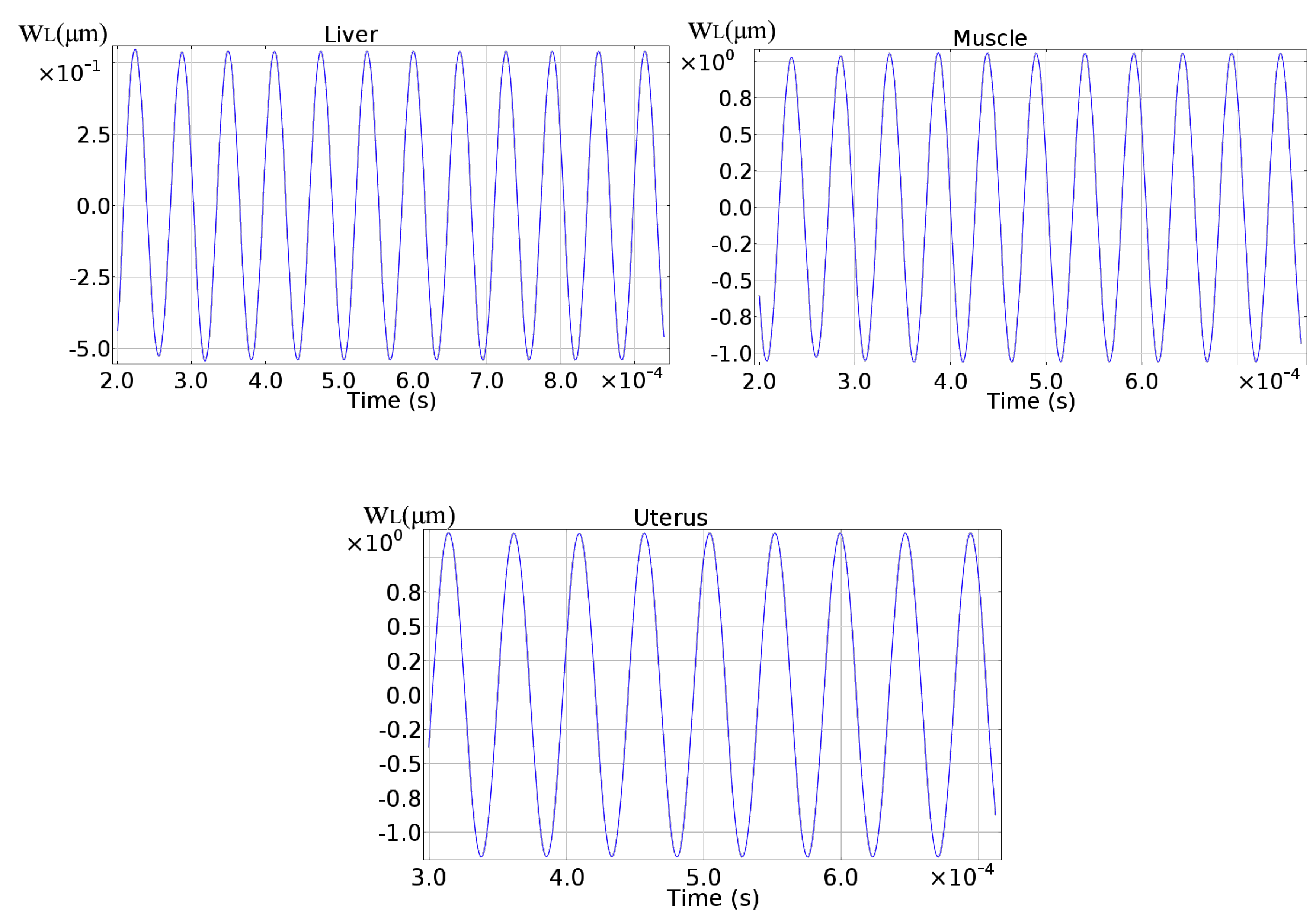
| Liver | 10 | 9.47 | |
| Muscle | 20 | 19.43 | |
| Uterus | 30 | 29.64 | 1.2% |
| Liver | |||
| 15,856.40 | |||
| 30,701.40 | 29,487.60 | ||
| 82,116.70 | 75,668.50 | ||
| 162,877.10 | 151,620.00 | ||
| Muscle | |||
| 18,686.20 | |||
| 35,437.60 | 34,681.70 | ||
| 82,674.80 | 76,297.90 | ||
| 162,995.20 | 151,781 | ||
| Uterus | |||
| 19,721.70 | |||
| 39,660.70 | |||
| 83,255.70 | 77,038.00 | ||
| 163,118.00 | 151,949.00 | ||
| Liver | 8 |
| Muscle | 5 |
| Uterus | 5 |
| Liver | |||
| Muscle | |||
| Uterus |
© 2019 by the authors. Licensee MDPI, Basel, Switzerland. This article is an open access article distributed under the terms and conditions of the Creative Commons Attribution (CC BY) license (http://creativecommons.org/licenses/by/4.0/).
Share and Cite
Botta, F.; Rossi, A.; Belfiore, N.P. A Feasibility Study of a Novel Piezo MEMS Tweezer for Soft Materials Characterization. Appl. Sci. 2019, 9, 2277. https://doi.org/10.3390/app9112277
Botta F, Rossi A, Belfiore NP. A Feasibility Study of a Novel Piezo MEMS Tweezer for Soft Materials Characterization. Applied Sciences. 2019; 9(11):2277. https://doi.org/10.3390/app9112277
Chicago/Turabian StyleBotta, Fabio, Andrea Rossi, and Nicola Pio Belfiore. 2019. "A Feasibility Study of a Novel Piezo MEMS Tweezer for Soft Materials Characterization" Applied Sciences 9, no. 11: 2277. https://doi.org/10.3390/app9112277
APA StyleBotta, F., Rossi, A., & Belfiore, N. P. (2019). A Feasibility Study of a Novel Piezo MEMS Tweezer for Soft Materials Characterization. Applied Sciences, 9(11), 2277. https://doi.org/10.3390/app9112277