Article

Automatically Generating a MEP Logic Chain from Building Information Models with Identification Rules

1
Department of Civil Engineering, Tsinghua University, Beijing 100084, China
2
Graduate School at Shenzhen, Tsinghua University, Shenzhen 518055, China
*
Author to whom correspondence should be addressed.
Appl. Sci. 2019, 9(11), 2204; https://doi.org/10.3390/app9112204
Submission received: 29 March 2019 / Revised: 23 May 2019 / Accepted: 27 May 2019 / Published: 29 May 2019
(This article belongs to the Special Issue BIM in the Construction Industry)

Abstract

:
In mechanical, electrical, and plumbing (MEP) systems, logic chains refer to the upstream and downstream connections between MEP components. Generating the logic chains of MEP systems can improve the efficiency of facility management (FM) activities, such as locating components and retrieving relevant maintenance information for prompt failure detection or for emergency responses. However, due to the amount of equipment and components in commercial MEP systems, manually creating such logic chains is tedious and fallible work. This paper proposes an approach to generate the logic chains of MEP systems using building information models (BIMs) semi-automatically. The approach consists of three steps: (1) the parametric and nonparametric spatial topological analysis within MEP models to generate a connection table, (2) the transformation of MEP systems and custom information requirements to generate the pre-defined and user-defined identification rules, and (3) the logic chain completion of MEP model based on the graph data structure. The approach was applied to a real-world project, which substantiated that the approach was able to generate logic chains of 15 MEP systems with an average accuracy of over 80%.
Keywords:
BIM; MEP; logic chain

Graphical Abstract

1. Introduction

Mechanical, electrical, and plumbing (MEP) systems mainly include the heating, ventilation and air conditioning (HVAC), electric, electronic, plumbing, and anti-power subsystems. These systems are groups of components that, when connected, provide specific building services. MEP relationships are necessary to decrease the difficulty and time to locate components during operation and maintenance. In locating the component, the task can be decomposed into two pieces, i.e., topological analyses and logical inferences. The former focuses on the topological relationships of the MEP components, and the latter on their logic chain.
If equipment or terminals are topologically connected, they are always spatially linked to each other through the elements, such as pipe fittings or segments. However, the functional relationships among the topologically-connected components are not apparent. On the other hand, the logic chain shows the upstream and downstream connections for each MEP component, which builds up the functional relationships of the MEP system. The functional relationship is useful as the upstream components usually control the downstream ones. For example, the HVAC system consists of several equipment, and the fan certainly controls its downstream counterparts, such as ducts, elbows, etc. The typical logic relationship is shown in Figure 1.
Setting-up the logic chain to show the upstream and downstream connections among MEP components is important for improving the efficiency of facility management (FM). For example, the logic chain can help locate the upstream valve of a leaking pipe in an emergency. However, on-site FM personnel currently rely on document-based blueprints or their experiences to locate such equipment. Consequently, some of the equipment cannot be located in time because of the complexity in the MEP network and the manpower limitation. Locating the equipment and retrieving its FM-related information are repetitive and time-consuming tasks for both technicians and facility managers.
Building information modeling/model (BIM) technology has been heralded as a facilitator to improve the FM efficiency by integrating the FM related information [1]. The application of BIM to FM is beneficial because it provides FM personnel with the opportunity to manipulate and utilize the information associated with the 3D objects and, thus, FM tasks can be conducted in a more scientific, reasonable, and orderly way [2]. These improvements are accrued during the generation and management of facilities’ digital specifications and characteristic data [3]. Nevertheless, although the BIM technology enables data integration within the building lifecycle, incongruence between the supply of and demand for has also proved that insufficient valuable information is considered one of the key obstacles of BIM-based FM [4]. A survey demonstrates that more than 80% of the FM time is consumed in finding relevant information that is often disregarded by designers [5]. Enriched as-built BIM delivered to facility managers can save time for information acquisition, thus, it is suggested that the logic tree of the objects should be implemented to facilitate the management of various components within the MEP model [6]. However, manually setting up the logic chain of the MEP components requires tremendous workloads [7]. Hence, a unified logical information rule is necessary to build an accurate MEP logic tree, which benefits not only the operation and maintenance (O and M) management but also the emergency responses associated with the specific MEP component. Substantiated by the facility managers, making use of the MEP model containing the appropriate logic information could save up to 30% work force in locating the equipment and emergency decision-making compared with the traditional MEP database [8].
Existing modeling standards, however, do not include clear definition of the logic chain and, hence, existing modeling tools do not support quick generation of relevant logic information. Survey results also illustrate that, because of lacking relevant information, manual input can take up to two years to put MEP-related data into computerized maintenance management systems after the handover stage [4]. Worse still, associating components with correct data in various databases manually is an error-prone process. In addition, inadequate data integration is a frequently observed issue amongst building information modelers due to the differences in syntax, schema, or semantics [4]. The Industry Foundation Classes (IFC) [9] standard, an open and object-oriented 3D vendor-neutral data file format (Volker 2011), supports data sharing and exchange between the construction and O and M phases of the building lifecycle [10]. However, the logic information within MEP systems is not explicitly considered in the widely used IFC standard even though spatial topology between components can be presented in property sets according to the IFC schema.
To solve these problems, this study proposes an automatic approach to generate the logic chain of the MEP system from BIMs with the help of pre-defined or user-defined identification rules. The rest of the paper is organized as follows. A literature review concerning both the spatial topological analysis and logical inference through domain query language is presented in Section 2. Afterwards, three key processes to automatically generate the MEP logic chain are discussed thoroughly in Section 3, including the parametric and nonparametric spatial topological analysis within MEP models, the pre-defined and user-defined identification rules of logic chain in MEP systems and the logic chain completion of MEP models. Section 4 contains a description of the application of the proposed approach to a real project. Finally, conclusion remarks are presented in Section 5.

2. Existing Studies

The application of BIM technology provides not only the convenience for MEP engineers to browse the 3D model of the specific MEP component, but also an integrated information platform to facilitate the management tasks. However, the generation of the MEP logic chain, which forms the essential foundation of MEP management during operation and maintenance period, is still a tedious and error-prone task even though BIM technology is widely adopted nowadays. This paper proposes an approach to automatically generate the MEP logic chains. The approach mainly relies on geometric information and query language. The relationship between the completion of logic chain and these two foundations is shown in Figure 2. Topological analysis through geometric information provides a path for the generation of the logic chain, because the upstream and downstream components are usually located in the same system and spatially connected to each other. A query language attached rule selector and rule engine can transform the domain knowledge into computer readable language for the completion of the MEP logic chain. Therefore, the literature review consists of two parts: spatial topological analysis and logical inference through a domain query language.

2.1. Spatial Topological Analysis

The spatial topology analysis relies on the geometric information of the MEP model. IFC can describe spatial topology objects, such as ducts and pipelines, as well as abstract concepts, such as spaces, organizations, relations, and processes [11]. For BIM applications in the O and M phase an extension of IFC that includes FM related information and repair information of MEP assets [12,13,14]. has been established. IFC-based BIMs can store various types of geometric data. Conventionally, the 3D object is identified as either a surface model or a solid model in the BIM. The solid model can further be divided into swept solid and CSG (constructive solid geometry) representations. Apart from geometric property of objects, 3D models need spatial relations (or topological relations) of components to facilitate complicated analysis and decision-making, e.g., building object classification [15]. Existing BIMs can be directly used to estimate spatial relations between 3D objects for spatial queries or further analysis. Some algorithms [16] have been proposed to automatically suggest topological relationships of building components from 3D CAD (Computer Aided Design) models. Generally, existing analytical BIM studies focus on information extracted from completed 3D models [17]. Particularly, based on the representation of 3D objects, the following topological relations were computed: adjacency, separation, containment, intersection, and connectivity. However, they are still limited in the cases of simple building configurations. Topological [18] and directional [19] relations can also be extracted from an IFC-represented BIM. Other proposed method can estimate topological relations for spatial queries based on boundary representations (B-rep) of BIMs [20]. B-rep is the most common surface-based representation, in which a shape is described by a set of surface elements (its surface boundary) along with connectivity information to describe the topological relationships between the elements. Previous works mainly focus on the architecture elements, such as the space, wall, and so on. However, most MEP components are represented in line structures such as air ducts and pipelines, which means topological analysis can be optimized with its specific swept solid representation. Different from the aforementioned work, this paper explores methods to complete the spatial relations (especially connections in MEP system) relying on both B-rep and swept solid represented models to improve the efficiency and accuracy of topological information generation.

2.2. Logical Inference through a Domain Query Language

On the other hand, domain query languages that specify the lexicon and syntax to generate correct topological information statements [21] have been used in BIM for the integrated object query based on attribute value conditions, including shape [22]. A domain-specific language for BIM can provide a more direct access to the required data, as it is tailored to the domain model and it hides the details of the internal data [23]. MEP knowledge is always presented in nature language and, thus, it must be transformed into a query language to become potential for automatically generating the logic chain. Sensors, a kind of MEP equipment, can optimize retrieval and analysis methods according to the characteristics of monitoring information collected by them, such as the types of monitoring information (humidity, temperature, etc.), monitoring time, monitoring range, etc. Some scholars [24] utilized a logic-based modeling language TCOZ (Timed Communicating Object Z) to describe constraints of the sensor imposed by its environmental conditions or relations with other sensors. Integration of spatial operations into standardized structured query language (SQL) queries makes the BIM data much more visible for wide ranges of query capabilities and decision-making processes [25]. Apart from the query language, some visual programming languages, including QL4BIM and VCCL, represent a new, more intuitive mechanism for data retrieval [26]. During the logic chain generation process, the prior knowledge provides relevant information that helps to guide and accelerate the processes. Specifically, the pieces of equipment and valves in MEP system have a relationship with neighboring components. In the cases of industrial plants, such information can be derived from the piping and instrumentation diagrams (P and IDs). These diagrams, which are the overall documents used to define the industrial process, contain logic information about their functional interrelationships [27]. There has been a growing consensus as to how prior knowledge can guide and facilitate the process of reconstruction of an existing large-scale facility. Prior knowledge is also used for 3D reconstruction of as-built industrial instrumentation models from laser-scan data [28]. Incorporation of prior knowledge into the reconstruction process provides supports for the automated procedures instead of the manual input [29]. However, the above-mentioned studies related to prior knowledge are not considered in the design and facility management of public buildings, therefore there are still some challenges for generate MEP logic tree during O and M phases. To automatically generate the MEP logic chain, this paper defines some descriptions to specify the prior knowledge of MEP systems in public buildings.
Current BIM adoptions in MEP engineering have been concentrated on modeling [30,31], measurement [32], collision detection [33] or collaborative design [34]. Several studies focused on MEP logic chains and the implementation of BIMs for facilitating FM tasks. Some prototype systems [35] have been developed to improve FM based on BIM and prior knowledge, including the reconstruction of 3D models from laser-scan data and a 3D CAD database in the O and M phase [24]. A multi-scale BIM management system was also developed for FM of large public buildings, containing the upstream and downstream relationship management of MEP components [31] and a method of generating schematic diagrams from 3D models of MEP systems was proposed. A cross-platform O and M management system was developed using the MEP-related information in the as-built model to run routine O and M tasks and to effectively response to MEP-related emergencies. Another research [8] studied logic relation retrieval for MEP systems based on the Revit database. With regard to the data mining applications of MEP systems, an object-oriented data capture approach was also developed for MEP information models [36].

2.3. Discussion

Figure 2 summarizes and compares some closely related studies on relationship information establishment with the proposed approach. According to Figure 2, some methods were proposed for MEP logical relationships generation by 3D point clouds, but not IFC files or 3D CAD models. Some other studies focused on typological analysis with BIM or CAD model of the AEC industry, but they did not consider the specific characteristics of MEP components and MEP knowledge, which contributed to the logical relationships of MEP model. These approaches attempted to explore the intrinsic value of MEP components and to represent this information in a more rational and user-friendly format, which could be beneficial to a variety of FM practices. Although studies shown in Table 1 introduce the attempts of generating relationship information, the analysis of spatial topology and use of prior knowledge still requires a more intelligent and automatic approach. Otherwise, the generation of the logic chain for MEP systems is a repetitive, time-consuming and error-prone task for either repair technicians or equipment managers. In this study, a BIM-based topological analysis method, a query language identification and a MEP logical query engine within MEP systems are proposed to generate the logic chain automatically to improve the efficiency of FM. In the proposed approach, the connection tables are the results from spatial topology analysis, which provide the foundation for the generation of the logic chain; and identification rules are extracted from prior practical knowledge or user-defined rules, providing the foundation for logical inferences. The connection tables and MEP knowledge are two foundations of the MEP logical query engine for generating the MEP logic chains automatically.

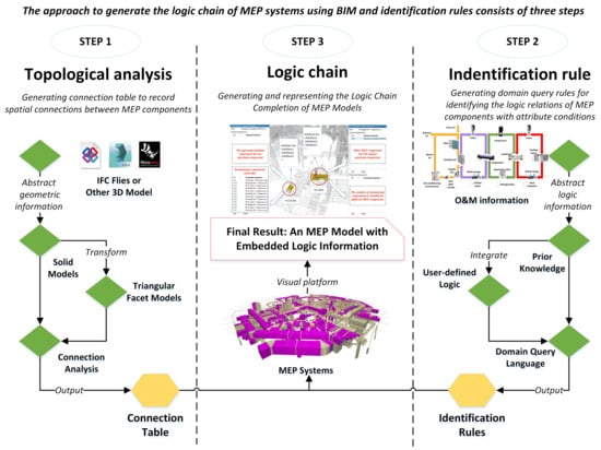
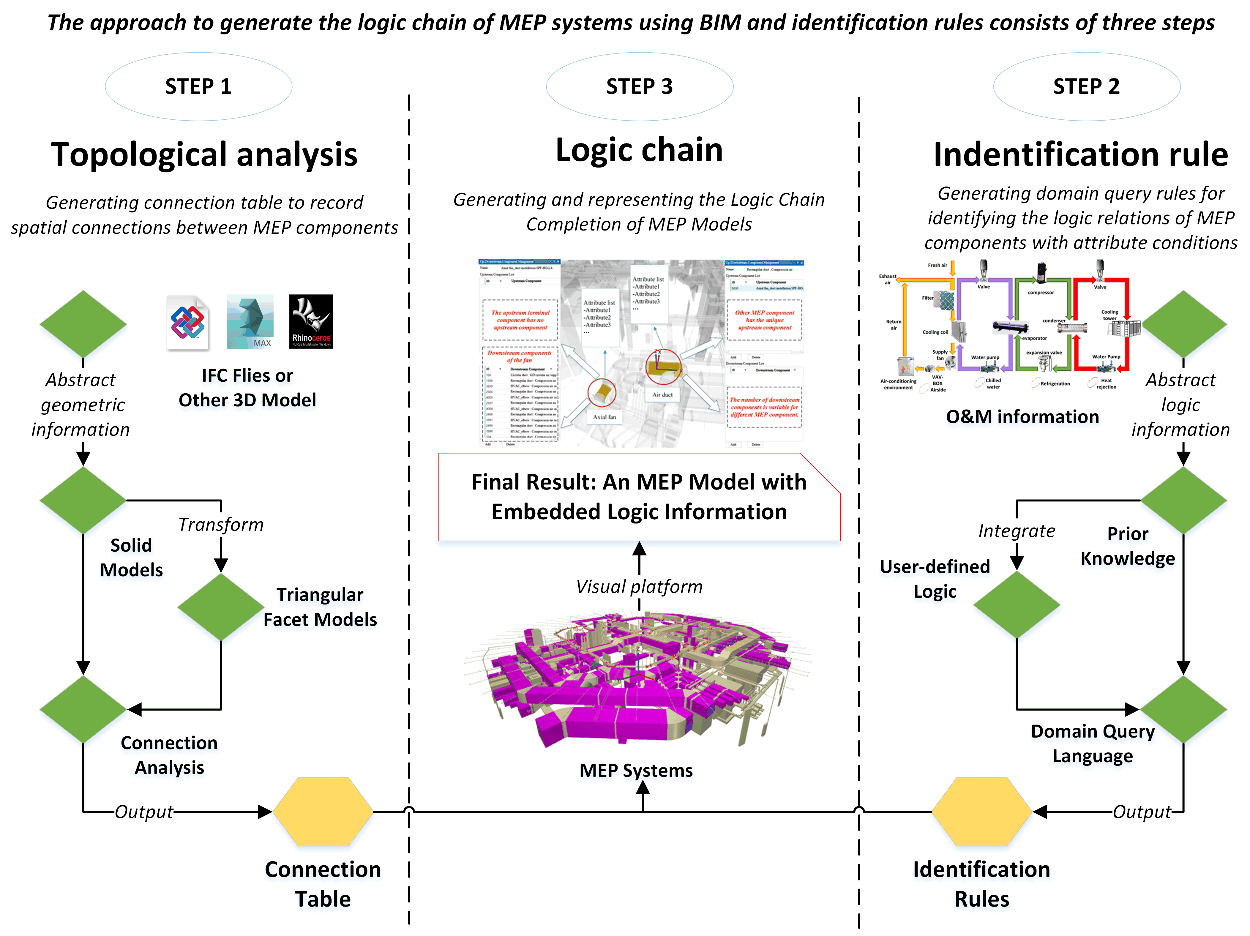
3. An Approach to Generate the MEP Logic Chain from BIMs

This section proposes a three-step approach to generate the MEP logic chain as shown in Figure 3.
The basis of the approach is that the components spatially connected to each other are usually located in the same system. Within this system, it can be further determined that whether they are at the same logic level or closely connected as upstream or downstream components, through prior knowledge or user-defined identification rules. The following three processes utilize the MEP information and some pre-defined knowledge to identify the logic relations among various MEP components.
The first step discussed in Section 3.1 analyses the geometric information of MEP components stored in either IFC or other 3D formats. If the information contained in the existing model is sufficient to assess spatial relations, the relevant parameters in the IFC file are extracted for analysis. If the solid model does not contain the required spatial information, B-rep representations could also be used for topological analysis. B-rep representations will be transformed into triangular facet models for spatial triangle intersection judgments. These two methods will both output a connection table to be used in the following steps. A connection table here refers to a table structure that stores the spatial relation in forms of MEP component pair records indicating the spatial connections in corresponding subsystems.
The second step discussed in Section 3.2 involves the transformation of typical MEP systems and custom information requirements to generate the identification rules. To generate the MEP logic chain, engineers must figure out some logic identification rules to specify which kind of components is upstream or downstream of a specific component. These rules are further divided into two parts. One part is based on the prior experience knowledge, and the other is based on the user-defined logic. The former extracts the upstream and downstream relationships from typical compositions of various MEP systems as a template, while the latter integrates user-defined rules of logic relations according to the characteristics of MEP components as the extended rules for automatic generation. The above two rules utilize a query language to represent their information requirements in formal statements, which are then parsed in the third step.
The third step discussed in Section 3.3 is the retrieval of MEP logics, and completion of the logic chains. The upstream component of a given MEP subsystem will first be determined by identification rules. After creating a graphic structure based on the upstream terminal component and connection table, automatic completion algorithms will perform a traversal searching for a component that meets the requirements of inspections and add upstream or downstream components as extended attributes to represent their logics, an algorithm for selective traversal which uses a tag for each node in the MEP logic tree. [37]

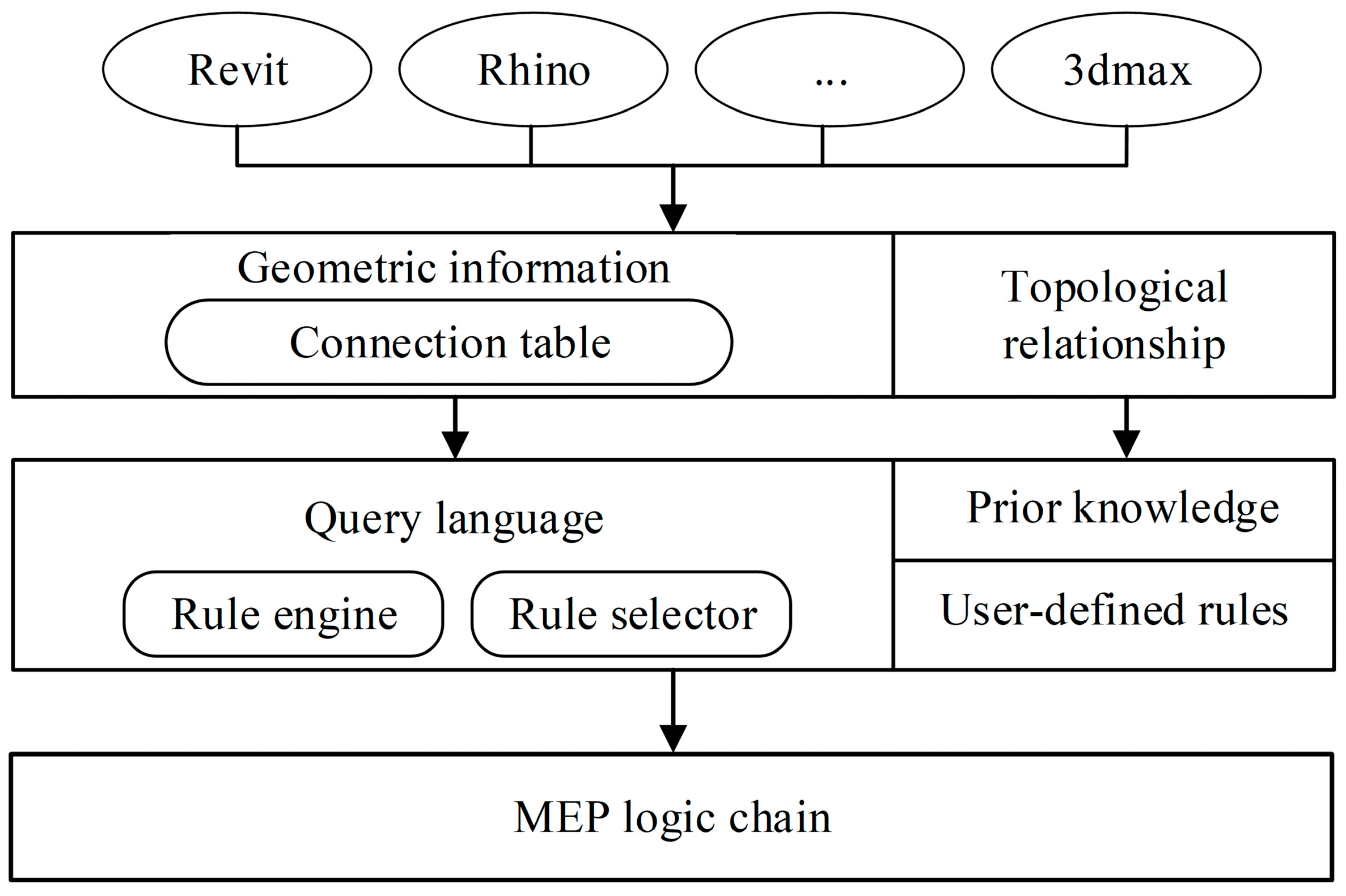
3.1. Spatial Topological Analysis within MEP Models

Different design tasks require different types of topological information. For example, architects pay more attention to the space of the building, whereas MEP engineers focus on the connections between pipelines and air ducts. Due to the lacking logic chain among components in most models delivered by contractors, the upstream or downstream connections of a given component within the MEP system cannot be extracted directly for FM tasks. Therefore, the geometric information of MEP components in BIMs is extracted for analysis to obtain the connectivity between MEP components as the basis for subsequent analyses. There are two kinds of geometric representations, i.e., parametric and nonparametric. Parametric representations describe a shape using a model with pre-defined parameters. For example, a cylinder as a swept solid may be represented by its radius, axis, and the start and end points. In addition, a cylinder can also be represented in nonparametric form, such as in triangles-based B-rep format. Accordingly, spatial topological analysis would be divided into two parts as show in Figure 4, i.e., the IFC-based parametric topological analysis and nonparametric topological analysis.

3.1.1. The IFC-Based Parametric Topological Analysis Algorithm

In the IFC schema, object entities are subtypes of the abstract entity IfcObject. Objects that appear in a spatial or geometric context are described by abstract entities of type IfcProduct. As a subtype of IfcProduct, MEP products are described by the abstract entity IfcElement, which can be connected to other IFC elements. Then the objectified relationship entity IfcRelConnectsElements is used to describe connections between elements. Specific subtypes of IfcElement entities are used to further distinguish the semantic meaning of a MEP product, including specific object entities to describe HVAC elements, plumbing elements, etc. In some well-developed BIMs, the connection information can be extracted directly by IfcDistributionPort, IfcDistributionElement and other tools. As shown in Figure 5, according to IFC schema, MEP components are represented by IfcDistributionElement and its subclasses such as IFCFan and IFCPipeFitting, etc. The connection relationship between these components is represented through IfcDistributionPort. According to the port between the component and connection form, IfcDistributionPort connects to the equipment by IfcRelConnectsPortToElement. The connection relationship between IfcDistributionPort is defined by IfcRelConnectsPorts, and the direction of the upstream and downstream relationship is defined through the two reverse attributes (ConnectedFrom and ConnectedTo) of IfcDistributionPort.
There are two descriptions of connective information in MEP subsystems, implicit connection and explicit connection. For implicit connection, IfcDistributionPort only relies on the MEP equipment or terminal component. If these two equipment or terminals are connected, they are defined in IfcRelConnectsPorts and then the RealizingElement attribute value of the relationship is set to pipe fittings or segments that connect them while, in the explicit connection, the IfcDistributionPort is attached to not only equipment or terminals, but also pipe fittings or segments. The equipment and terminals must be connected via the IfcRelConnectsPorts with pipe fittings or segments that connect them, ignoring the attribute value of the RealizingElement.
Furthermore, geometric information can also be used for topological analysis even if connection information is ignored in BIM model. For example, a pipe is parametrically represented in diverse BIM tools, as a “SweptSolid”, IFC model defines the cross section, the starting position of the extrusion, the direction of the extrusion and its length. The pipe’s Cartesian coordinate value will also be illustrated in the local coordinate system. Using this information, two pipes can be assessed as connected if the cross-section parameters of the starting point of one component is approximately equal to the ones at the end point of another component.

3.1.2. The Nonparametric Topological Analysis Algorithm

There are many other nonparametric data formats available for MEP modeling, such as triangle-based B-rep representations. For example, if these objects are imported through rendering-oriented software such as 3ds Max, or shape-oriented design tools, such as CATIA or Sketch Up. Moreover, some BIM platforms focus on efficient 3D display to help real-time management, and they will transform the parametric models to triangles to enhance the OpenGL or DirectX render efficiencies. Therefore, it is necessary to propose the nonparametric topological analysis algorithm.
Generally, pipe fittings, equipment, and short pipes have different kinds of connections between each other. The connections between segments are usually in one-to-one form, while for fittings and segments are usually in one-to-many form. For example, a reducing tee connects three pipes. Considering the magnitude of errors buried in MEP modeling, a deviation threshold, i.e., 10 mm between outlets of MEP segments, fittings or equipment can be determined as touching. The algorithm to determine the relation between components is depicted as follows.
The test can return the result of spatial analysis of triangles, which distinguish between touching and intersecting triangles. If a pair of triangles from A and B intersect, this also indicates an intersection of the two interiors of the objects under examination. It is possible that A covers B, or vice versa. A and B can, nevertheless, still touch each other. To disprove the inside relationships, the algorithm is realized by means of ray tests. Each vertex of a triangle is used as a starting-point for rays. The rays are emitted from the selected vertex and the number of intersections with the B is counted. An even intersection number indicates that the triangle is located outside, whereas an odd number indicates that the triangle is inside another.
After iterating all components and spaces, the connection tables of the MEP components and the space are ready for the next step. The connection tables can also be used to record the connection components or equipment. Each connection pair indicates that the two components are connected in space, the connection type and the name of components. For example, DS-SS- <E1, E2> indicates that entity E1 is connected to entity E2, both are segments in the duct system. Other typical connection types include FS, ES, which stand for fittings or equipment connected to segment, respectively. Moreover, different types can then be used for analysis of upstream or downstream relations.

3.2. Identification Rules of Logic Chain in MEP Systems

The identification rules refer to domain query rules for identifying the logic relations of MEP components with attribute conditions. As mentioned above, except for the geometric relations among MEP components, specific rules are also needed for identifying which component is the upstream or downstream of the specific component to generate the logic chain. Generally speaking, the methods to establish such rules are extracted from MEP knowledge. This section discusses two kinds of such rules, i.e., the typical prior knowledge rule and the user-defined logic rule. Moreover, a domain-specific query language with pre-defined lexicon and syntax is represented in a formal way to figure out the relationship between upstream and downstream components.

3.2.1. The Typical Prior Knowledge Rule

In each MEP system, countless components formulate a logic web with intertwined relationships. Taking HVAC system as an example, it consists of several circles with different functions. As shown in Figure 6, in most cases, an HVAC system with a chilled water air-handling unit is a common design for general commercial buildings or office buildings. In such a design, the supply air of each floor comes from its engine room, where the air-handling unit consists of cooling coils, filters, and supply fans. The chilled water in the frozen coil is provided by the central chilled water plant in the building and releases heat by cooling tower heat rejection. The cold air produced during refrigeration is circulated to each room by cooling water. The entire system consists of relevant equipment and various types of pipelines and valves. Chillers and air-handling units can be viewed as a whole ignoring their internal logic. Considering the practical requirements of FM and the characteristics of existing HVAC control systems, the upstream and downstream logics between ducts or pipes play important roles in emergency management. For air circulation, the fan can be taken as the ultimate upstream terminal and its downstream components involve the damper, duct and air terminal box. Similarly, an evaporator cooler can be regarded as the upstream terminal component of the water circulation, and its downstream components involve the water pump, valve, and pipe.
Domain schemas of IFC files provide entity classification in different MEP subsystems. This research firstly extracted the logic chain of IfcElement types corresponding to several common MEP subsystems from the knowledge accumulated along with field engineering practices, literatures and manuals of each MEP subsystem. These typical logic chains are summarized in Figure 7.
Take HVAC system as an example, proportional control is one of the control forms in HVAC systems. The valve or damper is positioned in intermediate positions in proportion to the response to slight changes in the controlled condition. A modulating valve controls the amount of chilled water entering a coil so that cool supply air is just sufficient to match the load at a desired setpoint. If the temperature goes beyond the setpoint, the on- and off-times change according to the temperature differences. Thus, according to the control knowledge, if a valve is spatially connected to a cooling coil in HVAC systems, the former one can be determined as the upstream component of latter components. Moreover, a valve entity can be the upstream component of ether pipe fitting or pipe segment which connects them. Particularly, pipe segments connected to each other can be regarded in the same logic level, which means they have the same upstream and downstream components. According to the tabulated rules, the MEP models with correct entity classifications are easy to be placed in the logic chain in most systems.

3.2.2. The User-Defined Logic Rule

According to different MEP design or FM requirements, pre-defined rules stipulated according to prior experience do not always work. Therefore, this approach proposes a user-defined logic rule as a supplementary to pre-defined rules. To define those rules, a domain query language with lexicon and grammar of their statements should be introduced first. The query, for example, may ask for the position of the valve on the supply water pipe connected to the reheat coil in the terminal box [38,39]. The contextual information items used in the query language for HVAC systems can be categorized into three general groups: entities, properties, and relationships. The relationship between entities is simplified as follows: A is the upstream component of B, A is the downstream component of B, or NULL (means without any relationship).
Each entity specifies a type of object that has a set of instances in MEP systems. Hence, in a rule statement, the name of an entity represents all instances with the same name. Each entity contains several property sets, each of which contains a number of properties, such as the component name, ID, or spatial geometry information. This information provides lexicon of upstream and downstream logic rules. Numbers or strings can typically represent the values of these properties. The predicates of these values shown in Table 2 were identified according to SPARQL.
Each property of an entity instance has a set of values that describe the instance. The values can be individual or an array of either a primitive, such as number, character and Boolean, or instances of other entities. Since the values of properties describe the characteristics of the instances, they can be used to specify the target instances. For example, to retrieve the instances of all temperature sensors in the data model, the users can specify the query statements to identify the instances of sensors that have their property “MeasurementType” with value equaling to “Temperature”, such as (Sensor. MeasurementType, =, “Temperature”).
Although the actual relationships between components can be highly complex, the relationship in the user-defined identification rules considered by the algorithm is either “UpstreamOf” or “DownstreamOf”. The upstream and downstream relationships are not interconnected in space, unlike the functional relationships. For example, the valve as a logic upstream component controls its downstream components, such as pipes, and the axial fan as an upstream component will affect the working state of its downstream components, including outlets.
The syntax of a query language specifies the grammar for the logic chain statements. It provides guidelines about how the statements should be parsed and interpreted. After defining the information items in a specific logic chain, the syntax of object-oriented query language rules is extended to express the entity, property and upstream and downstream logic relations. Table 3 provides examples for each definition.

3.3. Logic Chain Completion of MEP Models

Following the steps articulated above, the connection tables and identification rules can be obtained. The connection tables extracted from geometric data provide topological relationships between components. Each component is considered as a node and an edge is then developed between two nodes if their represented components are spatially connected. In addition to the topological relationship, attributes of specific node in different types of systems contribute to generate the logic chain. Identification rules extracted from prior knowledge or user-defined rules are then transformed into computer readable language. The logic query engine retrieves attributes’ information according to the identification rules for establishing the logic chain. An example of an HVAC subsystem is discussed below reveals the mechanism of the MEP logical query engine, as shown in Figure 8.

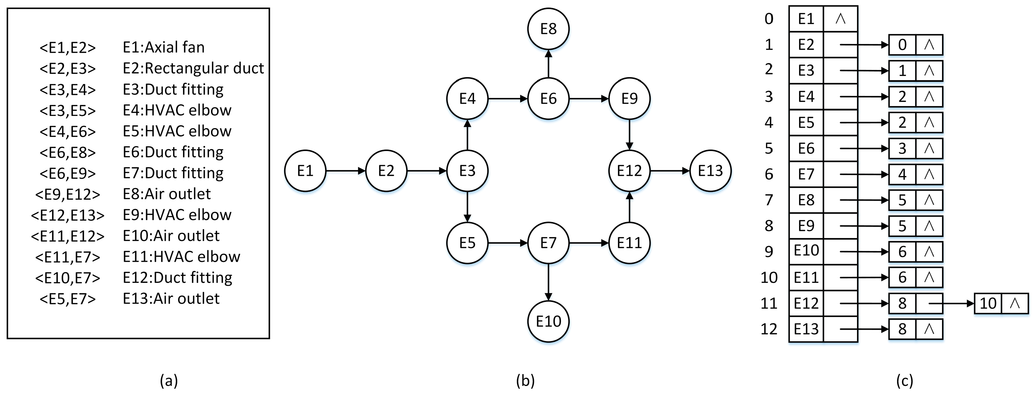
3.3.1. Graph Structure of the MEP Topology

When modeling MEP systems by Revit or other BIM software, the component usually contains extended properties including system type, system classification, and system name. Taking an ordinary duct as an example, these properties can be specified as “air duct system”, “supply air”, and “supply air 8”. Accordingly, this approach firstly parses the model (which can be exported in IFC format) to obtain the hierarchy relationships between MEP systems. The first-level node refers to the system type such as duct or pipe systems pre-defined in Revit. The second-level node refers to the system classification, such as supply air, return air and exhaust air in the duct system. The third-level node refers to the system name that can be defined by users. Some other attributes extracted from MEP model are shown in Table 4.
The list of attributes is assigned to each node. This list acts as the semantic feature of the system topology. It makes the element do have a “meaning” inside the system.
In a subsystem, the proposed approach determines the upstream terminal components by analyzing the identification rules. Considering that there may be some circles within MEP systems, this study selects the graph structure and uses the adjacency list as the data structure. Comparing with the search in the tree structure, graph search has an advantage that whenever the algorithm explores a new node, it marks it as visited. In this study, the node can be marked as an upstream component or downstream component when being visiting.
Taking an HVAC loop subsystem as an example, the graph in Figure 9b shows a simplified supply air system with 13 components, where E1 is the air handing unit, E8, E10, and E13 are VAVs, and the remainders are ducts. After performing the spatial topology analysis discussed in step 1, the connection table is shown in Figure 9a. Each component pair indicates that the two components are spatially connected, where <E1, E2> indicates that air handing units E1 and duct E2 are connected. If entity E1 is selected manually or determined automatically to be the upstream terminal component by identification rules, the algorithm can generate a directed graph as shown in Figure 9b, and E1 will be selected as the start node for the generation of the logical relationships. The completed inverse adjacent list is shown in Figure 9c. Each list describes the set of input nodes of a vertex in the graph.

3.3.2. MEP Logical Query Engine

After generating a directed graph of the MEP subsystem, the breadth search for the directed graph will be performed with each identification rule to append the MEP logic information. The semantic analysis of identification rules will output the requirements of the upstream and downstream components, including the entities, properties, relationships and operations. The search sequence of Figure 9 Note (b) is E1, E2, E3, E4, E5, E6, E7, E8, E9, E10, E11, E12, and E13. For each component meeting the downstream component requirements, the first satisfying upstream component of the same rules searched in the reverse direction of the graph will be defined as the upstream component, and the logic information will be added to the model. An enriched MEP information model with a logic chain can then be generated when the entire subsystem completes the traversal of all identification rules. In this example, the fan is the upstream component of the duct and the duct is the upstream component of the air terminal box. An inspection of the components according to the first rule indicates that E2, E3, E4, E5, E6, E1, E7, E9, E11, and E12 are the downstream components of E1. When considering the second rule, E8, E10, and E13 should be the downstream components of E6, E7, and E12, respectively.

3.3.3. The Enriched MEP Logic Chain Representation

The above-generated MEP logic information will finally be added in the BIM. After generating the attributes list, another issue concerned is how to show the logic information of duct and elements in HVAC systems for checking and tracing purpose. System topology with logic information is a way to present the MEP model in a simple manner such that the system architecture can be easily understood. A typical MEP services layout consists of air ducts, water pipes, equipment, cable containment, etc. Taking a typical layout plan for HVAC air-side services (see above half of Figure 10) as an example, it is too complicated for engineers to know how the system is designed and how it works.
Obtaining the upstream and downstream elements is inconvenient with complex HVAC lines in 2D drawings and requires professional skills. The large size and dual-line representation of the air duct and equipment result in such congested drawings. The bottom half of Figure 11 shows a system logic representation of an HVAC subsystem. The duct fittings and equipment are denoted by 3D models to identify their location and connectivity. When considering BIM integrated with logic information, the MEP models provide the upstream and downstream component list of selected nodes. In user interface, the logic management panel provides the upstream and downstream component list of selected nodes. The downstream list of axial fans includes several ducts, elbows, fire dampers and transitions; meanwhile the upstream component of the duct is the axial fan. There is only one upstream component for each MEP component except for the upstream terminal one. Thus, the axial fan has many downstream components but no upstream components, and the duct has an upstream component but no downstream component.
The connection relationship and MEP logic information will finally be added in the FM model which can be described by IFC. The IfcRelConnectsElements as an objectified one-to-one relationship provides the generalization of the connectivity between elements. The concept of two elements being spatially or logically connected could be described independently from the connecting elements. The spatial connectivity may contain related geometric representation of the connected entities. As shown in Figure 11, In this case the geometrical constraints of the connection are provided by the optional relationship to the IfcConnectionGeometry. The connection geometry is provided as a point, curve, or surface within the local placement coordinate systems of the connecting elements. If the logic connection is developed by the above algorithm based on connection relationship, the connection geometry can be replaced by logic information within the extended property set which conclude the extended properties of RelUpstreamElement and RelDownstreamElement.

4. A Case Study

4.1. Introduction to the Project

The China Resources headquarters building is around 400 m high with a construction area of 267,137 m2. It has four floors below and 66 floors above ground. The MEP systems contain HVAC, electric, plumbing, anti-power, and anti-water. The structural and MEP models were created in Revit, and the MEP model was used as a case study (Figure 12). Related information of MEP components (e.g., suppliers, manufacturing date, code) were continuously input during the modeling and construction stage for O and M staff to complete the MEP logic chain among components based on the automatic completion approach proposed in this study. The principles of the upstream and downstream relations were as follows. In the following part, the duct system was illustrated in detail.

4.2. Application Details of the Approach

Modeling of the MEP systems was performed mainly on Revit. In addition, other software such as 3dx Max was used for design and evaluation of the accuracy of the MEP model. One of the differences between them was that the geometric data of IFC files exported by Revit included axes information for spatial relationship analysis. After extracting the system type and system classification of MEP systems from IFC files, the supply air subsystem was selected to complete its logic chain. First, the approach determined the upstream terminal component in the subsystem by identification rules and users, as shown in Figure 13. The connection table was then automatically generated, and a set of components represented a spatially connected path by the same color. As shown in Figure 13, the fan is the upstream component of fire dampers, ducts, elbows, and transitions. Outlets are the downstream components of transitions. The axial fan is the upstream terminal component, as well as the start node of the directed graph traversal.
The method was also verified in the fire sprinkler system, where the riser is the upstream component of valves, pipes, transitions, and elbows, while sprinklers are the downstream components of transitions. The pipes include feed mains, cross mains, and branch lines. Most of the logic chain were generated based on prior knowledge while several user-defined rules, as shown in Table 5, were added as a supplement before retrieving the fire sprinkler system.

4.3. Evaluation and Discussion

A total of 15 subsystems in HVAC, including fresh air, air supply and exhaust air systems, and 10 subsystems in fire sprinkler systems, including wet pipe sprinkler systems and dry pipe sprinkler systems were described and discussed. Each subsystem contains 20–40 components, with a total number of 763 components in the HVAC and fire sprinkler system. Table 6 summarizes the number of omissions and errors that occurred. The statistical results demonstrate that there are one or more omissions in the process for generating the connection table in six subsystems and one error in the process for generating the logic model in four subsystems.
From this case study, the following conclusions can be drawn.
  • In 15 subsystems, both the connection table and logic model were generated with 100% accuracy, demonstrating that the approach could generate the right logic chain.
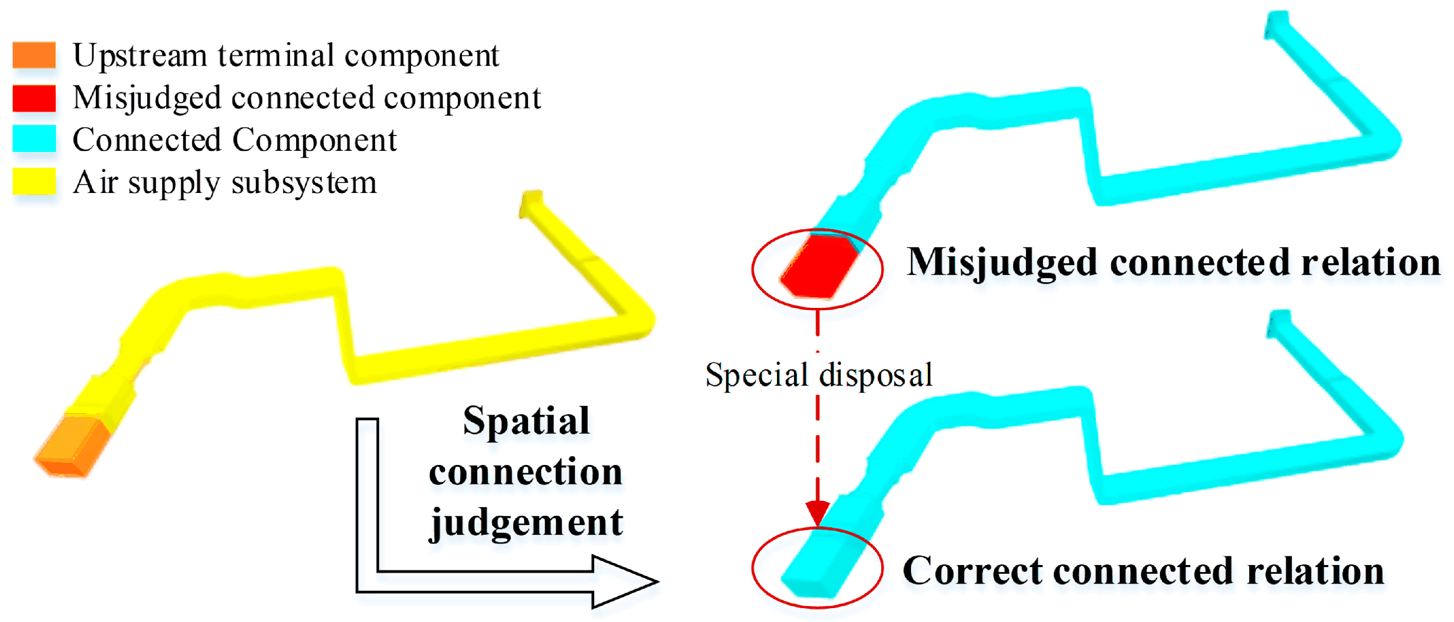
  • There were ten subsystems with 1–5 omissions when generating the connection tables, and the accuracy rates remained higher than 80%. The spatial connection was misjudged for the following reasons in these cases:
    • There were deviations in the position of the component during modeling. When the model was observed under magnification, there was no connection between components that were, in fact, connected to each other in practical engineering.
    • A portion of the information was missing or incorrect in the modeling process. System classification and system name attributes were missing or missing in certain subsystem components’ properties, which influenced the inspection of components.
    • The intersection judgment of space triangles was not sufficiently accurate. Because the triangular size was small, improper handling of truncation errors for intermediate calculations considerably affected on the results. Therefore, the algorithm should be improved.
    Among the three types of problems, missing or incorrect information during modeling occurred most frequently, followed by misjudgments of triangle intersections and then deviations in the component positions during modeling. During the modeling process, information about the system classification and system name were generally inputted in commercial software. Designers or modelers were likely to ignore the accuracy of relevant property information, which, when combined with the lack of relevant modeling standards, led to the problem of missing or incorrect information.
    If two components of a subsystem were spatially connected to each other but the model assessed the connection incorrectly, the two components were distinguished as shown as Figure 14. In addition, the connection table could be manually added with two adjacent components to correct such omissions so that a complete connected path could be obtained.
  • There were four subsystems with less than two errors when generating logic models and the accuracy rates remained higher than 90%. An analysis of the results demonstrated that the values of properties were ambiguous in terms of their semantic meanings. For example, the fire damper was one of the valves in the HVAC system. However, if users used “valve” to represent the damper instead of using “damper”, the algorithm was unable to match the valve description with the fire damper component. Such problems were corrected by adding and deleting upstream and downstream components manually.
The results also indicated that this approach could achieve the automatic completion of logic chain. As discussed above, one limitation of this approach is because there was no unified modeling standard for MEP systems, the omission of certain necessary data in the model would deduce the accuracy.

5. Conclusions and Future Work

Implementations of BIM technology can provide visualization and integrated information models for FM. However, the logic relationships between MEP components are often ignored not only during the modeling process but also in the widely adopted IFC standard. Considering that manual generation of the logic chain is time and labor consuming, this study proposes an approach to generate the logic chain for MEP systems from BIM with identification rules.
The approach consists of three steps which focus on the geometric information of MEP models, identification rules for logic inferences and the data structure of MEP components, respectively. The assessment of IFC-based spatial relationships is mainly based on 3D solid models or triangular facet models. The identification rules of MEP systems contain typical prior knowledge and user-defined logic rules. After determining the connection table, classification rules, and the terminal component, the graph data structure can be generated to represent the relationships between MEP components. Finally, the logic is generated by performing traversal searching for each connected pair of components with an appropriate identification rule.
The feasibility and accuracy of the approach were tested in an MEP model of an actual project. The results indicated that the approach was capable of generating logic chains for different subsystems and the accuracy of generating both connection tables and logic model exceeded 80% in 15 subsystems. Some problems, such as mismatching, occurred during the tests while they were discussed to be solved by adding connections or logic information manually.
Future works will focus on improving the accuracy of the approach and exploring efficient control methods of energy conservation based on the MEP logic chain and related control theories of MEP systems. Based on the experiences gained from this application, more service-oriented functions can be developed for FM depending on a thorough exploration and a comprehensive application of BIM and related information technologies.

Author Contributions

Conceptualization: S.-W.L. and Z.-Z.H.; data processing: Y.-Q.X.; funding acquisition: Z.-Z.H.; methodology: Y.-Q.X.; software: Y.-Q.X.; supervision: S.-W.L. and Z.-Z.H.; validation: Y.-Q.X. and Z.-Z.H.; visualization: Y.-Q.X.; writing—original draft: Y.-Q.X.; writing—review and editing: Z.-Z.H. and S.-W.L.

Funding

This research is supported by the National Key R&D Program of China (no. 2017YFC0704200), the National Natural Science Foundation of China (no. 51778336 and no. 51478249), and the Tsinghua University-Glodon Joint Research Centre for Building Information Model (RCBIM).

Acknowledgments

The authors also thank Pine Liu (Carnegie Mellon University) and Kincho H. Law (Stanford University) for their valuable comments and contributions.

Conflicts of Interest

The authors declare no conflict of interest.

References

  1. Akbarnezhad, A.; Ong, K.C.G.; Chandra, L.R. Economic and environmental assessment of deconstruction strategies using building information modeling. Autom. Constr. 2014, 37, 131–144. [Google Scholar] [CrossRef]
  2. Akcamete, A.; Akinci, B.; Garrett, J.H. Potential utilization of building information models for planning maintenance activities. In Proceedings of the 13th International Conference on Computing in Civil and Building Engineering, Nottinham, UK, 30 June–2 July 2010; pp. 151–158. [Google Scholar]
  3. Chotipanich, S. Positioning facility management. Facilities 2004, 22, 364–372. [Google Scholar] [CrossRef]
  4. Shen, W.; Hao, Q.; Mak, H.; Neelamkavil, J.; Xie, H.; Dickinson, J.; Thomas, R.; Pardasani, A.; Xue, H. Systems integration and collaboration in architecture, engineering, construction, and facilities management: A review. Adv. Eng. Inform. 2010, 24, 196–207. [Google Scholar] [CrossRef] [Green Version]
  5. Parn, E.A.; Edwards, D.J.; Sing, M.C.P. The building information modelling trajectory in facilities management: A review. Autom. Constr. 2017, 75, 45–55. [Google Scholar] [CrossRef] [Green Version]
  6. Becerik-Gerber, B.; Jazizadeh, F.; Li, N.; Calis, G. Application Areas and Data Requirements for BIM-Enabled Facilities Management. J. Constr. Eng. Manag. 2012, 138, 431–442. [Google Scholar] [CrossRef]
  7. Hu, Z.-Z.; Tian, P.-L.; Li, S.-W.; Zhang, J.-P. Bim-Based Integrated Delivery Technologies for Intelligent Mep Management in the Operation and Maintenance Phase. Adv. Eng. Softw. 2018, 115, 1–16. [Google Scholar] [CrossRef]
  8. Chen, S.; Zheng, J.; Bi, K.; Zhang, P. BIM-Based Logic Retrieval of MEP Systems. J. Eng. Manag. 2016, 30, 132–137. [Google Scholar]
  9. BuildingSMART. IFC4 Release Candidate 4. Retrieved from BuildingSMART. 2013. Available online: http://www.buildingsmart-tech.org/ifc/IFC2x4/rc4/html/index.html (accessed on 24 September 2015).
  10. Kassem, M.; Kelly, G.; Dawood, N.; Serginson, M.; Lockley, S. BIM in facilities management applications: A case study of a large university complex. Built Environ. Proj. Asset Manag. 2015, 5, 261–277. [Google Scholar] [CrossRef]
  11. Lee, Y.C.; Eastman, C.M. Logic for ensuring the data exchange integrity of building information models. Autom. Constr. 2018, 93, 388–401. [Google Scholar] [CrossRef]
  12. Hassanain, M.A.; Froese, T.M.; Vanier, D.J. Development of a maintenance management model based on IAI standards. Artif. Intell. Eng. 2001, 15, 177–193. [Google Scholar] [CrossRef] [Green Version]
  13. Krijnen, T.; Beetz, J. An IFC schema extension and binary serialization format to efficiently integrate point cloud data into building models. Adv. Eng. Inform. 2017, 33, 473–490. [Google Scholar] [CrossRef] [Green Version]
  14. Cho, G.H.; Won, J.S.; Kim, J.-U. The Extension of IFC Model Schema for Geometry Part of Road Drainage Facility. J. Korea Acad. Ind. Cooper. Soc. 2013, 14, 5987–5992. (In Korea) [Google Scholar] [CrossRef] [Green Version]
  15. Brilakis, I.; Lourakis, M. Toward automated generation of parametric BIMs based on hybrid video and laser scanning data. Adv. Eng. Inform. 2010, 24, 456–465. [Google Scholar] [CrossRef]
  16. Nguyena, T.H.; Oloufa, A.A.; Nassar, K. Algorithms for automated deduction of topological information. Autom. Constr. 2005, 14, 59–70. [Google Scholar] [CrossRef]
  17. Bruno, S.; De Fino, M.; Fatiguso, F. Historic building information modeling: Performance assessment for diagnosis-aided information modeling and management. Autom. Constr. 2018, 86, 256–276. [Google Scholar] [CrossRef]
  18. Nepal, M.P.; Staub-French, S.; Zhang, J. Deriving construction features from an IFC model. In Proceedings of the Annual Conference–Canadian Society for Civil Engineering, Québec, QC, USA, 10–13 June 2008. [Google Scholar]
  19. Borrmann, A.; Rank, E. Specification and implementation of directional operators in a 3D spatial query language for building information models. Adv. Eng. Inform. 2009, 23, 32–44. [Google Scholar] [CrossRef]
  20. Daum, S.; Borrmann, A. Processing of Topological BIM Queries using Boundary Representation Based Methods. Adv. Eng. Inform. 2014, 28, 272–286. [Google Scholar] [CrossRef] [Green Version]
  21. Bertino, E.; Negri, M.; Pelagatti, G.; Sbattella, L. Objectoriented query languages: The notion and the issues. IEEE Trans. Knowl. Data Eng. 1992, 4, 223–237. [Google Scholar] [CrossRef]
  22. Kang, T.W. Object composite query method using IFC and LandXet ML based on BIM linkage model. Autom. Constr. 2017, 76, 14–23. [Google Scholar] [CrossRef]
  23. Mazairac, W.; Beetz, J. BIMQL—An open query language for building information models. Adv. Eng. Inform. 2013, 27, 444–456. [Google Scholar] [CrossRef]
  24. Dong, J.S.; Feng, Y.; Sun, J. Sensor Based Designs for Smart Space; Technical Report; Computer Science Department, National University of Singapore: Singapore, 2004. [Google Scholar]
  25. Solihin, W.; Eastman, C.; Lee, Y.C. A simplified relational database schema for transformation of BIM data into a query-efficient and spatially enabled database. Autom. Constr. 2017, 82, 367–383. [Google Scholar] [CrossRef]
  26. Preidel, C.; Daum, S.; Borrmann, A. Data retrieval from building information models based on visual programming. Vis. Eng. 2017, 5, 18–32. [Google Scholar] [CrossRef]
  27. Thambirajah, J.; Benabbas, L.; Bauer, M.; Thornhill, N.F. Cause-and-effect analysis in chemical processes utilizing XML, plant connectivity and quantitative process history. Comput. Chem. Eng. 2009, 33, 503–512. [Google Scholar] [CrossRef] [Green Version]
  28. Son, H.; Kim, C.; Kim, C. 3D reconstruction of as-built industrial instrumentation models from laser-scan data and a 3D CAD database based on prior knowledge. Autom. Constr. 2015, 49, 193–200. [Google Scholar] [CrossRef]
  29. Tang, P.B.; Huber, D.; Akinci, B.; Lipman, R.; Lytle, A. Automatic reconstruction of as-built building information models from laser-scanned point clouds: A review of related techniques. Autom. Constr. 2010, 19, 829–843. [Google Scholar] [CrossRef]
  30. Liu, H.; Singh, G.; Lu, M.; Bouferguene, A.; Alhussein, M. BIM-based automated design and planning for boarding of light-frame residential buildings. Autom. Constr. 2018, 88, 235–249. [Google Scholar] [CrossRef]
  31. Yarmohammadi, S.; Castro-Lacouture, D. Automated performance measurement for 3D building modeling decisions. Autom. Constr. 2018, 93, 91–111. [Google Scholar] [CrossRef]
  32. Leite, F.; Akcamete, A.; Akinci, B. Analysis of modeling effort and impact of different levels of detail in building information models. Autom. Constr. 2011, 20, 601–609. [Google Scholar] [CrossRef]
  33. Ciribini, A.L.C.; Mastrolembo Ventura, S.; Paneroni, M. Implementation of an interoperable process to optimise design and construction phases of a residential building: A BIM Pilot Project. Autom. Constr. 2016, 271, 62–73. [Google Scholar] [CrossRef]
  34. Wang, L.; Leite, F. Process Knowledge Capture in BIM-Based Mechanical, Electrical, and Plumbing Design Coordination Meetings. J. Comput. Civ. Eng. 2016, 30, 04015017. [Google Scholar] [CrossRef]
  35. Hu, Z.Z.; Zhang, J.P.; Yu, F.Q. Construction and facility management of large MEP projects using a multi-Scale building information model. Adv. Eng. Softw. 2016, 100, 215–230. [Google Scholar] [CrossRef]
  36. Li, W.; Fernanda, L. Knowledge Discovery of Spatial Conflict Resolution Philosophies in BIM-Enabled MEP Design Coordination Using Data Mining Techniques: A Proof-of-Concept. In Proceedings of the ASCE International Workshop on Computing in Civil Engineering, Los Angeles, CA, USA, 23–25 June 2013; pp. 419–426. [Google Scholar] [CrossRef]
  37. Driscoll, J.R.; Lien, Y.E. A selective traversal algorithm for binary search trees. Commun. ACM 1978, 21, 445–447. [Google Scholar] [CrossRef]
  38. Djuric, N.; Novakovic, V.; Frydenlund, F. Heating system performance estimation using optimization tool and BEMS data. Energy Build. 2008, 40, 1367–1376. [Google Scholar] [CrossRef] [Green Version]
  39. Liu, X.S.; Akinci, B.; Bergés, M.; Garrett, J.H., Jr. Domain-Specific Querying Formalisms for Re-trieving Information about HVAC Systems. J. Comput. Civ. Eng. 2014, 28, 40–49. [Google Scholar] [CrossRef]
Figure 1. Typical logic chain in the subsystem of HVAC.
Applsci 09 02204 g001
Figure 2. The foundations of automatically generating MEP logical relationships. MEP: Mechanical, Electrical, and Plumbing.
Applsci 09 02204 g002
Figure 3. Flow diagram of the automatic completion mechanism.
Applsci 09 02204 g003
Figure 4. BIM-based topological analysis within MEP systems.
Applsci 09 02204 g004
Figure 5. Expression of MEP connection information in IFC.
Applsci 09 02204 g005
Figure 6. Four circles of HVAC systems.
Applsci 09 02204 g006
Figure 7. Typical logic relationships of Element types within several MEP subsystems.
Applsci 09 02204 g007
Figure 8. The workflow of logical relationships completion of MEP model.
Applsci 09 02204 g008
Figure 9. Data structure of MEP subsystem’s components. (a) Connection table for illustrating topological relationships. (b) Graph structure of the MEP subsystem. (c) Inverse adjacent list of MEP components.
Applsci 09 02204 g009
Figure 10. The HVAC system layouts.
Applsci 09 02204 g010
Figure 11. The EXPRESS-G representation of element connection in BIM.
Applsci 09 02204 g011
Figure 12. The MEP model for the 5th floor of the Chinese resource headquarters building.
Applsci 09 02204 g012
Figure 13. Data structure of a supply air system.
Applsci 09 02204 g013
Figure 14. Results of spatial connection judgement within an MEP subsystem.
Applsci 09 02204 g014
Table 1. Comparison of methods for generating MEP relationships.
ClassRelationship ModelingRelationship Completion ModePlatformGeometric Data Source
Sub-ClassSpatialLogicManualAutomaticBusiness SoftwareSelf-Developed EngineIFC Files3D CAD Model3D Point Clouds from Laser-Scan Data
Son et al. [28]
Hu et al. [7,35]
Nguyena et al. [16]
Borrmann et al. [19]
Chen et al. [8]
Proposed approach
Table 2. Predicates reused from SPARQL for the inspection rules.
PredicateSyntaxDescription
=v1 = v2True if value v1 equals to v2
Containsv1 contains v2true if value v2 is a substring of value v1
Connectsv1 connects v2true if value v2 is topologically connected to value v1
Table 3. Description and examples of the syntax.
DefinitionSyntaxExampleExplanations
1EValveE represents an entity type that defines the scope of an entity to which an inspection rule is applied.
2 E U . P Valve.Name E U represents an inspection rule, and P is an attribute of the relevant component; then, R U E . P is the specified attribute value of the upstream component examined by the inspection rule.
3 R U E = ( E U . P , θ , v ) (Valve.Name, contains, “XX”) E U represents an inspection rule, P is an attribute of the relevant component, θ is a predicate, and v is the value; then, R U E = ( R U E . P , θ , v ) is an inspection rule for all instances in UE that have values for property P that satisfy the predication.
4 ( R U E , R , R D E ) ((Valve.Name, contains, “XX”), UpstreamOf, (Pipe.Name, contains, “XX”))If R U E and R D E are two queries for instances and R provides a relationship (UpstreamOf or DownstreamOf) of these two groups of instances, then ( R U E , R , R D E ) is a complete inspection rule for the generated part of the MEP logic chain.
Table 4. Example of the attributes list.
AttributesTypesBrief Description
Element IdNumberUnique Id in BIM model for every element.
Element LocationCoordinate PointThe element location point.
Space LocatedStringThe spaces of this element located.
System classificationStringThe system classification includes supply air, return air, etc.
System nameStringThe name of system which elements belong to, such as supply air, return air, etc.
FlowNumberFlow in and out of a diffuser or duct.
Start PointCoordinate PointStart point of a duct. For duct only.
End PointCoordinate PointEnd point of a duct. For duct only.
Table 5. Part of inspection rules of MEP subsystem.
No.Inspection Rules of A Supply Air Subsystems
1(Component.Name, contains, “Fan”), UpstreamOf, (Valve.Name, contains, “FAD”)
2(Component.Name, contains, “Fan”), UpstreamOf, (Duct.Name, contains, “duct”)
3(Component.Name, contains, “Fan”), UpstreamOf, (Duct.Name, contains, “elbow”)
4(Component.Name, contains, “Fan”), UpstreamOf, (Duct.Name, contains, “Transition”)
5(Duct.Name, contains, “Transition”), UpstreamOf, (Duct.Name, contains, “outlet”)
No.Inspection Rules of A Fire Sprinkler Subsystems
1(Component.Name, contains, “Riser”), UpstreamOf, (Pipe.Name, contains, “Valve”)
2(Component.Name, contains, “Riser”), UpstreamOf, (Pipe.Name, contains, “pipe”)
3(Component.Name, contains, “Riser”), UpstreamOf, (Pipe.Name, contains, “elbow”)
4(Component.Name, contains, “Riser”), UpstreamOf, (Pipe.Name, contains, “Transition”)
5(Duct.Name, contains, “Transition”), UpstreamOf, (Pipe.Name, contains, “sprinkler”)
Table 6. Performance of the algorithms developed for generating MEP logic models.
Subsystem NameNumber of ComponentsGenerate Connection Table ProcessGenerate Logic Model Process
Omissions (Pairs)Accuracy (%)Errors (Pairs)Accuracy (%)
Return air 12301000100
Return air 2190100196.8
Return air 328388.9292.6
Return air70395.7395.7
Supply air 132196.80100
Supply air 23401000100
Supply air 34101000100
Supply air 432296.70100
Supply air 52301000100
Supply air 62601000100
Supply air188398.40100
Intake air 1211950100
Intake air 21901000100
Intake air 329582.1292.9
Intake air 424291.3195.7
Intake air 53201000100
Intake air 63501000100
Intake air160895398.1
Wet pipe 12301000100
Wet pipe 22801000100
Wet pipe 340197.52100
Wet pipe 434197.11100
Wet pipe 52301000100
Wet pipe 63001000100
Wet pipe178298.9398.3
Dry pipe 12001000100
Dry pipe 22801000100
Dry pipe 3140100285.7
Dry pipe 433197.00100
Dry pipe 52801000100
Dry pipe 644295.5295.5
Dry pipe167398.20100

