Article

Dynamic Response Analysis of a Simply Supported Double-Beam System under Successive Moving Loads

1
School of Civil Engineering, Central South University, Changsha 410075, China
2
National Engineering Laboratory for High Speed Railway Construction, Changsha 410075, China
*
Author to whom correspondence should be addressed.
Appl. Sci. 2019, 9(10), 2162; https://doi.org/10.3390/app9102162
Submission received: 16 April 2019 / Revised: 19 May 2019 / Accepted: 21 May 2019 / Published: 27 May 2019
(This article belongs to the Special Issue Bridge Dynamics)

Abstract

:
The dynamic response of a simply supported double-beam system under moving loads was studied. First, in order to reduce the difficulty of solving the equation, a finite sin-Fourier transform was used to transform the infinite-degree-of-freedom double-beam system into a superimposed two-degrees-of-freedom system. Second, Duhamel’s integral was used to obtain the analytical expression of Fourier amplitude spectrum function considering the initial conditions. Finally, based on finite sin-Fourier inverse transform, the analytical expression of dynamic response of a simply supported double-beam system under moving loads was deduced. The dynamic response under successive moving loads was calculated by the analytical method and the general FEM software ANSYS. The analysis results show that the analytical method calculation results are consistent with ANSYS’ calculation, thus validating the analytical calculation method. The simply supported double-beam system had multiple critical speeds, and the flexural rigidity significantly affected both peak vertical displacement and critical speed.

1. Introduction

Single-beam structures, one-dimensional continuous systems with different excitations and various boundary conditions, have been investigated extensively for many decades. The solutions and theories of dynamic problems of a single-beam structure are perfect [1,2,3,4,5,6,7]. Based on previous studies on single beams, a double-beam system, consisting of two one-dimensional continuous beams connected by a layer, is suggested. In fact, double-beam systems have attracted much attention from researchers and engineers in the past decade.
Based on the assumption that both beams of system are identical, Chen and Sheu [8] studied the dynamic response, free vibration, and static buckling of two parallel beams with different boundary conditions and a viscoelastic material layer in between. Similarly, Vu and Ordonez et al. [9] introduced a method to analyze a double-beam system subject to harmonic excitation with boundary conditions that must be the same on the same side. Rusin and Śniady et al. [10] considered the dynamic response of a double-identical-string system traversed by a constant or harmonically oscillating moving load. Using a simple change of variables to decouple two governing equations describing the vibration of two beams, Wu and Gao [11] developed analytical solutions for the dynamic deflections of both beams under moving harmonic loads. However, many researchers reject this assumption due to the limitations of identical beam systems. Based on previous studies for double-string systems [12], Oniszczuk [13] provided analytical solutions for the free and forced vibrations of an elastically connected complex double-beam system with a simply supported boundary condition. Li and Hua [14] reported a spectral finite-element method for a general double-beam system with unequal flexural rigidities, unequal masses, and arbitrary boundary conditions to investigate the free vibration characteristics. Zhang and Lu et al. [15] investigated the free and forced transverse vibrations of an elastically connected simply supported double-beam system under a compressive axial load. Furthermore, new advances have been made in the research of double-beam systems in recent years. Palmeri and Adhikari [16] proposed a novel state-space form to study the transverse vibrations of a double-beam system with inhomogeneous beams, arbitrary boundary, and rate-dependent constitutive law for the inner layer. Stojanović and Kozić [17] developed the general analytical solutions of forced vibrations of beams subjected to compressive axial loading and arbitrarily distributed continuous loads. Using the direct Lyapunov method and simplifying the system, Pavlović and Kozić et al. [18] investigated the stability and instability of a double-beam system under compressive axial loading. Li and Hu et al. [19,20] applied a modal-expansion method to determine the forced vibration responses of a double-beam system when interconnected by a viscoelastic layer and joined by a uniformly distributed connecting elastic layer. Wu and Gao [21] studied the dynamic response of a double-beam system under a moving oscillator and solved the problem using a single-step scheme.
Double-beam systems play an important role in many fields of structural engineering, such as sandwich or composite beams, and nanostructures. Nanobeams as an important element in highly accurate small-scale devices, and are used as nanosensors, nanoresonators, nanoactuators, nanoswitches, etc. These structures have the advantage of size, scale, and significant mechanical behavior, which makes them applicable in different systems. Murmu [22] mentioned that the nanobeam is an important element and is being extensively used for reliable and computationally efficient analysis of nanostructures, namely nanosensors, nanoresonators, and nanoswitches. Double nanobeam systems with great application in nano-optomechanical systems and sensors are one of the main nanostructures being investigated [23]. It was suggested that the applications of double-nanobeam systems are important in nano-optomechanical systems [24]. Murmu and Adhikari [22,25] analyzed the free bending and longitudinal vibrations of a double-nanobeam system (DCNTS) within the framework of nonlocal elasticity theory. Assuming that two nanotubes are identical, an analytical method for the forced vibration of an elastically connected DCNTS with a moving nanoparticle was developed by Şimşek [26]. Moreover, The double-beam model has also been widely used in studying the dynamic response of bridge-rail systems under moving loads [27,28,29,30,31,32]. Hussein and Hunt [33] used an infinite double-beam system under moving loads to simulate floating-slab tracks and investigated the vibration of the system, in which the characteristics of two beams were different. Xin and Gao [34] studied the vibration transmission from slab track structures into a bridge and used the finite-element method and multibody dynamics theory to solve the problem.
The literature review indicates that the existing studies on the dynamics of double-beam systems have mainly focused on the dynamic response under free vibration and individual moving loads according to relatively complex calculation methods, but they have rarely evaluated the dynamic response of simply supported double-beam systems under successive moving loads in arbitrary spaces and sizes. A model was developed in this study for analyzing the dynamic response of a simply supported double-beam system under successive moving loads in arbitrary spaces and sizes; in order to reduce the difficulty of solving the equation, finite sin-Fourier transform was used to transform the infinite-degree-of-freedom double-beam system into a superimposed infinite number of a two-degrees-of-freedom system and obtain the analytical expression of its dynamic response. Based on a double-beam system under load-groups containing several moving loads, the analytical method proposed in this paper was used to calculate its dynamic response, and the calculation results were consistent with those obtained from the ANSYS finite-element numerical method, thus demonstrating the effectiveness of the analytical method proposed in this paper; some meaningful conclusions for engineering design were drawn as well. The analytical calculation method proposed in this paper for studying the dynamic response of a double-beam system under successive moving loads is briefer than previous methods and provides a theoretical foundation for further engineering applications of double-beam systems.

2. Vertical Dynamic Response of a Simply Supported Double-Beam System

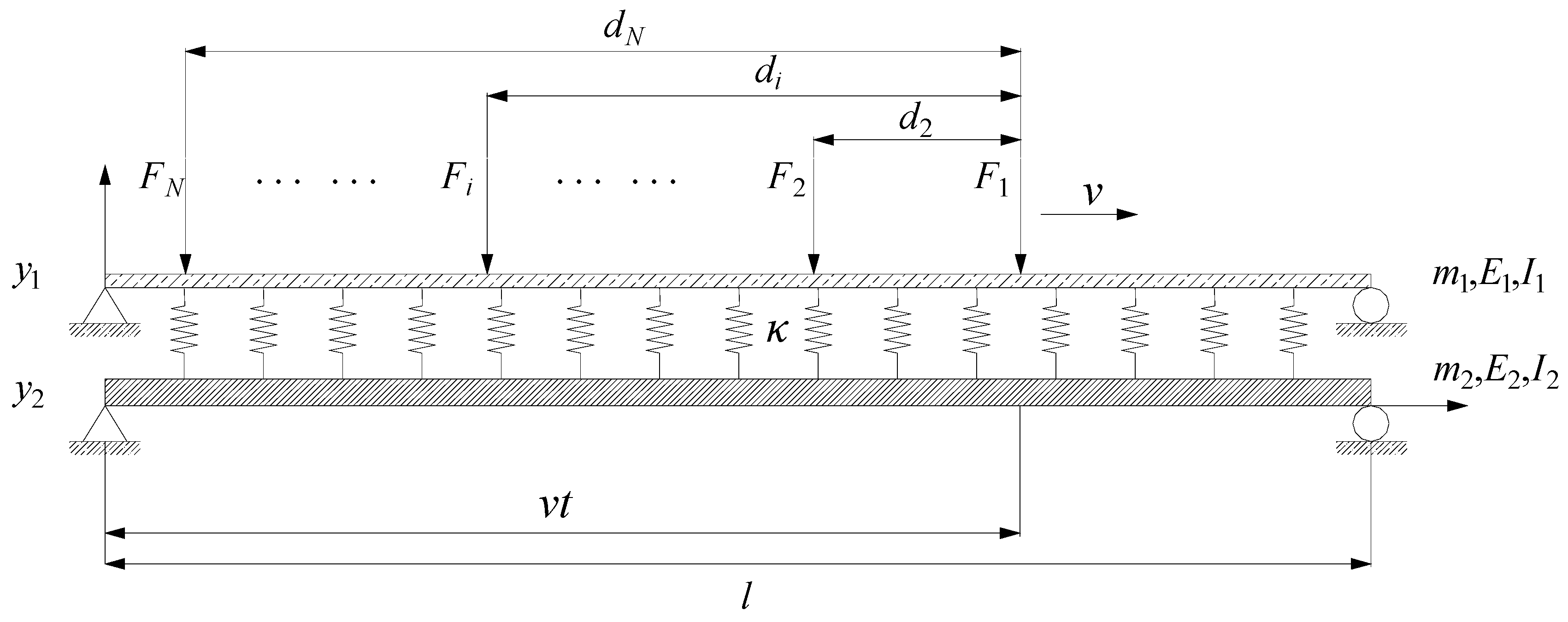
2.1. Mathematical Model Building and Parameter Solving

Figure 1 shows a simply supported double-beam system under successive moving loads in arbitrary spaces and sizes; after introducing a constructor S ( ζ ) , the successive moving loads P ( t ) can be expressed as follows:
P ( x , t ) = i = 1 N F i δ [ x v ( t t i ) ] S [ v ( t t i ) l ]
S ( ζ ) = { 1 0 ζ 1 0 else
where δ is Dirac function; l is the length of a simply supported double-beam system; F i is the ith moving load. It is assumed that F 1 acts on x = 0 at the initial moment ( t = 0 ); t i = d i / v , d i represents the distance from F i to F 1 .
The vertical vibration of the double-beam system shown in Figure 1 is governed by the two coupled partial differential equations [35]:
E 1 I 1 4 y 1 x 4 + m 1 2 y 1 t 2 + κ ( y 1 y 2 ) = P ( t )
E 2 I 2 4 y 2 x 4 + m 2 2 y 2 t 2 κ ( y 1 y 2 ) = 0
where y 1 ( x , t ) , y 2 ( x , t ) are the vertical displacements of primary and secondary beams, respectively; E 1 , E 2 are the elastic moduli of primary and secondary beams, respectively; I 1 , I 2 are the horizontal moments of inertia of primary and secondary beams, respectively; m 1 , m 2 are the masses per unit length of primary and secondary beams, respectively; κ is the spring stiffness between the primary and secondary beams.
To solve the above vibration partial differential equations, the first step is to perform a finite sin-Fourier transform for space coordinate x; for 0 x l , the finite sin-Fourier transform can be defined as follows [35]:
ψ [ y n ( x , t ) ] = U n , k ( t ) = 0 L y n ( x , t ) sin ( ξ k x ) d x
ψ 1 [ U n , k ( t ) ] = y n ( x , t ) = 2 l k = 1 U n , k ( t ) sin ( ξ k x )
where n = 1 , 2 , ξ k = k π l , k = 1 , 2 , 3 , .
Under minor deformation conditions, the boundary condition of a simply supported double-beam system can be written as follows:
y n ( x , t ) | x = 0 , l = 0 , E I y n ( x , t ) | x = 0 , l = 0
According to the boundary condition,
ψ [ d 4 y n ( x , t ) d x 2 ] = ξ k 4 U n , k ( t )
By performing finite sin-Fourier transforms for both sides of Equations (3) and (4), double-beam infinite-degree-of-freedom system can be transformed into two-degrees-of-freedom system,
ξ k 4 E 1 I 1 U 1 , k + m 1 U ¨ 1 , k + κ ( U 1 , k U 2 , k ) = P k
ξ k 4 E 2 I 2 U 2 , k + m 2 U ¨ 2 , k κ ( U 1 , k U 2 , k ) = 0
P k = i = 1 N F i sin [ ξ k v ( t t i ) ] S [ v ( t t i ) l ]
Equations (9) and (10) can be expressed in a matrix form as follows:
  M k U ¨ k + K k U k = { P k , 0 } T
M k = [ m 1 0 0 m 2 ] , K k = [ κ + ξ k 4 E 1 I 1 κ κ κ + ξ k 4 E 2 I 2 ] , U k = { U 1 , k U 2 , k }
By providing the canonical transformation of coordinates for Fourier amplitude spectrum U k ,
U k = Γ k q k
q k = ( q 1 , k , q 2 , k ) T
Γ k = [ ϕ k 1 , 1 ϕ k 1 , 2 ϕ k 2 , 1 ϕ k 2 , 2 ]
where Γ k is the generalized eigenvector matrix of matrix K k relative to matrix M k ; q k is the generalized coordinate vector.
By substituting Equation (14) into Equation (12),
M k Γ k q ¨ k + K k Γ k q k = { P k , 0 } T
By multiplying Γ k T ,
Γ k T M k Γ k q ¨ k + Γ k T K k Γ k q k = Γ k T { P k , 0 } T
The orthogonality of mode of vibration shows that Γ k T M k Γ k and Γ k T K k Γ k are diagonal matrices; thus, Equation (18) can be simplified as follows:
M n , k q ¨ n , k + K n , k q n , k = P n , k
M n , k = { ϕ k 1 , n ϕ k 2 , n } T M k { ϕ k 1 , n ϕ k 2 , n }
K n , k = { ϕ k 1 , n ϕ k 2 , n } T K k { ϕ k 1 , n ϕ k 2 , n }
P n , k = { ϕ k 1 , n ϕ k 2 , n } T { P k , 0 } T
where ϕ k 1 , n , ϕ k 2 , n is the elements at the nth column of matrix Γ k .
Assuming that K n , k = ω n , k 2 M n , k ,
q ¨ n , k ( t ) + ω n , k 2 q n , k ( t ) = 1 M n , k P n , k

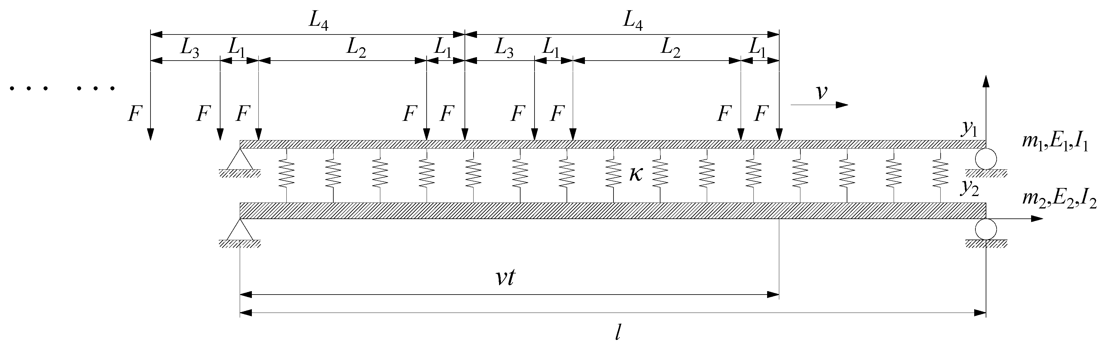
2.2. Expression of Fourier Series of Successive Moving Loads

Through unfolding P k ( t ) with Fourier series,
P k ( t ) = a 0 + j = 1 [ a j cos ( j θ t ) + b j sin ( j θ t ) ]
where loading frequency θ = 2 π v / ( l + d N ) ; d N is the total length of load series.
By solving various coefficients of Fourier series in Equation (24):
a 0 = 1 T τ τ + T P k ( t ) d t
a j = 2 T τ τ + T P k ( t ) cos ( j θ t ) d t
b j = 2 T τ τ + T P k ( t ) sin ( j θ t ) d t
where T = v / ( l + d N ) , τ can be assigned to any value and is usually set at τ = 0 or τ = T 2 to help in calculations.
By substituting Equation (11) into Equations (25)–(27),
a 0 = [ 1 cos ( ξ k l ) ] ξ k ( l + d N ) i = 1 N F i
a j = v i = 1 N F i l + d N { cos [ ξ k l + j θ l v + j θ t i ] cos ( j θ t i ) ξ k v + j θ + cos [ ξ k l j θ l v j θ t i ] cos ( j θ t i ) ξ k v j θ }
b j = v i = 1 N F i l + d N { sin [ ξ k l j θ l v j θ t i ] + sin ( j θ t i ) ξ k v j θ sin [ ξ k l + j θ l v + j θ t i ] sin ( j θ t i ) ξ k v + j θ }

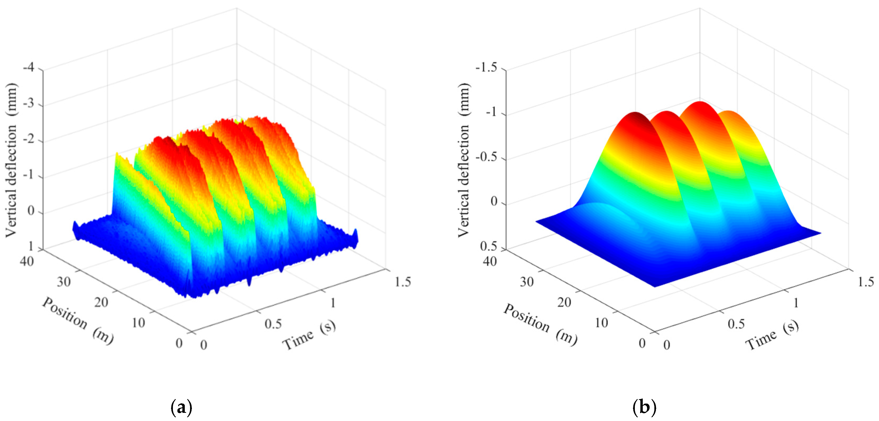
2.3. Dynamic Response of Double-Beam Model Under Load Series

By using Duhamel’s integral to solve Equation (19), the generalized-coordinates solution with zero initial conditions can be obtained as follows:
q n , k s ( t ) = 1 M n , k ω n , k 0 t P n , k ( τ ) sin [ ω n , k ( t τ ) ] d τ
By substituting Equations (24)–(30) into Equation (31),
q n , k s ( t ) = ϕ k 1 , n M n , k ω n , k { a 0 [ 1 cos ω n , k t ] ω n , k + j = 1 [ 1 2 a j [ cos ( j θ t ) cos ( ω n , k t ) j θ ω n , k + cos ( j θ t ) cos ( ω n , k t ) j θ + ω n , k ] + 1 2 b j [ sin ( j θ t ) + sin ( ω n , k t ) j θ + ω n , k sin ( j θ t ) sin ( ω n , k t ) j θ ω n , k ] ] }
The homogeneous solution of Equation (19), considering the initial condition can be expressed as follows:
q n , k 0 ( t ) = q n , k 0 ( 0 ) cos ( ω n , k t ) + q ˙ n , k 0 ( 0 ) ω n , k sin ( ω n , k t )
Using Equation (14):
U k ( 0 ) = n = 1 2 { ϕ k 1 , n ϕ k 2 , n } q n , k 0 ( 0 )
U ˙ k ( 0 ) = n = 1 2 { ϕ k 1 , n ϕ k 2 , n } q ˙ n , k 0 ( 0 )
By pre-multiplying Equations (34) and (35) by { ϕ k 1 , n ϕ k 2 , n } T M k and utilizing weighted orthogonality,
q n , k 0 ( 0 ) = { ϕ k 1 , n ϕ k 2 , n } T M k U k ( 0 ) M n , k
q ˙ n , k 0 ( 0 ) = { ϕ k 1 , n ϕ k 2 , n } T M k U ˙ k ( 0 ) M n , k
When a simply supported double-beam system has zero initial conditions, using Equation (5),
U n , k ( 0 ) = 0 L y n ( x , 0 ) sin ( ξ k x ) d x = 0
U ˙ n , k ( 0 ) = 0 L y ˙ n ( x , 0 ) sin ( ξ k x ) d x = 0
By simultaneously solving Equations (36)–(39),
q n , k 0 ( t ) = 0
Thus, the general solution of Equation (19) with zero initial conditions can be expressed as follows:
q n , k ( t ) = q n , k s ( t ) + q n , k 0 ( t ) = ϕ k 1 , n M n , k ω n , k { a 0 [ 1 cos ω n , k t ] ω n , k + j = 1 [ 1 2 a j [ cos ( j θ t ) cos ( ω n , k t ) j θ ω n , k + cos ( j θ t ) cos ( ω n , k t ) j θ + ω n , k ] + 1 2 b j [ sin ( j θ t ) + sin ( ω n , k t ) j θ + ω n , k sin ( j θ t ) sin ( ω n , k t ) j θ ω n , k ] ] }
By substituting Equations (14) and (41) into Equation (6), the dynamic response of the double-beam model under load series can be obtained as follows:
y = 2 l k = 1 Γ k { q k } sin ξ k x
where y = { y 1 , y 2 } T .

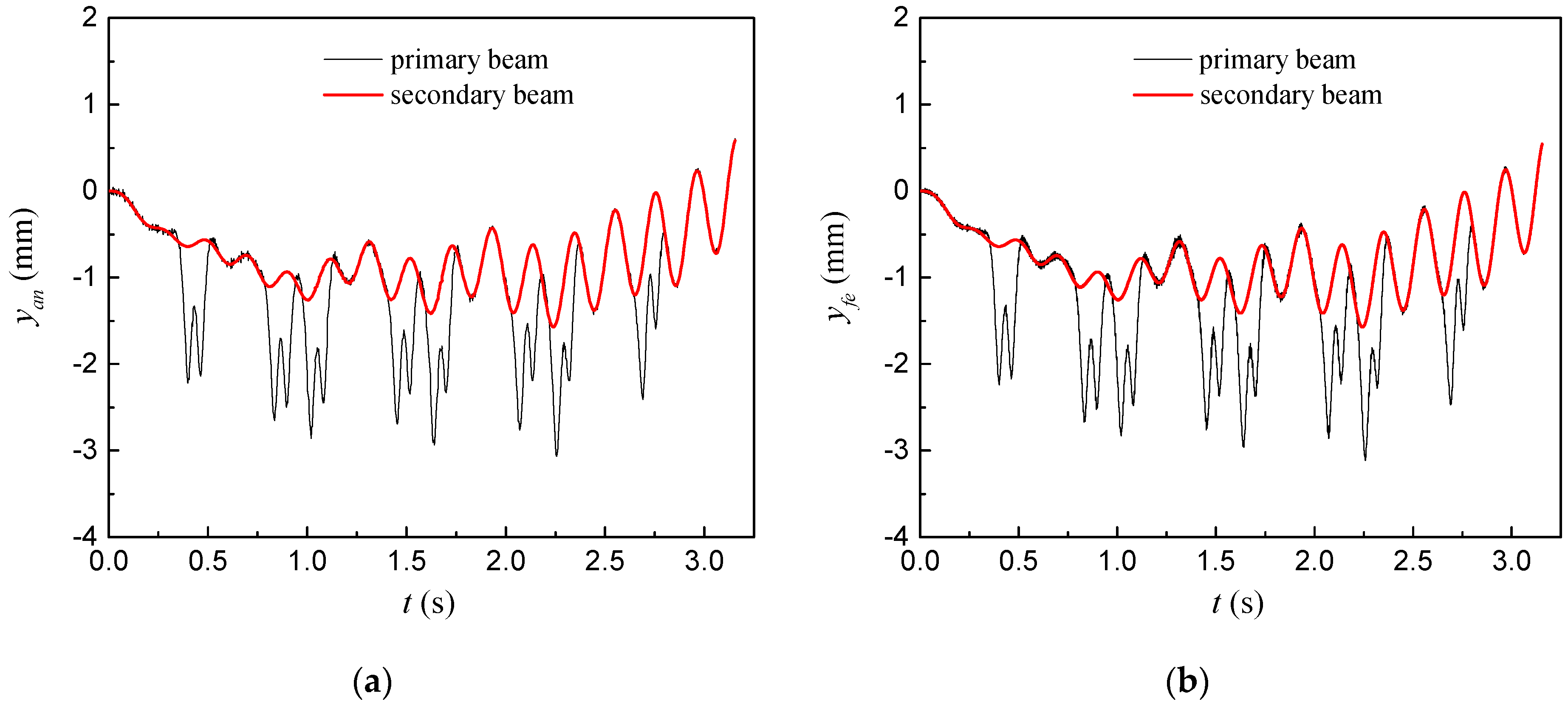
3. Analysis of Calculation Examples

To validate the analytical calculation method proposed in this paper, a simply supported bridge-rail system under the moving loads of four motor car groups was considered as an example, and the analytical calculation method proposed in this paper and ANSYS finite-element numerical method were used to calculate its dynamic response. The simply supported bridge-rail system can be simplified as a simply supported double-beam, and the rail fasteners can be simulated with springs in interlaminar distribution. The specific parameters of the simply supported double-beam system are as follows: length of beams l = 32   m ; length of springs is 1m; damping ratio is 0; primary beam: elastic modulus E 1 = 2.06 × 10 5   MPa , horizontal moment of inertia I 1 = 3.217 × 10 5   m 4 , mass per unit length m 1 = 60   kg / m ; secondary beam: elastic modulus E 2 = 3.5 × 10 4   MPa , horizontal moment of inertia I 2 = 10.42   m 4 , mass per unit length m 2 = 36,000   kg / m ; spring stiffness κ = 6 × 10 7   N / m . As shown in Figure 2, four load-groups contain four moving loads, where load F = 160   kN , distance of load L 1 = 2.5   m , L 2 = 14.875   m , L 3 = 4.9   m , L 4 = 24.775   m .

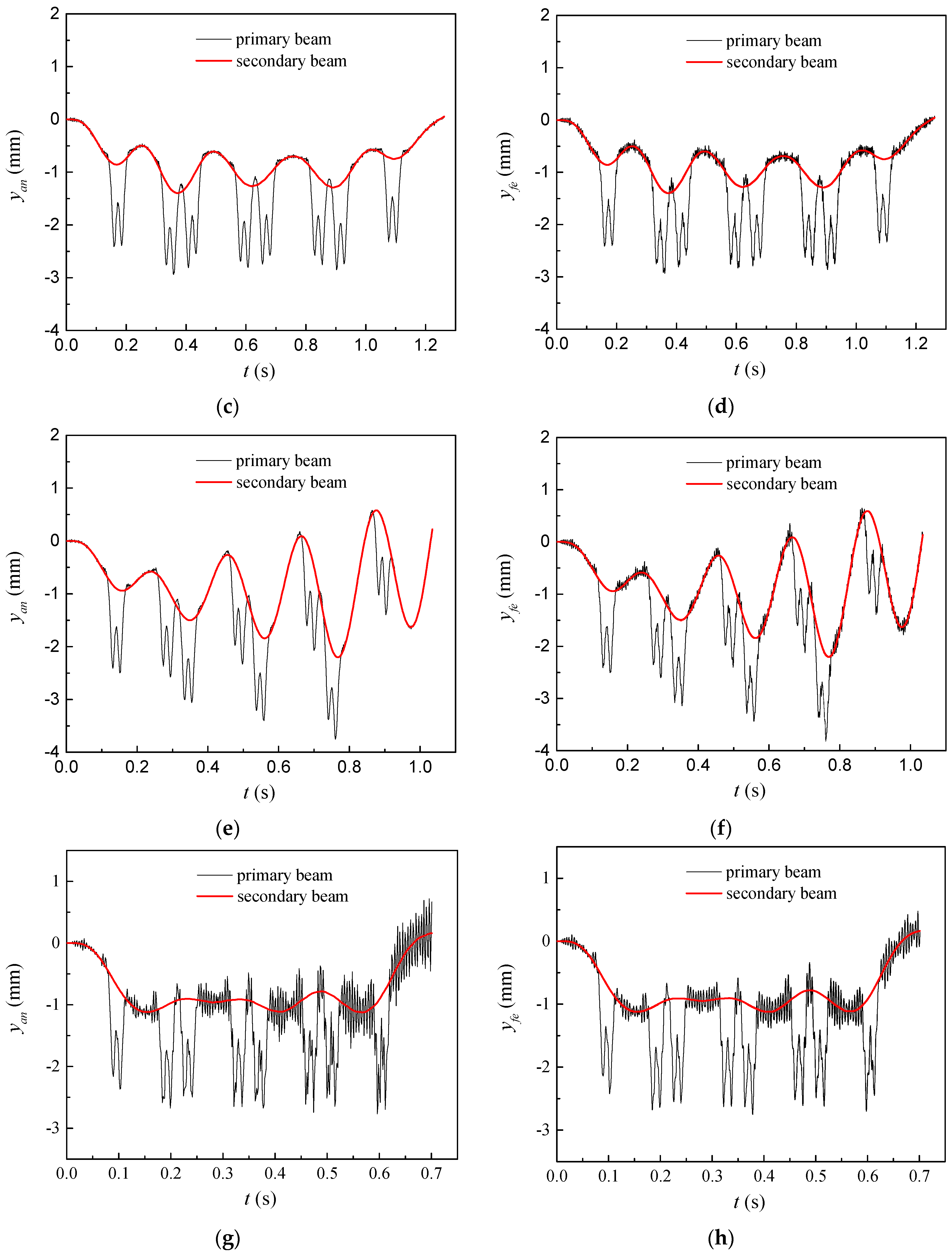
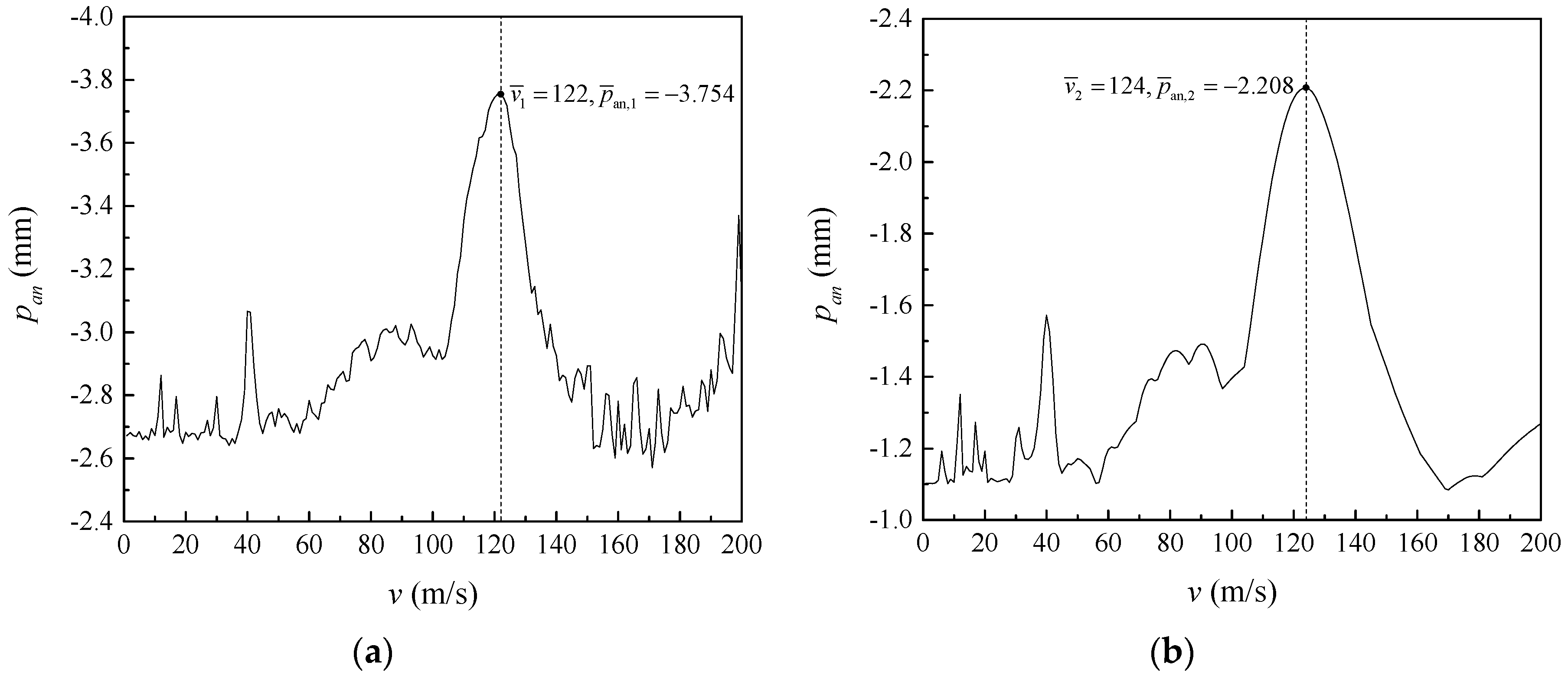
3.1. Effect of Speed of Loads on Dynamic Response of Double-Beam System

To better understand the overall vibration properties of a simply supported double-beam system, the speed of loads was set at v = 100   m / s , and a 3D dynamic graph of vertical deflection of the simply supported double-beam system within the entire span scope was plotted under a load series, as shown in Figure 3.
With the movement of loads, the amplitude of dynamic deflection of the simply supported double-beam system changed constantly; the vertical dynamic deflection of secondary beam at any moment showed an approximately symmetric distribution relative to the midspan position and had only one extreme value in the vicinity of the midspan. The dynamic deflection distribution of the primary beam at any moment was related to the position of the action point of the successive moving loads, and its dynamic deflection showed several extreme values, all emerging at the action point of the successive moving loads. The dynamic deflection of the primary and secondary beams reached their maximum values near the midspan. Considering that this characteristic was not related to the movement position of the load series, the following analyses uniformly used the dynamic deflection response of the midspan.
The analytical calculation method proposed in this paper and the ANSYS finite-element numerical method were used to calculate the dynamic response of the simply supported double-beam system under a load series of four different moving speeds (40 m/s, 100 m/s, 122 m/s, and 180 m/s), and the calculation results of the two methods were compared in terms of the time-history curves and peaks of dynamic deflection response of the midspan. The comparison results are shown in Figure 4 and Table 1 (where y a n and y f e are the calculation results of dynamic deflection response of midspan obtained by the analytical method proposed in this paper and ANSYS finite-element numerical method, respectively; p a n and p f e are the calculation results of peak deflection of midspan obtained from the analytical method proposed in this paper and ANSYS finite-element numerical method, respectively; e p = ( p a n p f e ) / p f e is the calculation error of peak deflection of midspan between the two methods); λp is the ratio of peak dynamic deflection response of midspan of the primary beam to that of the secondary beam. As shown in Figure 4 and Table 1, under a load series of multiple different speeds, the analytical calculation results of time-history curves and peaks of dynamic deflection response of the midspan for the simply supported double-beam system were consistent with the calculation results obtained from the ANSYS finite-element numerical method, thus demonstrating the rationality of the analytical calculation method proposed in this paper. Compared with the secondary beam, the primary beam had a significantly increased peak dynamic deflection response and a high-frequency component in the time-history curve of the dynamic deflection response of the midspan. Under the four speeds, λp values were 1.950, 2.093, 1.706, and 2.467; the peak dynamic deflection responses of the midspan of the primary and secondary beams did not increase with the increase in the speed of the loads, indicating that the simply supported double-beam system under successive moving loads had critical speeds.
Figure 5 shows the relationship between the peak deflection of midspan p a n and speed of loads v for the simply supported double-beam system; p a n , 1 and p a n , 2 are the peak deflections of the midspan of the primary and secondary beams. As shown in Figure 5, the speed of the load-peak deflection of the midspan relationship curve of the primary and secondary beams clearly showed “abrupt increases”, indicating that the simply supported double-beam system had multiple critical speeds under successive moving loads. The peak deflection of the midspan of the primary beam reached its maximum value p ¯ a n , 1 = 3.754   mm at v = 122   m / s , and the peak deflection of the midspan of the secondary beam reached its maximum value p ¯ a n , 2 = 2.208   mm at v = 124   m / s . Assuming the speed corresponding to the maximum peak deflection of the midspan as the dividing speed, the dividing speeds of primary and secondary beams were v ¯ 1 = 122   m / s and v ¯ 2 = 124   m / s , respectively. In the speed of load-peak deflection of the midspan relationship curve of primary and secondary beams, the critical speeds corresponding to the “abrupt increases” were close to each other and should be avoided in engineering practice.

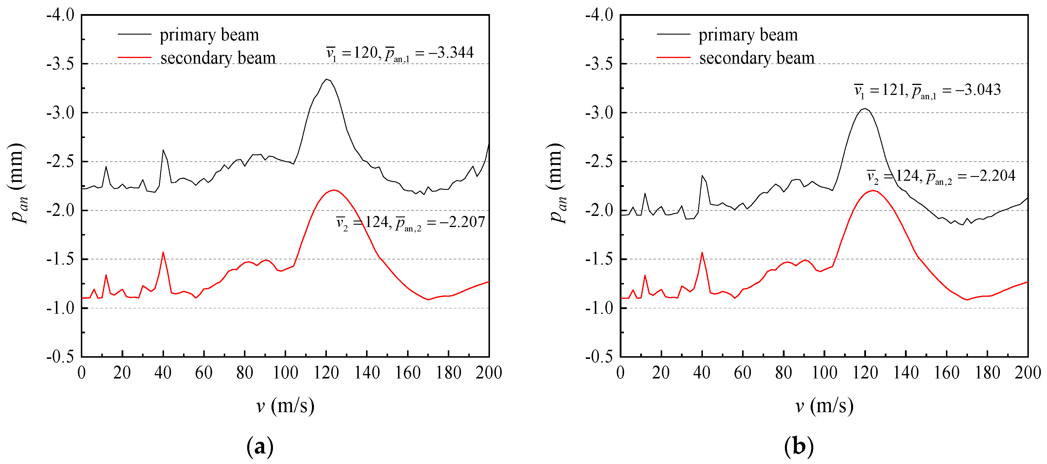
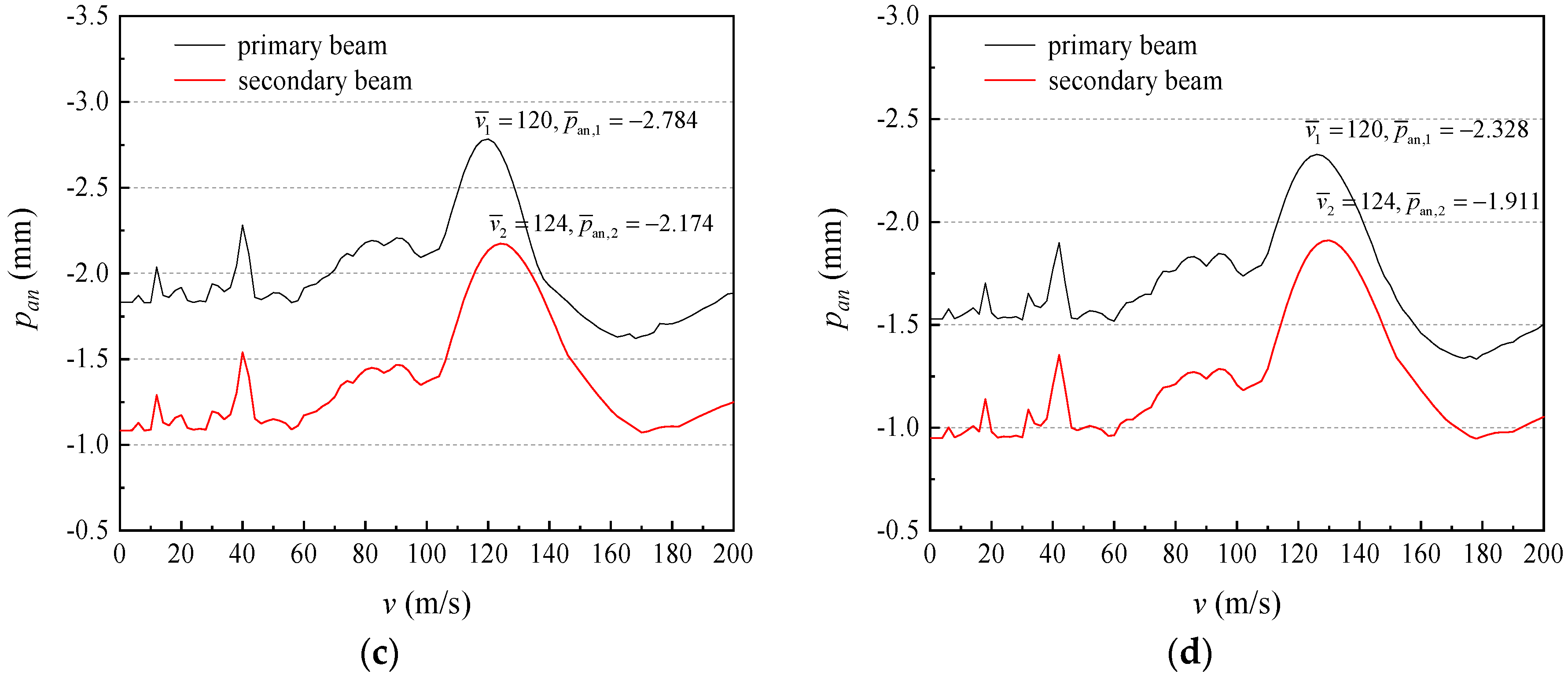
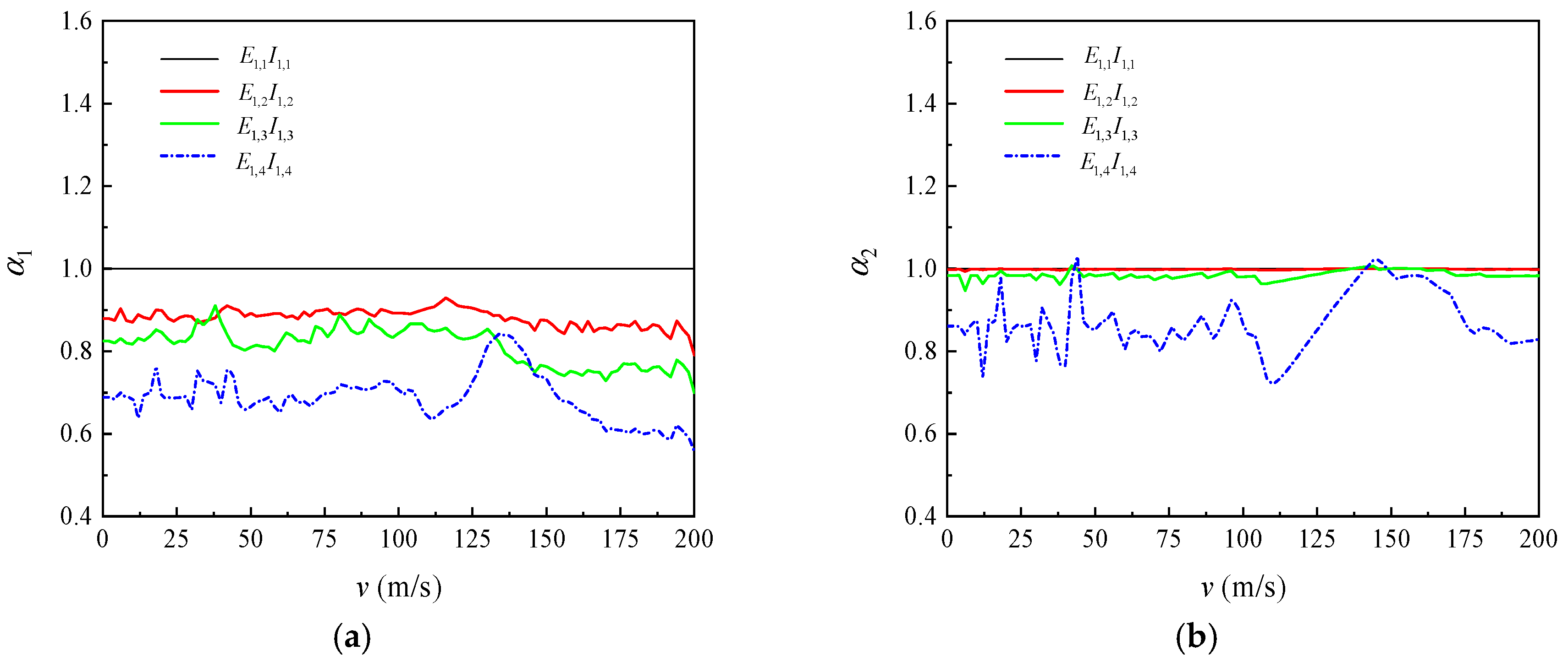
3.2. Effect of Flexural Rigidity on Dynamic Response of Double-Beam System

The effect of four flexural rigidity (EI) of the primary beam (i.e., E 1 , 1 I 1 , 1 = 0.0001 E 2 I 2 , E 1 , 2 I 1 , 2 = 0.001 E 2 I 2 , E 1 , 3 I 1 , 3 = 0.01 E 2 I 2 , and E 1 , 4 I 1 , 4 = 0.1 E 2 I 2 ) on the peak deflection of the midspan of a simply supported double-beam system under successive moving loads was evaluated. The amplification factor of peak deflection of the midspan under different flexural rigidity is defined as follows:
α n | E 1 I 1 = E 1 , i I 1 , i = p a n , n | E 1 I 1 = E 1 , i I 1 , i p a n , n | E 1 I 1 = E 1 , 1 I 1 , 1   ( n = 1 , 2 ; i = 1 , 2 , 3 , 4 )
Figure 6 and Figure 7 show the relationship between peak deflection of the midspan of a simply supported double-beam system and speed of loads under different flexural rigidity. Under flexural rigidity, the dividing speeds v ¯ 1 and v ¯ 2 of the simply supported double-beam system both changed slightly; therefore, the effect of flexural rigidity on the dividing speed of the simply supported double-beam system could be neglected. For the primary beam, the amplification factor of peak deflection of the midspan and maximum value of the peak deflection of the midspan p ¯ a n , 1 both significantly decreased with the increase in flexural rigidity. For the secondary beam, the amplification factor α 1 of peak deflection of the midspan α 2 and maximum value of peak deflection of the midspan p ¯ a n , 2 both slightly decreased with the increase in flexural rigidity. For different situations of the two beams, it was mainly because the primary and secondary beams had a relatively significant difference in the flexural rigidity change, mainly exerted by the dynamic response of the primary simply supported beam.

4. Conclusions

A dynamic analysis model was established for a simply supported double-beam system under successive moving loads. Based on finite sin-Fourier transform and finite sin-Fourier inverse transform, the analytical expression of dynamic response of the simply supported double-beam system under successive moving loads was deduced. Considering the dynamic response of a simply supported double-beam system under train loads, the results of the analytical method were compared with those obtained from the general FEM software ANSYS. The following conclusions are drawn:
Under a load series of multiple different moving speeds, the analytical calculation results of the time-history curve of deflection of the midspan of the double-beam system were consistent with the calculation results obtained from the ANSYS, thus demonstrating the rationality of the analytical calculation method proposed in this paper. The analytical calculation method proposed in this paper has a clear concept, convenient for manual calculation, and provides a theoretical foundation for further engineering applications of simply supported double-beam systems under successive moving loads.
The simply supported double-beam system under a load series uniformly showed the maximum value of dynamic deflection response in the vicinity of the midspan, and the peak deflection of the midspan moving speed of the load series relationship curve of the system showed several “abrupt increases”, indicating that the simply supported double-beam system had multiple critical speeds under a load series.
In the simply supported double-beam system under a load series, the critical and dividing speeds of the primary and secondary beams were close to each other, respectively, and should be avoided in engineering practice. The deflection of the primary beam is suppressed by the secondary beam.
For the primary beam of the simply supported double-beam system, the amplification factor of the peak deflection of midspan α 1 and maximum value of peak deflection of midspan p ¯ a n , 1 both significantly decreased with the increase in flexural rigidity; however, for the secondary beam, the effect of speed of loads on the amplification factor of peak deflection of midspan α 2 was not clear.

Author Contributions

The authors have contributed equally to this work. L.J. and Y.Z. conceived and prepared original draft; Y.F. and Z.T. contributed analysis tools; L.J. and W.Z. analyzed the data; Y.F. and W.Z. reviewed.

Funding

This research was financially supported by the National Natural Science Foundations of China (Grant Number 51408449 and 51778630), and the Fundamental Research Funds for the Central Universities of Central South University (Grant Number 2018zzts189).

Conflicts of Interest

The authors declare no conflict of interest.

References

  1. Zhang, D.Y.; Jia, H.Y.; Zheng, S.X.; Xie, W.C.; Pandey, M.D. A highly efficient and accurate stochastic seismic analysis approach for structures under tridirectional nonstationary multiple excitations. Comput. Struct. 2014, 145, 23–35. [Google Scholar] [CrossRef]
  2. Luo, N.; Jia, H.; Liao, H. Coupled wind-induced responses and equivalent static wind loads on long-span roof structures with the consistent load–response–correlation method. Adv. Struct. Eng. 2018, 21, 71–81. [Google Scholar] [CrossRef]
  3. Museros, P.; Moliner, E.; Martínez-Rodrigo, M.D. Free vibrations of simply-supported beam bridges under moving loads: Maximum resonance, cancellation and resonant vertical acceleration. J. Sound Vib. 2013, 332, 326–345. [Google Scholar] [CrossRef]
  4. Yau, J.D.; Frýba, L. Response of suspended beams due to moving loads and vertical seismic ground excitations. Eng. Struct. 2007, 29, 3255–3262. [Google Scholar] [CrossRef]
  5. Kurihara, M.; Shimogo, T. Stability of a Simply-Supported beam subjected to randomly spaced moving loads. J. Mech. Des. 1978, 100, 507–513. [Google Scholar] [CrossRef]
  6. Abu-Hilal, M. Vibration of beams with general boundary conditions due to a moving random load. Arch. Appl. Mech. 2003, 72, 637–650. [Google Scholar] [CrossRef]
  7. Kumar, C.P.S.; Sujatha, C.; Shankar, K. Vibration of simply supported beams under a single moving load: A detailed study of cancellation phenomenon. Int. J. Mech. Sci. 2015, 99, 40–47. [Google Scholar] [CrossRef]
  8. Chen, Y.H.; Sheu, J.T. Beam on Viscoelastic Foundation and Layered Beam. J. Eng. Mech. 1995, 121, 340–344. [Google Scholar] [CrossRef]
  9. Vu, H.V.; Ordonez, A.M.; Kaenopp, B.H. Vibration of a double-beam system. J. Sound Vib. 2000, 229, 807–822. [Google Scholar] [CrossRef]
  10. Rusin, J.Ł.; Śniady, P.Ł.; Śniady, P. Vibrations of double-string complex system under moving forces. Closed solutions. J. Sound Vib. 2011, 330, 404–415. [Google Scholar] [CrossRef]
  11. Wu, Y.; Gao, Y. Analytical solutions for simply supported viscously damped Double-Beam system under moving harmonic loads. J. Eng. Mech. 2015, 141, 4015004. [Google Scholar] [CrossRef]
  12. Oniszczuk, Z. Transverse vibrations of elastically connected double-string complex system—Part I: Free vibrations. J. Sound Vib. 2000, 232, 355–366. [Google Scholar] [CrossRef]
  13. Oniszczuk, Z. Forced transverse vibrations of an elastically connected complex simply supported double-beam system. J. Sound Vib. 2003, 264, 273–286. [Google Scholar] [CrossRef]
  14. Li, J.; Hua, H. Spectral finite element analysis of elastically connected double-beam systems. Finite Elem. Anal. Des. 2007, 43, 1155–1168. [Google Scholar] [CrossRef]
  15. Zhang, Y.Q.; Lu, Y.; Ma, G.W. Effect of compressive axial load on forced transverse vibrations of a double-beam system. Int. J. Mech. Sci. 2008, 50, 299–305. [Google Scholar] [CrossRef]
  16. Palmeri, A.; Adhikari, S. A Galerkin-type state-space approach for transverse vibrations of slender double-beam systems with viscoelastic inner layer. J. Sound Vib. 2011, 330, 6372–6386. [Google Scholar] [CrossRef] [Green Version]
  17. Stojanović, V.; Kozić, P. Forced transverse vibration of Rayleigh and Timoshenko double-beam system with effect of compressive axial load. Int. J. Mech. Sci. 2012, 60, 59–71. [Google Scholar] [CrossRef]
  18. Pavlović, R.; Kozić, P.; Pavlović, I. Dynamic stability and instability of a double-beam system subjected to random forces. Int. J. Mech. Sci. 2012, 62, 111–119. [Google Scholar] [CrossRef]
  19. Li, Y.X.; Hu, Z.J.; Sun, L.Z. Dynamical behavior of a double-beam system interconnected by a viscoelastic layer. Int. J. Mech. Sci. 2016, 105, 291–303. [Google Scholar] [CrossRef]
  20. Li, Y.X.; Sun, L.Z. Transverse vibration of an undamped elastically connected Double-Beam system with arbitrary boundary conditions. J. Eng. Mech. 2016, 142, 4015070. [Google Scholar] [CrossRef]
  21. Wu, Y.; Gao, Y. Dynamic response of a simply supported viscously damped double-beam system under the moving oscillator. J. Sound Vib. 2016, 384, 194–209. [Google Scholar] [CrossRef]
  22. Murmu, T.; Adhikari, S. Nonlocal transverse vibration of double-nanobeam-systems. J. Appl. Phys. 2010, 108, 83514. [Google Scholar] [CrossRef] [Green Version]
  23. Khaniki, H.B. On vibrations of nanobeam systems. Int. J. Eng. Sci. 2018, 124, 85–103. [Google Scholar] [CrossRef]
  24. Frank, I.W.; Lončar, M.; Mccutcheon, M.W.; Deotare, P.B. Programmable photonic crystal nanobeam cavities. Opt. Express 2010, 18, 8705–8712. [Google Scholar] [CrossRef]
  25. Murmu, T.; Adhikari, S. Axial instability of double-nanobeam-systems. Phys. Lett. A 2011, 375, 601–608. [Google Scholar] [CrossRef]
  26. şimşek, M. Nonlocal effects in the forced vibration of an elastically connected double-carbon nanotube system under a moving nanoparticle. Comput. Mater. Sci. 2011, 50, 2112–2123. [Google Scholar] [CrossRef]
  27. Cheng, Y.S.; Au, F.T.K.; Cheung, Y.K. Vibration of railway bridges under a moving train by using bridge-track-vehicle element. Eng. Struct. 2001, 23, 1597–1606. [Google Scholar] [CrossRef]
  28. Biondi, B.; Muscolino, G.; Sofi, A. A substructure approach for the dynamic analysis of train-track-bridge system. Comput. Struct. 2005, 83, 2271–2281. [Google Scholar] [CrossRef]
  29. Lou, P. A vehicle-track-bridge interaction element considering vehicle’s pitching effect. Finite Elem. Anal. Des. 2005, 41, 397–427. [Google Scholar] [CrossRef]
  30. Lou, P.; Yu, Z.; Au, F.T.K. Rail-bridge coupling element of unequal lengths for analysing train-track-bridge interaction systems. Appl. Math. Model. 2012, 36, 1395–1414. [Google Scholar] [CrossRef]
  31. Jia, H.Y.; Zhang, D.Y.; Zheng, S.X.; Xie, W.C.; Pandey, M.D. Local site effects on a high-pier railway bridge under tridirectional spatial excitations: Nonstationary stochastic analysis. Soil Dyn. Earthq. Eng. 2013, 52, 55–69. [Google Scholar] [CrossRef]
  32. Zhang, F.L.; Ni, Y.C.; Au, S.K.; Lam, H.F. Fast Bayesian approach for modal identification using free vibration data, Part I—Most probable value. Mech. Syst. Signal Process. 2016, 70–71, 209–220. [Google Scholar] [CrossRef]
  33. Hussein, M.F.M.; Hunt, H.E.M. Modelling of floating-slab tracks with continuous slabs under oscillating moving loads. J. Sound Vib. 2006, 297, 37–54. [Google Scholar] [CrossRef]
  34. Xin, T.; Gao, L. Reducing slab track vibration into bridge using elastic materials in high speed railway. J. Sound Vib. 2011, 330, 2237–2248. [Google Scholar] [CrossRef] [Green Version]
  35. Lai, Z.; Jiang, L.; Zhou, W. An analytical study on dynamic response of multiple simply supported beam system subjected to moving loads. Shock Vib. 2018, 2018, 2149251. [Google Scholar] [CrossRef]
Figure 1. Double-beam system under successive moving loads.
Applsci 09 02162 g001
Figure 2. The primary-secondary beam system under moving load-groups.
Applsci 09 02162 g002
Figure 3. The 3D dynamic graphs of vertical deflection of a simply supported double-beam system for: (a) primary beam; (b) secondary beam.
Applsci 09 02162 g003
Figure 4. The response of the beams obtained by different method: (a,b) v 1 = 40   m / s ; (c,d) v 2 = 100   m / s ; (e,f) v 3 = 122   m / s ; (g,h) v 4 = 180   m / s .
Applsci 09 02162 g004aApplsci 09 02162 g004b
Figure 5. The max response versus the speed for: (a) primary beam; (b) secondary beam.
Applsci 09 02162 g005
Figure 6. The max response versus the speed: (a) E 1 , 1 I 1 , 1 = 0.0001 E 2 I 2 ; (b) E 1 , 2 I 1 , 2 = 0.001 E 2 I 2 ; (c) E 1 , 3 I 1 , 3 = 0.01 E 2 I 2 ; (d) E 1 , 4 I 1 , 4 = 0.1 E 2 I 2 .
Applsci 09 02162 g006aApplsci 09 02162 g006b
Figure 7. The magnification factor under different flexural rigidity for: (a) primary beam; (b) secondary beam.
Applsci 09 02162 g007
Table 1. Time-history curve peak of midspan displacement (unit: mm).
v   ( m / s ) Layer p a n p f e e p
40Primary beam−3.067−3.112−1.46%
Secondary beam−1.572−1.5710.06%
λp1.9501.981
100Primary beam−2.922−2.933−0.40%
Secondary beam−1.396−1.399−0.23%
λp2.0932.096
122Primary beam−3.754−3.815−1.60%
Secondary beam−2.201−2.2000.04%
λp1.7061.734
180Primary beam−2.769−2.7540.53%
Secondary beam−1.122−1.1210.07%
λp2.4672.456

