Article

Improved Altitude Control Algorithm for Quadcopter Unmanned Aerial Vehicles

Faculty of Mechanical and Aerospace Engineering, Sejong University, Seoul 143-747(05006), Korea
*
Author to whom correspondence should be addressed.
Appl. Sci. 2019, 9(10), 2122; https://doi.org/10.3390/app9102122
Submission received: 25 April 2019 / Revised: 20 May 2019 / Accepted: 20 May 2019 / Published: 24 May 2019
(This article belongs to the Section Mechanical Engineering)

Abstract

:
Quadcopter unmanned aerial vehicles continue to play important roles in several applications and the improvement of their control performance has been explored in a great number of studies. In this paper, we present an altitude control algorithm for quadcopters that consists of a combination of nonlinear and linear controllers. The smooth transition between the nonlinear and linear modes are guaranteed through controller gains that are obtained based on mathematical analysis. The proposed controller takes advantage and addresses some known shortcomings of the conventional proportional–integral–derivative control method. The algorithm is simple to implement, and we prove its stability through the Lyapunov theory. By prescribing certain flight conditions, we use numerical simulations to compare the control performance of our control method to that of a conventional proportional–derivative–integral approach. Furthermore, we use a DJI-F450 drone equipped with a laser ranging sensor as the experimental quadcopter platform to evaluate the performance of our new controller in real flight conditions. Numerical simulation and experimental results demonstrate the effectiveness of the proposed algorithm.

Graphical Abstract

1. Introduction

In recent decades, unmanned aerial vehicles (UAVs) have gained popularity in the scientific community due to their numerous advantages such as high maneuverability, diverse applicability, reliability, and economy. UAVs are used in a broad range of applications such as scientific research, civil engineering, military applications, aerial mapping, search and rescue operations, and risk zone inspection [1,2,3,4]. Quadcopters are an important class of UAVs that are superior in many ways: they have a simple structure, are quick to manufacture, and are inexpensive [4,5]. Controlling their position, in general, and altitude, in particular, has been the subject of numerous studies [6,7,8,9,10,11,12,13,14,15,16,17,18,19,20,21,22,23] with ever more advanced algorithms having been proposed to address the quadcopter control problem.

1.1. Related Works

Many applications of quadcopters in the real world have been discussed in recent years. The most widely mentioned topics include autonomous landing on moving platforms [6,7,8,9], precision landing for autonomous docking and wireless self-charging system [10,11], and autonomous delivery tasks [12,13,14]. These applications are all, somehow, based on a reliable altitude controller. Therefore, designing an altitude controller with superior performance is one of the most common and important efforts that researchers all around the world are nowadays undertaking.
To that end, several papers have addressed the altitude control problem in the literature. Santos et al. [15] presented an algorithm to accomplish quadcopter trajectory tracking tasks by controlling the altitude through an adaptive dynamic controller that was capable of dealing with uncertainties in model parameters. Jayakrishnan [16] and Xiong et al. [17] used the sliding mode control (SMC) technique to control the horizontal position and attitude while also providing a significant improvement of altitude control. In other studies [18,19,20], the second order SMC method was also used to improve quadcopter altitude control performances. Yet another method was presented by Muliadi et al. [21], where the authors proposed a neural network approach to control UAV altitude dynamics. The results obtained with this method were verified through comparisons with a conventional proportional–integral–derivative (PID) control system. However, these approaches [15,16,17,18,19,20,21] have a common disadvantage in that the SMC technique generates a high chattering control signal method which reduces the lifetime of the entire system.
Although several control methods have been proposed in the literature, PID control has become the most widely used technique in a variety of applications all over the world because it is simple and easy to design and typically delivers a satisfactory performance. The PID approach was used in many studies [22,23,24,25,26,27,28] to achieve not only quadcopter altitude control, but also attitude stabilization and horizontal position control. In recent studies [29,30,31,32], the authors proposed the use of a multi-loop control architecture (i.e., inner-loop and outer-loop) to control quadcopters in specific applications. The outer-loop controllers were designed in different ways while the inner-loop controllers were all implemented using the PID control law.
Nevertheless, the conventional PID controller has several limitations. First, their fixed gains limit system performance over a wider operational range. When the required range of operation is large, the conventional PID controller is prone instability, because the nonlinearities in the system cannot be properly dealt with. Second, as conventional PIDs are based on a linear model, their performance may suffer in a nonlinear system like a quadcopter. Several studies have attempted to overcome these shortcomings. Phi et al. [33] presented a gain scheduling PID controller which determines the PID gains by linearly adjusting the gain as a function of tracking errors. In another approach [34], the authors used a pickup table to schedule the PID gains in a quadrotor fault tolerant control task. Both methods were able to improve the control performance under different operating conditions. However, it is still a linear control law which means that it may not perform well in non-linear systems. Further, scheduling the gains results in discontinuous transitions which may result in sudden jerks or oscillations. A quadcopter self-tuning fuzzy PID controller where the gains are tuned nonlinearly through fuzzy logic have been proposed to address this problem [35]. Goodarzi et al. [36] introduced a nonlinear PID control to achieve asymptotic system stability under the presence of uncertainties. Another way to cope with the difficulties in control of a nonlinear system is to represent the dynamical system by the Takagi–Sugeno (T–S) fuzzy model [37]. Based on this approach, Liu et al. [38] addressed the problem of finite-time stability and stabilization for a class of nonlinear systems with time-varying delay. However, both the T–S fuzzy and linear parameter varying (LPV) approaches [39,40] require considerably greater computational resources compared with a conventional PID controller.
The references indicate that most of the existing methods either are complex to design and implement or require great computational resources. Meanwhile, PID control law appears to play an important role for finding a simple and efficient control method for a variety of systems. Designing a controller that makes use of the inherent advantages of the PID approach while tackling its shortcomings is therefore an important and worthwhile challenge.

1.2. Main Contributions

Motivated by the above observations, in this article, we propose an altitude control algorithm for quadcopter unmanned aerial vehicles. The main advantages of this new method are twofold: (1) while our method inherit the advantages of the PID approach, i.e., it is simple and straightforward, its multi-loop approach ensures that unlike other control algorithms [33,34,35,36,37,38], our controller requires less computational resources and exhibits a smooth performance at all times; and (2) compared to conventional PID controllers, our control algorithm delivers a greatly improved performance with regard to both raising time and error convergence speed.
We use the Lyapunov stability theory to validate the system’s stability. We prescribe a maximum acceleration/deceleration of the vehicle which allows the controller to have the vehicle move at an appropriate acceleration before fast and hard approaching a target. This contributes to a safer and smoother flight performance of both single vehicles performing specific missions [5,14,41,42] and multi-agent systems flying in formation or switching their inter-communication topology [43,44]. For safety reasons, we firstly evaluate the performance of our new controller with numerical simulations and then we will conduct experimental flights to demonstrate the effectiveness of the proposed algorithm in real flight conditions.

1.3. Organization

The remainder of this paper is organized as follows: Section 2 presents the dynamical quadcopter model and Section 3 the control algorithm while the numerical simulation and experimental demonstration results and their discussions are provided in Section 4, before ending with the main conclusions.

2. Preliminaries

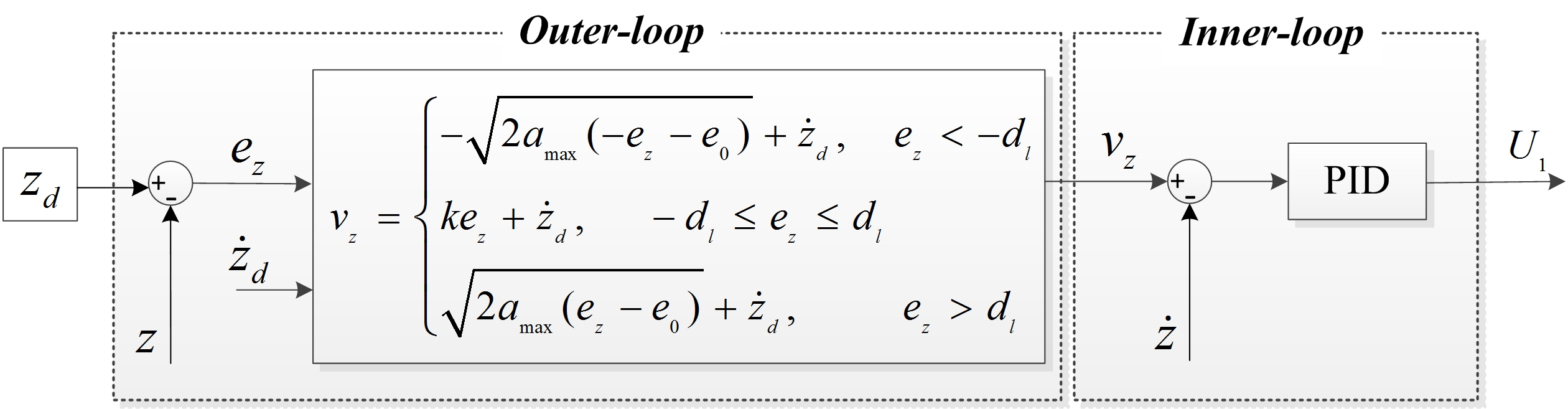
2.1. Quadcopter Dynamics Model

Here, we briefly summarize the quadcopter dynamics model as it has already been presented previously [45,46].
Let ϕ ,   θ , and ψ denote the three Euler angles roll, pitch, and yaw, respectively, where, | ϕ | < π / 2 , | θ | < π / 2 , and | ψ | π (see Figure 1). The symbols x , y , and z respectively represent the position of the quadcopter along the x , y , and z axes in an earth-fixed frame {E}. J x ,   J y , and J z denote the moments of inertia along the x , y , and z axes, respectively; m represents the mass, l the arm length of the vehicle, and g the gravitational acceleration. The quadcopter dynamics model can be described as follows [45,46]:
{ ϕ ¨ = ( J y J z J x ) θ ˙ ψ ˙ + l J x U 2 θ ¨ = ( J z J x J y ) ϕ ˙ ψ ˙ + l J y U 3 ψ ¨ = ( J x J y J z ) ϕ ˙ θ ˙ + 1 J z U 4 x ¨ = 1 m ( cos ϕ sin θ cos ψ + sin ϕ sin ψ ) U 1 y ¨ = 1 m ( cos ϕ sin θ sin ψ sin ϕ cos ψ ) U 1 z ¨ = g 1 m ( cos ϕ cos θ ) U 1
where U i ( i =   1 ,   2 ,   3 ,   4 ) denotes the control inputs which are:
{ U 1 = F 1 + F 3 + F 2 + F 4 U 2 = F 4 F 2 U 3 = F 3 F 1 U 4 = C d ( F 1 + F 3 F 2 F 4 )
where F i = C t Ω i 2 denotes the thrust force generated by motor i ; Ω i is the speed of motor i ; C t and C d are the thrust and drag coefficients, respectively.

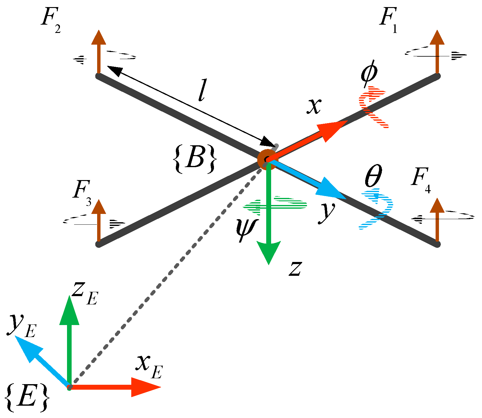
2.2. Quadcopter Control Scheme

The overall control scheme consists of position and attitude controllers (Figure 2). Conventional PID controllers are used for both horizontal (x- and y-) position control and attitude control while a new algorithm is proposed for altitude control. It is worth noting that our new algorithm can also be used for horizontal position control.

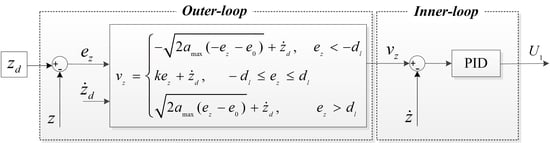
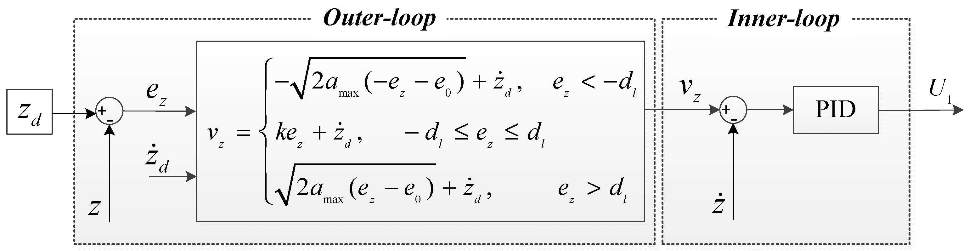
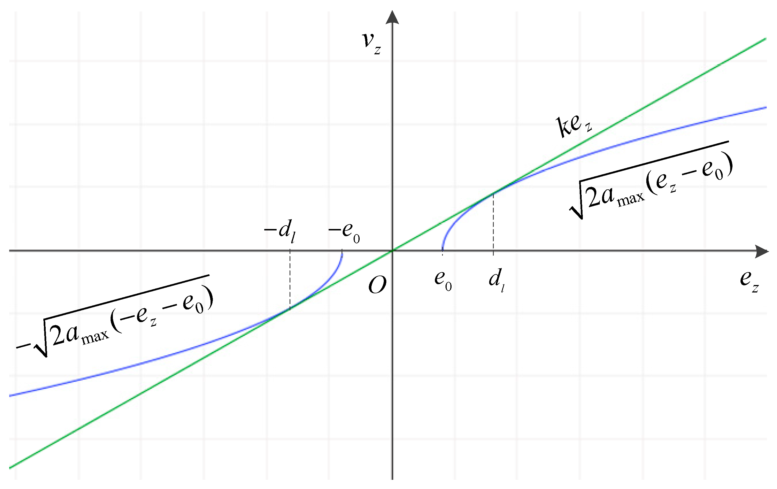
3. Controller Design

The multi-loop PID-PID control scheme for quadcopter altitude control was introduced and verified in some existing studies [28,33,47]. In this section, we present our new altitude control algorithm which also consists of a multi-loop controller, i.e., outer-loop and inner-loop. We derive the outer-loop as a multi-mode (i.e., nonlinear and linear modes) control law while the inner-loop is a PID controller.
Let z d denote the desired attitude, and v z represent the vertical velocity of the vehicle. The altitude tracking error is then given by:
e z = z d z
Then the derivative of e z is:
e ˙ z = z ˙ d v z
A multi-mode control law is chosen for the outer-loop of the altitude controller as:
v z = { 2 a max ( e z e 0 ) + z ˙ d , e z < d l k e z + z ˙ d , d l e z d l 2 a max ( e z e 0 ) + z ˙ d , e z > d l
where, a max is a positive constant which represents the desired maximum acceleration of the vehicle; d l a positive constant at which the line ( Δ ) :   v z = k e z + z ˙ d to be tangential to the curve ( S ) :   v z = { 2 a max ( e z e 0 ) + z ˙ d , e z < d l 2 a max ( e z e 0 ) + z ˙ d , e z > d l ; k ,   e 0 positive constants, and e 0 < d l ; v z the control action which will be fed into the inner-loop (see Figure 3) as a velocity reference [31].
Figure 4 shows v z as a function of e z from Expression (5) corresponding to z ˙ d = 0 . For z ˙ d 0 , the graphs are shifted along the v z axis an amount of z ˙ d without any change of the relations between ( S ) and ( Δ ) . In order for the line ( Δ ) to be tangential to the curve ( S ) at e z = d l , the followings must be satisfied:
{ k e z = 2 a max ( d l e 0 ) k = 2 a max 2 d l e 0
Manipulating (6) yields:
{ d l = a max k 2 e 0 = d l 2
Theorem 1.
If the control law is designed as Expression (3) with the parameters satisfying (6) then the system (1) is asymptotically stable and the tracking error is forced to zero.
Proof. 
Choose a Lyapunov candidate function as:
V = { 2 e z e 0 , e z < d l 1 2 e z 2 , d l e z d l 2 e z e 0 , e z > d l
It is clear that V > 0 ,   e z 0 . We have:
V ˙ = { e ˙ z e z e 0 , e z < d l e ˙ z e z ,     d l e z d l e ˙ z e z e 0 , e z > d l
Substituting (4) into (9) and choosing control laws as (5), we have:
V ˙ = { 2 a max , e z < d l k e z 2 ,     d l e z d l 2 a max , e z > d l
Clearly, we have V ˙ < 0 ,   e z 0 which means that the tracking error, e z , converges to zero as time t . This completes the proof. □
Remark 1.
When e z < d l or e z > d l , the controller generates control actions that follow the curve ( S ) . While this is the case, the slope of ( S ) is smaller than that of ( Δ ) which means that the acceleration is limited, which in turn results in fewer overshoots and vehicle jerks. Whereas, when d l e z d l , the control action follows the line ( Δ ) which has a higher slope. This guarantees that the tracking error converges to zero in a prompt and hard manner.
Remark 2.
When d l e z d l , the proposed controller becomes a proportional-PID (P-PID) control scheme, which implies that the parameter k can be obtained through a conventional PID tuning process. Moreover, at e z = d l and e z = d l , the line ( Δ ) becomes a tangent to the curve ( S ) , resulting in smooth transitions when the controller switches control modes (between nonlinear and linear modes), with regard to both acceleration and velocity.

4. Numerical Simulation, Experimental Results and Discussions

In this section, we demonstrate the effectiveness of the proposed altitude control algorithm. The quadcopter dynamics from Expression (1) are used to verify the stability and advanced performance of our controller. By comparing our new method to a conventional PID controller, we highlight and discuss the effectiveness of the new method.

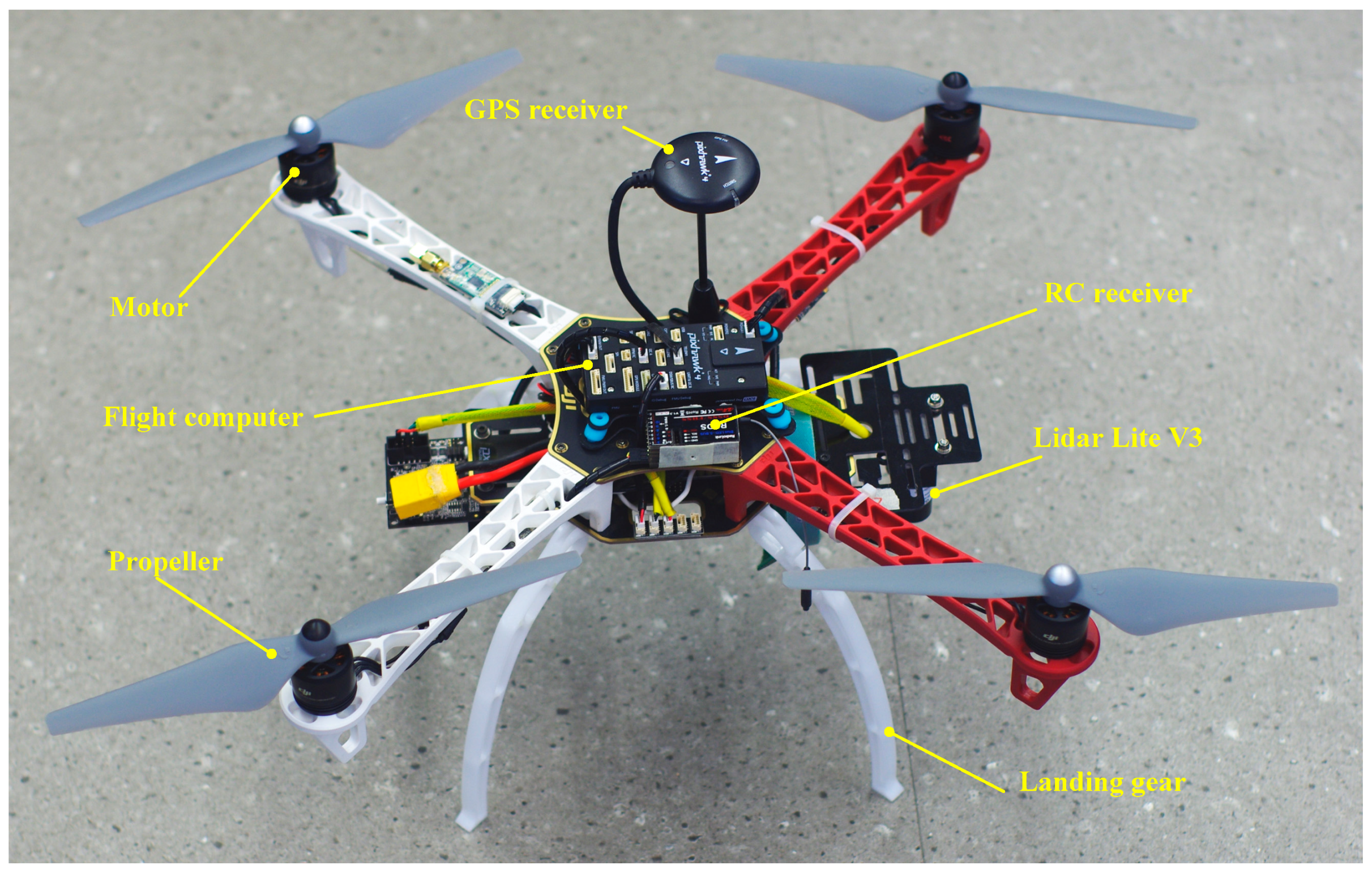
4.1. Experimental Platform Description

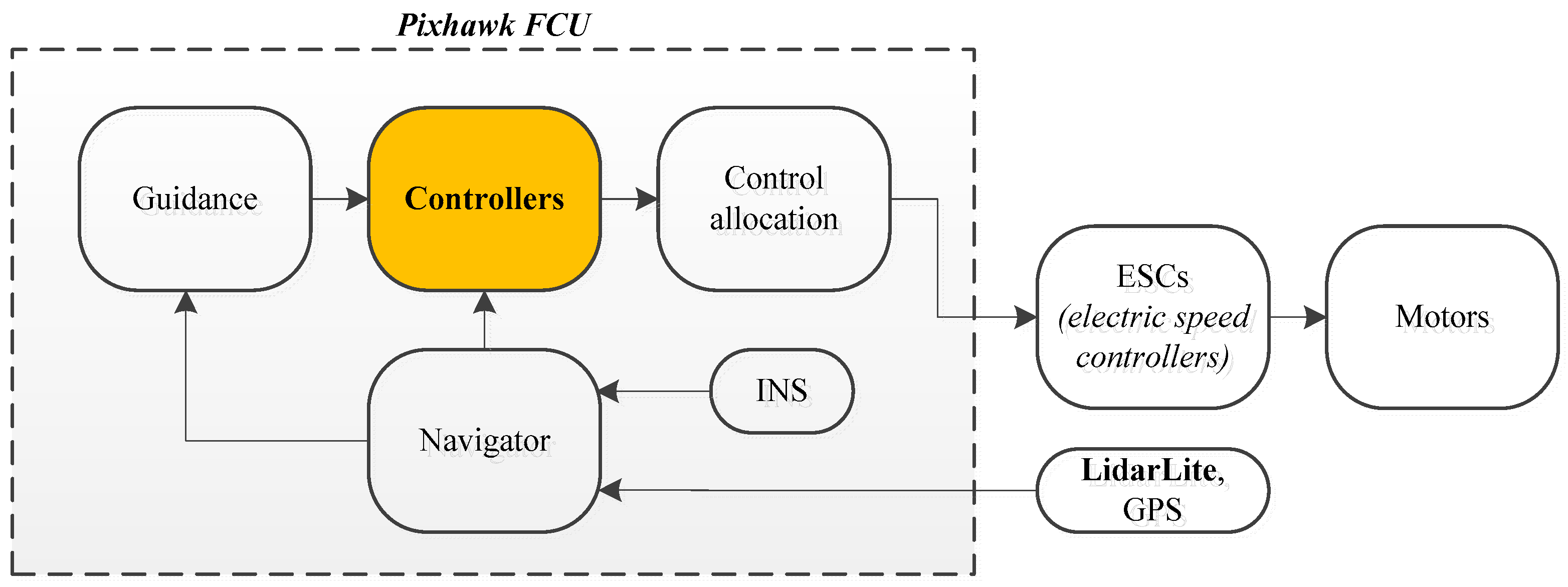
4.1.1. Hardware and Avionics Devices

We use a DJI-F450 quadcopter as the experimental platform (Figure 5) which is operated by an onboard flight computer unit (FCU) Pixhawk [48,49]. The quadcopter attitude and acceleration are provided by an inertial navigation system (INS). We use a commercially available laser ranging sensor LidarLite V3 to measure the altitude and a commercial global positioning system (GPS) receiver to determine the position of the vehicle. Additionally, a power supplying system (including battery, power adapter module), a set of remote control transmitter/receiver for the manual pilot, and a set of radio telemetry transmitter/receiver for ground station monitoring are used. The quadcopter dynamical parameters are listed in Table 1.

4.1.2. Software

We implemented all vehicle altitude, position, and attitude controllers on the Pixhawk FCU running at frequencies of 100 Hz, 100 Hz, and 400 Hz, respectively. The altitude controller gains and reference values for altitude are listed in Table 2. It is worth noting that the horizontal position controller and attitude controller are beyond the scope of this paper and will not be presented in this section. The system signal flows are briefly described by the block diagram in Figure 6.

4.2. Numerical Simulation and Discussions

The experimental quadcopter parameters and controller gains are used for the simulation. The controllers are implemented based on Matlab/Simulink with the sampling time is chosen identically as the operating frequency of the controllers in the experimental system. The initial vehicle altitude and vertical velocity are all zero, i.e., z ( 0 ) = 0 and z ˙ ( 0 ) = 0 . The vehicle is armed on a horizontal level surface with the attitude stabilization controller enabled.
We present two test scenarios to evaluate the effectiveness of our proposed algorithm, namely the tracking of (1) a step altitude reference; and (2) a moving altitude reference. For comparison, we also simulated the performance of a conventional PID controller for both scenarios.

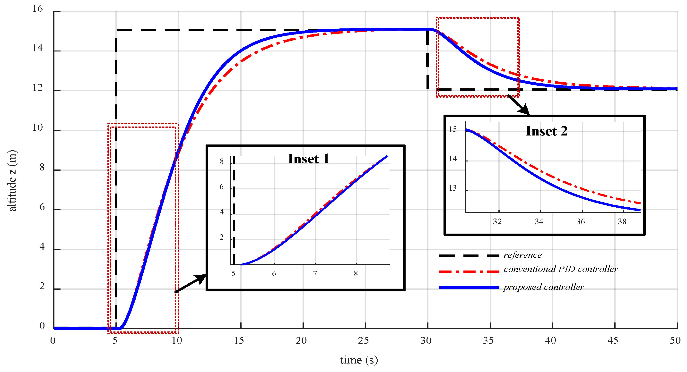
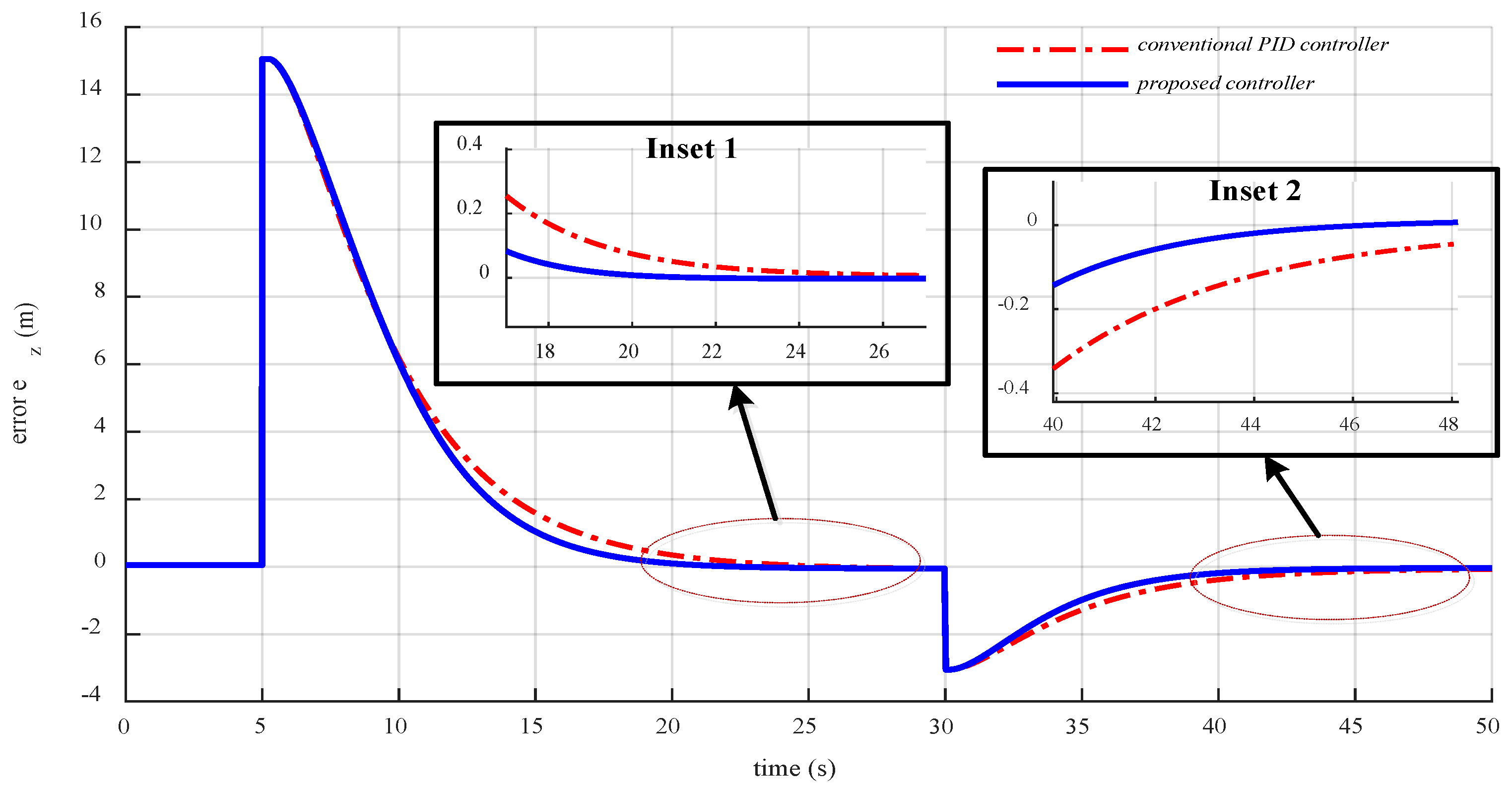
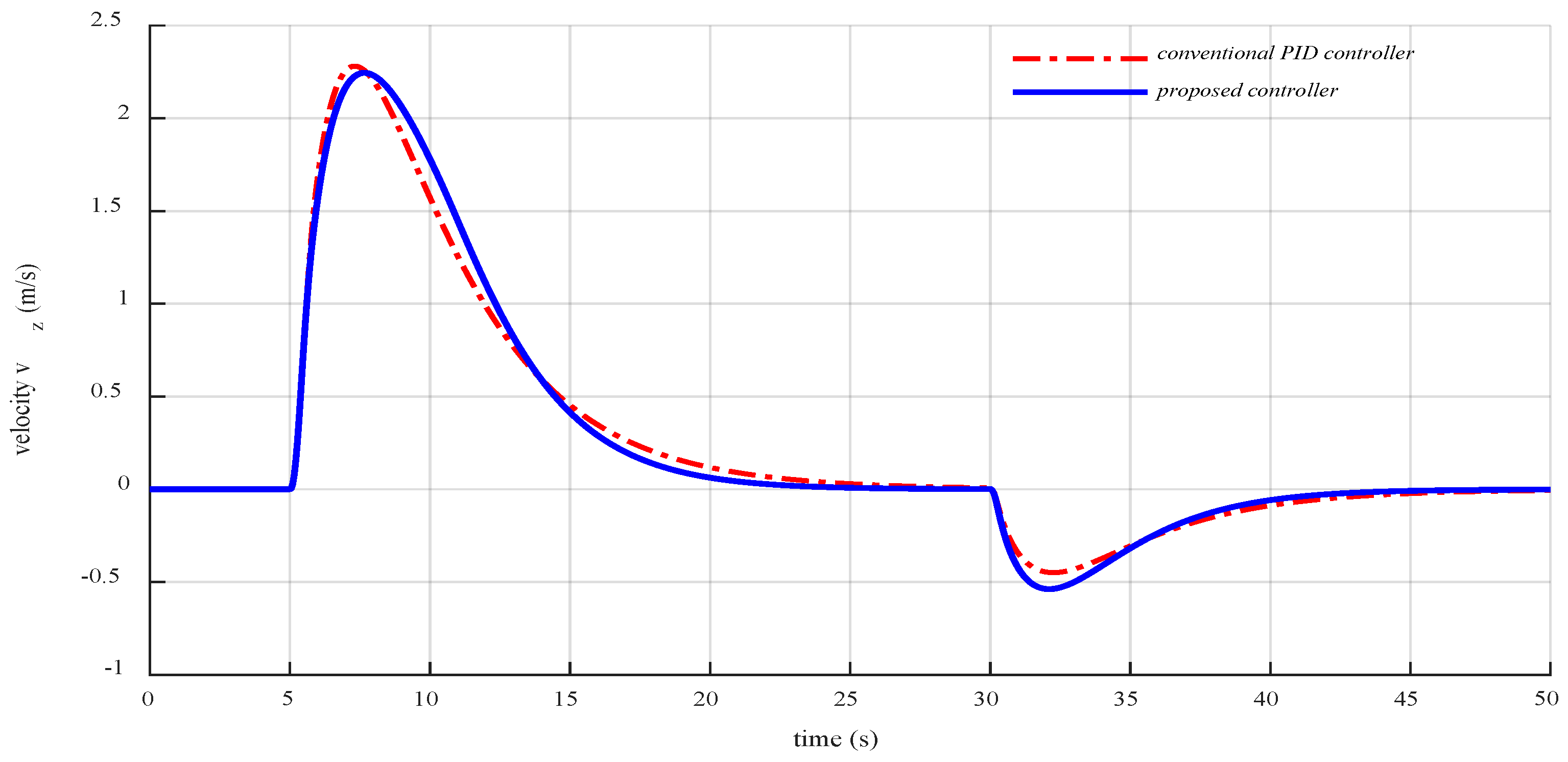
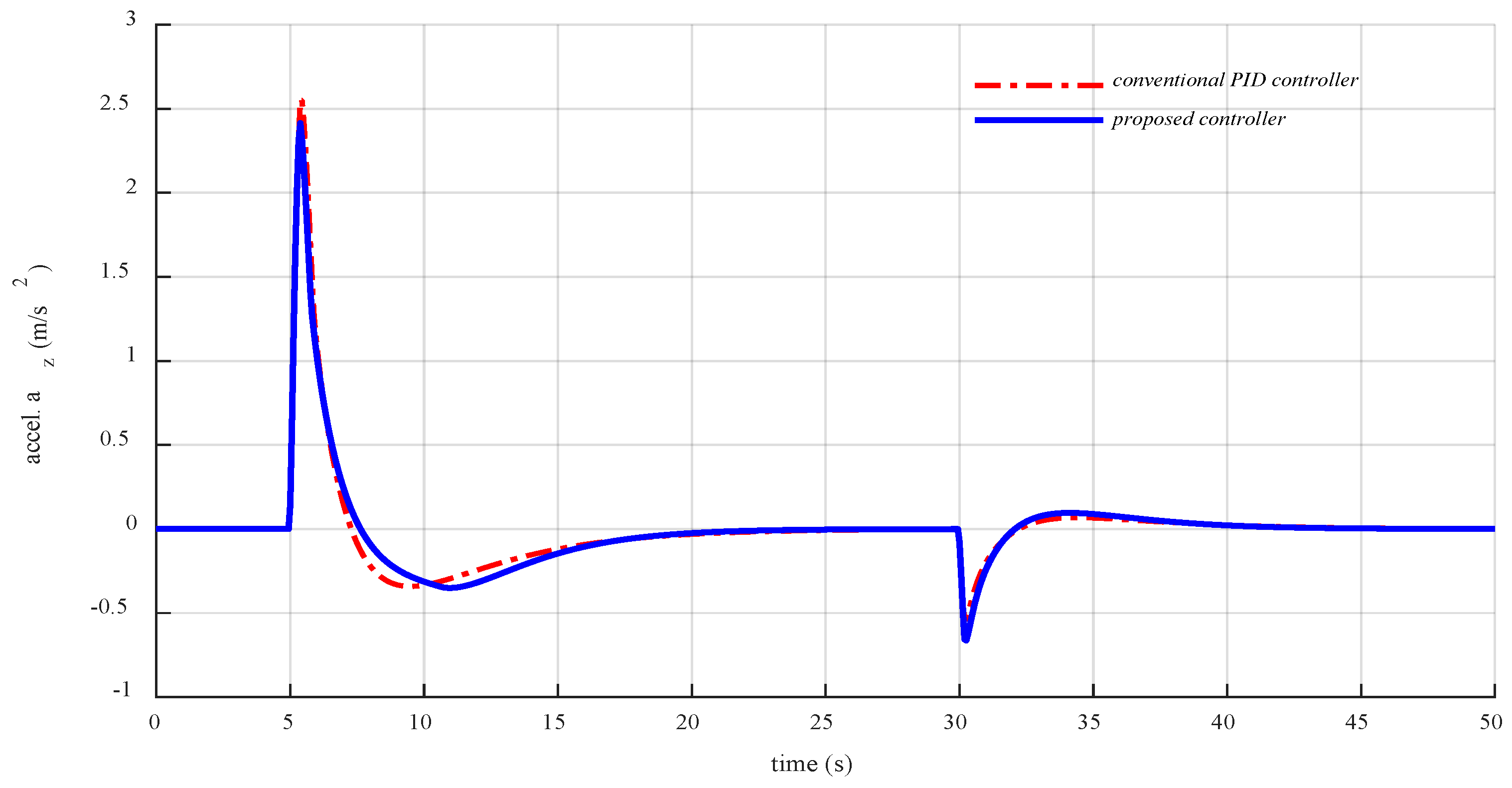
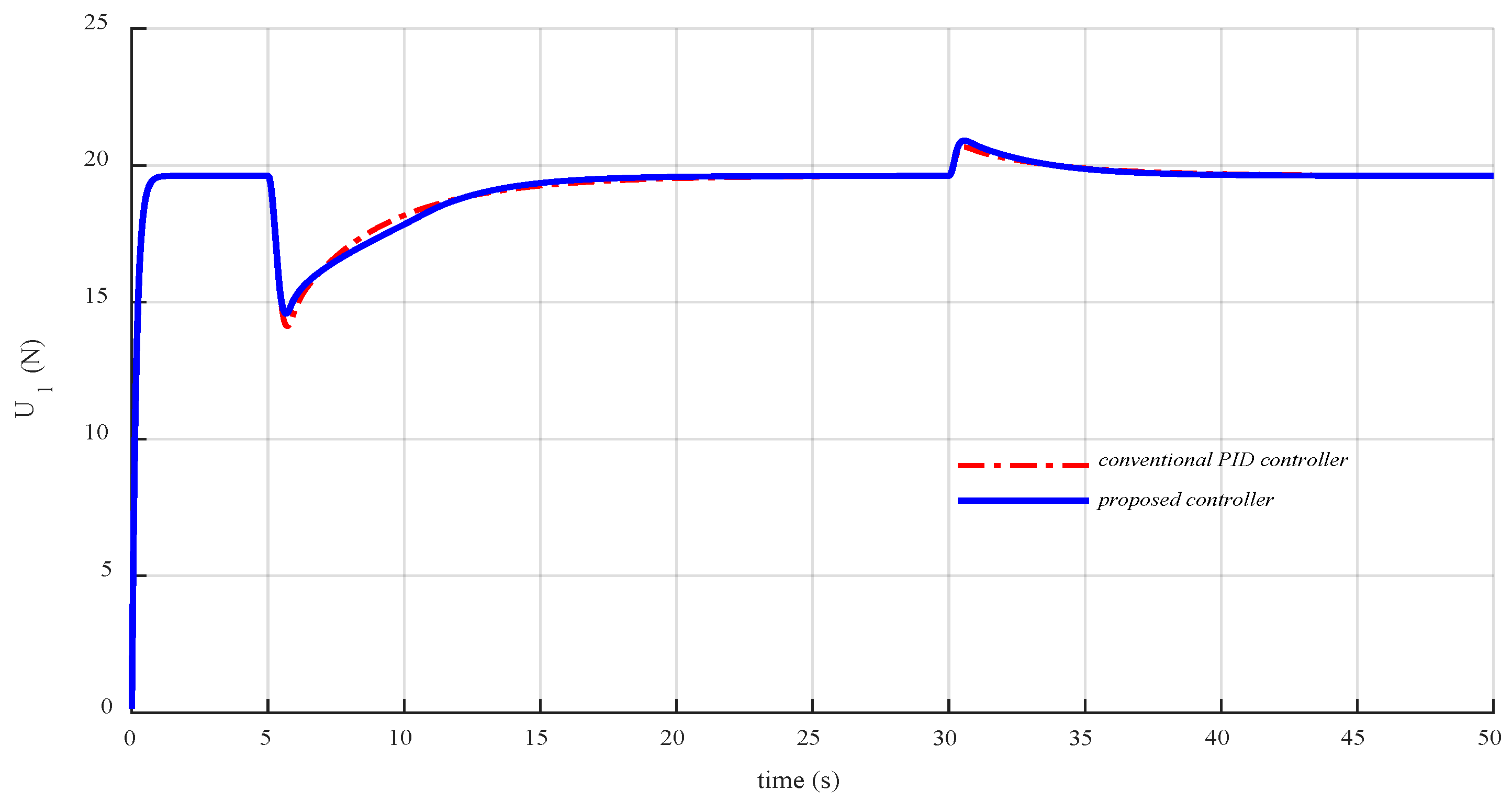
4.2.1. Scenario 1: Tracking Step Altitude References

This scenario consists of three stages: (i) initialization; (ii) take-off; and (iii) descent. During the first five seconds the vehicle is initialized, i.e., it is armed and prepares for take-off. The altitude, vertical velocity, and acceleration are all zero (Figure 7, Figure 8, Figure 9 and Figure 10) and the control signal, U 1 , increases from the initial value of zero to the hovering value of about 19.62 N (Figure 11).
During the second stage (from t = 5 to t = 30 s), the quadcopter takes off and ascends to the desired altitude of 15 m. The altitude responses are nearly identical for both controllers during the early stage of the flight ( 5 t < 9 s in Figure 7). Initially, the conventional PID controller responds slightly faster than our new controller (see Inset 1 in Figure 7). This is reversed during the later stages of the flight when the tracking error becomes smaller than d l ( e z d l 5.1 m) and the controller smoothly switches to the linear mode. For 9 t < 30 s our new controller exhibits a significantly superior performance compared to the conventional PID. With our algorithm, the tracking error converges to a small range closed to zero ( e z is less than 0.5 % ) at t 21 s while the conventional PID only reaches this range around t 25 s (Inset 1 in Figure 8). The velocity, acceleration, and control signal of the conventional PID controller exhibit large amplitudes and slow converging speeds (Figure 9, Figure 10 and Figure 11).
In order to evaluate the performance of our controller when the step amplitude is smaller than d l , during the third stage ( 30 t 50 s), the quadcopter is commanded to descend from the current altitude of 15 m to the desired altitude of 12 m (corresponding to a step of 3 m). If we look at the insets 2 in Figure 7 and Figure 8, it is clearly seen that our controller aggressively responds and quickly reaches the altitude reference at t 45 s while the conventional PID controller only reaches this reference at t 49 s.

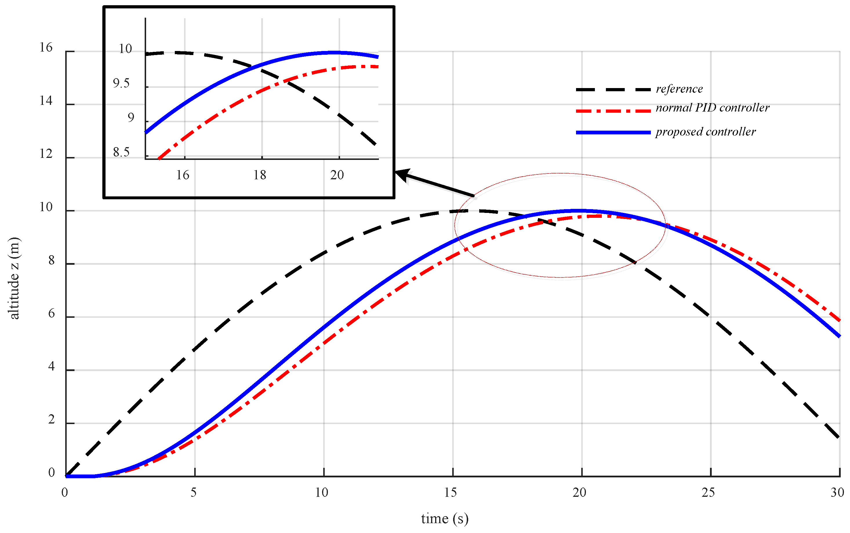
4.2.2. Scenario 2: Tracking a Moving Altitude Reference

Here, the vehicle tracks a moving altitude reference using the same controller gains as in Scenario 1. The moving altitude reference is given as a sine function of time t as:
z d = 10 sin ( 0.1 t )
Clearly, the altitude performance of our new algorithm is superior to a conventional PID controller (Figure 12). While the moving reference altitude reaches 10 m altitude at time t 15.7 s, our controller reaches the peak about 3.8 s later (at t 19.5 s), while the conventional PID controller lags by 9.7 m, reaching the maximum altitude at t 21.1 s. Due to this significant delay, the conventional PID does not even reach the full altitude. In addition, the tracking error of the PID controller exhibits large amplitude oscillation and a slow response compared to our algorithm (Figure 13).

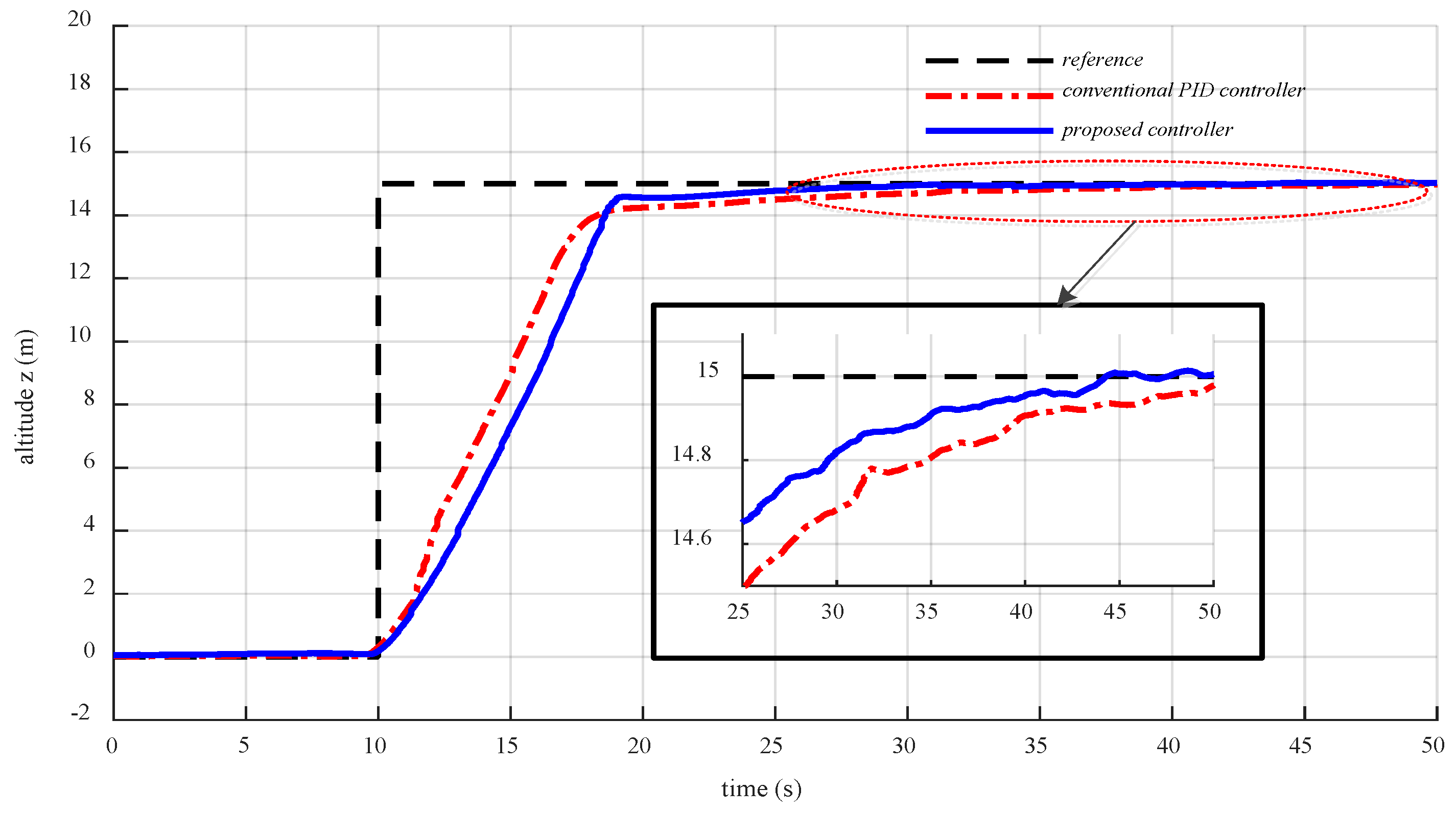
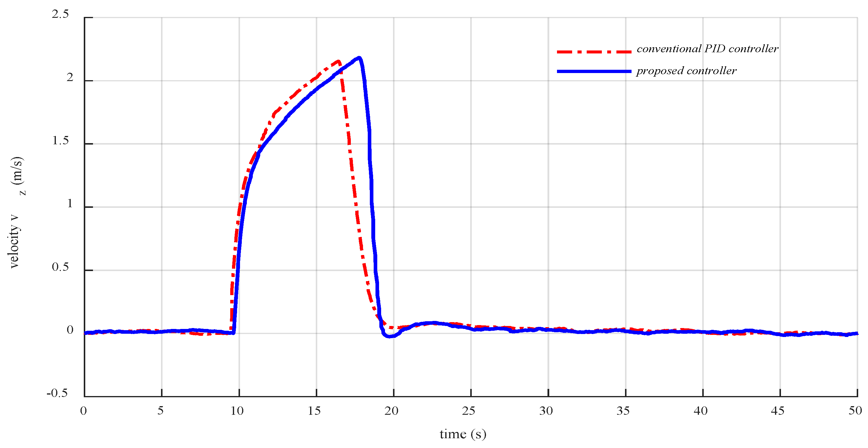
4.3. Experimental Demonstration and Discussions

In this subsection, we present the experimental results of a step-altitude-reference-tracking flight to evaluate the performance and demonstrate the effectiveness of our new controller in real flight conditions. After arming, the quadcopter stays on the ground and prepares for take-off during the first ten seconds (Figure 14). The altitude reference of 15 m is commanded at time t 10 s leading the vehicle to ascend. It is clear that, initially, the conventional PID controller performance is considerably faster than our proposed controller. However, similarly to the simulation results, our new controller exhibits a superior performance compared with the PID controller when the tracking error becomes smaller. If we look at the inset in Figure 14, it is seen that the response of our proposed controller is about 5 s faster than that of the conventional PID controller. The experimental vertical velocity and acceleration performance (Figure 15 and Figure 16) also prove the stability and the effectiveness of the proposed algorithm.
The way our new algorithm exhibits the performance promises a smooth system response when the vehicle starts a movement and a fast target approaching speed when the tracking error becomes small. These properties are useful in performing tasks that require high accuracy and smooth performance such as precision landing, obstacle avoidance, and autonomous delivery to high buildings, etc.

5. Conclusions

This paper presented a new altitude control algorithm for quadcopters. The experimental validation and the numerical simulation results clearly demonstrated that our algorithm performs significantly better compared to a conventional PID controller. While taking advantage of the strength of conventional PID approaches, our method successfully tackles some of their shortcomings. Our algorithm is simple to design and implement, and can be applied to a large range of position control applications for unmanned vehicles. Future work is dedicated to precision landing control design with our proposed controller for an autonomous quadcopter docking and self-charging system.

Author Contributions

Conceptualization, N.X.-M.; methodology, N.X.-M.; software, N.X.-M.; validation, N.X.-M.; formal analysis, N.X.-M.; investigation, N.X.-M.; resources, N.X.-M.; data curation, N.X.-M.; writing—original draft preparation, N.X.-M.; writing—review and editing, N.X.-M. and S.-K.H.; visualization, N.X.-M.; supervision, S.-K.H.; project administration, S.-K.H.; funding acquisition, S.-K.H.

Funding

This research received no external funding.

Acknowledgments

This research was supported by The Competency Development Program for Industry Specialists of the Korean Ministry of Trade, Industry and Energy (MOTIE), operated by Korea Institute for Advancement of Technology (KIAT) (No. N0002431), and The MSIT (Ministry of Science and ICT), Korea, under the ITRC (Information Technology Research Center) support program (IITP-2018-2019-0-01423) supervised by the IITP (Institute for Information & communications Technology Promotion).

Conflicts of Interest

The authors declare no conflict of interest.

References

  1. Xuan-Mung, N.; Hong, S.K. A Multicopter ground testbed for the evaluation of attitude and position controller. Int. J. Eng. Technol. 2018, 7, 65–73. [Google Scholar] [CrossRef]
  2. Yu, Y.; Ding, X. A Quadrotor test bench for six degree of freedom flight. J. Intell. Robot. Syst. 2012, 68, 323–338. [Google Scholar] [CrossRef]
  3. Lee, K.U.; Choi, Y.H.; Park, J.B. Inverse optimal design for position control of a quadrotor. Appl. Sci. 2017, 7, 907. [Google Scholar] [CrossRef]
  4. Nguyen, N.P.; Hong, S.K. Sliding mode thau observer for actuator fault diagnosis of quadcopter UAVs. Appl. Sci. 2018, 8, 1893. [Google Scholar] [CrossRef]
  5. Du, H.; Zhu, W.; Wen, G.; Duan, Z.; Lu, J. Distributed formation control of multiple quadrotor aircraft based on nonsmooth consensus algorithms. IEEE Trans. Cybern. 2017, 49, 342–353. [Google Scholar] [CrossRef]
  6. Borowczyk, A.; Nguyen, D.T.; Nguyen, A.P.V.; Nguyen, D.Q.; Saussié, D.; Ny, J.L. Autonomous landing of a multirotor micro air vehicle on a high velocity ground vehicle. IFAC Pap. Online 2017, 50, 10488–10494. [Google Scholar] [CrossRef]
  7. Ghommam, J.; Saad, M. Autonomous landing of a quadrotor on a moving platform. IEEE Trans. Aerosp. Electr. Syst. 2017, 53, 1504–1509. [Google Scholar] [CrossRef]
  8. Wang, L.; Bai, X. Quadrotor autonomous approaching and landing on a vessel deck. J. Intel. Robot. Syst. 2018, 125–143. [Google Scholar] [CrossRef]
  9. Croon, G.C.H.E.; Ho, H.W.; Wagter, C.; Kampen, E.; Remes, B.; Chu, Q.P. Optic-flow based slope estimation for autonomous landing. Int. J. Micro Air Veh. 2013, 5. [Google Scholar] [CrossRef]
  10. Junaid, A.B.; Konoiko, A.; Zweiri, Y.; Sahinkaya, M.N. Autonomous wireless self-charging for multi-rotor unmanned aerial vehicles. Energies 2017, 10, 803. [Google Scholar] [CrossRef]
  11. Hu, B.; Lu, L.; Mishra, S. Fast, safe and precise landing of a quadrotor on an oscillating platform. In Proceedings of the American Control Conference, Palmer House Hilton, Chicago, IL, USA, 1–3 July 2015. [Google Scholar]
  12. Faust, A.; Palunko, I.; Cruz, P.; Fierro, R.; Tapia, L. Automated aerial suspended cargo delivery through reinforcement learning. Artif. Intell. 2017, 247, 381–398. [Google Scholar] [CrossRef] [Green Version]
  13. Mathew, N.; Smith, S.L.; Waslander, S.L. Planning paths for package delivery in heterogeneous multirobot teams. IEEE Trans. Autom. Sci. Eng. 2015, 12, 1298–1308. [Google Scholar] [CrossRef]
  14. Arbanas, B.; Ivanovic, A.; Car, M.; Haus, T.; Orsag, M.; Petrovic, T.; Bogdan, S. Aerial-ground robotic system for autonomous delivery tasks. In Proceedings of the IEEE International Conference on Robotics and Automation (ICRA), Stockholm, Sweden, 16–21 May 2016. [Google Scholar]
  15. Santos, M.C.P.; Rosales, C.D.; Sarapura, J.A.; Sarcinelli-Filho, M.; Carelli, R. An adaptive dynamic controller for quadrotor to perform trajectory tracking tasks. J. Intell. Robot. Syst. 2019, 93, 5–16. [Google Scholar] [CrossRef]
  16. Jayakrishnan, H.J. Position and attitude control of a quadrotor UAV using super twisting sliding mode. IFAC Pap. Online 2016, 49, 284–289. [Google Scholar] [CrossRef]
  17. Xiong, J.J.; Zheng, E.H. Position and attitude tracking control for a quadrotor UAV. ISA Trans. 2014. [Google Scholar] [CrossRef]
  18. Nadda, S.; Swarup, A. Improved quadrotor altitude control design using second-order sliding mode. J. Aerosp. Eng. 2017, 30, 04017065. [Google Scholar] [CrossRef]
  19. Moawad, N.M.; Elawady, W.M.; Sarhan, A.M. Adaptive PID sliding surface-based second order sliding mode controller for perturbed nonlinear systems. In Proceedings of the 12th International Conference on Computer Engineering and Systems (ICCES), Cairo, Egypt, 19–20 December 2017. [Google Scholar]
  20. González, I.; Salazar, S.; Lozano, R. Chattering-free sliding mode altitude control for a quad-rotor aircraft: Real-time application. J. Intell. Robot. Syst. 2014, 73, 137–155. [Google Scholar] [CrossRef]
  21. Muliadi, J.; Kusumoputro, B. Neural network control system of UAV altitude dynamics and its comparison with the PID control system. J. Adv. Trans. 2018, 1–18. [Google Scholar] [CrossRef]
  22. Mustapa, Z.; Saat, S.; Husin, S.H.; Abas, N. Altitude controller design for multi-copter UAV. In Proceedings of the IEEE International Conference on Computer, Communication, and Control Technology (I4CT 2014), Langkawi, Malaysia, 2–4 September 2014. [Google Scholar]
  23. Santos, M.F.; Pereira, V.S.; Ribeiro, A.C.; Silva, M.F.; Vidal, M.J.D.C.V.F.; Honorio, L.M.; Cerqueira, A.S.; Oliveira, E.J. Simulation and comparison between a linear and nonlinear technique applied to altitude control in quadcopters. In Proceedings of the 18th International Carpathian Control Conference (ICCC), Sinaia, Romania, 28–31 May 2017; pp. 234–239. [Google Scholar]
  24. Pounds, P.E.I.; Bersak, D.R.; Dollar, A.M. Stability of small-scale UAV helicopters and quadrotors with added payload mass under PID control. Auton. Robots 2012, 33, 129–142. [Google Scholar] [CrossRef]
  25. Salih, A.L.; Moghavvemi, M.; Mohamed, H.A.F.; Gaeid, K.F. Modelling and PID controller design for a quadrotor unmanned air vehicle. In Proceedings of the IEEE International Conference on Automation, Quality and Testing, Robotics (AQTR), Cluj-Napoca, Romania, 28–30 May 2010. [Google Scholar]
  26. Li, J.; Li, Y. Dynamic analysis and PID control for a quadrotor. In Proceedings of the IEEE International Conference on Mechatronics and Automation, Beijing, China, 7–10 August 2011. [Google Scholar]
  27. Ahmed, A.H.; Ouda, A.N.; Kamel, A.M.; Elhalwagy, Y.Z. Attitude stabilization and altitude control of quadrotor. In Proceedings of the 12th International Computer Engineering Conference (ICENCO), Cairo, Egypt, 28–29 December 2016. [Google Scholar]
  28. Khan, H.S.; Kadri, M.B. Attitude and altitude control of quadrotor by discrete PID control and non-linear model Predictive control. In Proceedings of the International Conference on Information and Communication Technologies (ICICT), Karachi, Pakistan, 12–13 December 2015. [Google Scholar]
  29. Bolandi, H.; Rezaei, M.; Mohsenipour, R.; Nemati, H.; Smailzadeh, S.M. Attitude control of a quadrotor with optimized PID controller. Intell. Control Autom. 2013, 4, 335–342. [Google Scholar] [CrossRef]
  30. Thanh, H.L.N.N.; Hong, S.K. Quadcopter robust adaptive second order sliding mode control based on PID sliding surface. IEEE Access 2018, 6, 66850–66860. [Google Scholar] [CrossRef]
  31. Thanh, H.L.N.N.; Nguyen, N.P.; Hong, S.K. Simple nonlinear control of quadcopter for collision avoidance based on geometric approach in static environment. Int. J. Adv. Robot. Syst. 2018. [Google Scholar] [CrossRef]
  32. Nguyen, N.P.; Hong, S.K. Fault-tolerant control of quadcopter UAVs using robust adaptive sliding mode approach. Energies 2019, 12, 95. [Google Scholar] [CrossRef]
  33. Nguyen, N.P.; Hong, S.K. Position control of a hummingbird quadcopter augmented by gain scheduling. Int. J. Eng. Res. Technol. 2018, 11, 1485–1498. [Google Scholar]
  34. Milhim, A.B.; Zhang, Y. Gain Scheduling based PID controller for fault tolerant control of a quad-rotor UAV. In Proceedings of the AIAA Infotech@Aerospace, Atlanta, GA, USA, 20–22 April 2010. [Google Scholar]
  35. Gautam, D.; Ha, C. Control of a quadrotor using a smart self-tuning fuzzy PID controller. Int. J. Adv. Robot. Syst. 2013, 10. [Google Scholar] [CrossRef]
  36. Goodarzi, F.; Lee, D.; Lee, T. Geometric nonlinear PID control of a quadrotor UAV on SE(3). In Proceedings of the European Control Conference (ECC), Zürich, Switzerland, 17–19 July 2013. [Google Scholar]
  37. Takagi, T.; Sugeno, M. Fuzzy identification of systems and its applications to modeling and control. IEEE Trans. Syst. Man Cybern. 1985, 1, 116–132. [Google Scholar] [CrossRef]
  38. Liu, H.; Shi, P.; Chadli, M. Finite-time stability and stabilisation for a class of nonlinear systems with time-varying delay. Int. J. Syst. Sci. 2016, 47, 1433–1444. [Google Scholar] [CrossRef]
  39. Estrada, F.R.L.; Ponsart, J.C.; Theilliol, D.; Zhang, Y. LPV Model-based tracking control and robust sensor fault diagnosis for a quadrotor UAV. J. Intel. Robot. Syst. 2016, 84, 163–177. [Google Scholar] [CrossRef]
  40. Rangajeeva, S.L.M.D.; Whidborne, J.F. Linear parameter varying control of a quadrotor. In Proceedings of the 6th International Conference on Industrial and Information Systems, Peradeniya, Sri Lanka, 16–19 August 2011. [Google Scholar]
  41. Stojcsics, D.; Molnár, A. Autonomous takeoff and landing control for small size unmanned aerial vehicles. Comp. Inform. 2013, 32, 1117–1130. [Google Scholar]
  42. Feng, Y.; Zhang, C.; Baek, S.; Rawashdeh, S.; Mohammadi, A. Autonomous landing of a UAV on a moving platform using model predictive control. Drones 2018, 2, 34. [Google Scholar] [CrossRef]
  43. Zhou, Z.; Wang, H.; Hu, Z. Event-based time varuing formation control for multiple quadrotor UAVs with markovian switching topologies. Complexity 2018. [Google Scholar] [CrossRef]
  44. Qi, Y.; Zhou, S.; Kang, Y.; Yan, S. Formation control for unmanned aerial vehicles with directed and switching topologies. Int. J. Aerosp. Eng. 2016. [Google Scholar] [CrossRef]
  45. Zhang, X.; Li, X.; Wang, K.; Lu, Y. A survey of modelling and identification of quadrotor robot. Abstr. Appl. Anal. 2014, 320526. [Google Scholar] [CrossRef]
  46. Wang, H.; Ye, X.; Tian, Y.; Zheng, G.; Christov, N. Model-free–based terminal SMC of quadrotor attitude and position. IEEE Trans. Aerosp. Electron. Syst. 2016, 52, 2519–2528. [Google Scholar] [CrossRef]
  47. Zhang, D.; Qi, H.; Wu, X.; Xie, Y.; Xu, J. The quadrotor dynamic modeling and indoor target tracking control method. Math. Probl. Eng. 2014. [Google Scholar] [CrossRef]
  48. Alexis, K.; Nikolakopoulos, G.; Tzes, A. Model predictive quadrotor control: Attitude, altitude and position experimental studies. IET Control. Theory Appl. 2012, 6, 1812–1827. [Google Scholar] [CrossRef]
  49. Guruganesh, R.; Bandyopadhyay, B.; Arya, H.; Singh, G.K. Design and hardware implementation of autopilot control laws for MAV using super twisting control. J. Intell. Robot. Syst. 2017, 90, 455–471. [Google Scholar] [CrossRef]
Figure 1. Quadcopter configuration.
Applsci 09 02122 g001
Figure 2. Full quadcopter controller scheme. The proposed algorithm is applied to the altitude control while conventional proportional–integral–derivative (PID) controllers are used for horizontal position and attitude control.
Applsci 09 02122 g002
Figure 3. The multi-loop altitude control scheme of the quadcopter. The proposed algorithm is implemented in the outer-loop while a PID controller is used in the inner-loop.
Applsci 09 02122 g003
Figure 4. Graphical illustration of the curve ( S ) (blue), the line ( Δ ) (green), and their relations.
Applsci 09 02122 g004
Figure 5. Quadcopter platform used for the experimental demonstration.
Applsci 09 02122 g005
Figure 6. The system signal flow block diagram.
Applsci 09 02122 g006
Figure 7. Comparison of altitude performance between our new controller and a conventional PID controller for Scenario 1 (tracking a step altitude reference).
Applsci 09 02122 g007
Figure 8. Comparison of altitude tracking error convergence between our new controller and a conventional PID controller for Scenario 1.
Applsci 09 02122 g008
Figure 9. Comparison of the vertical velocity performance between our new controller and a conventional PID controller for Scenario 1.
Applsci 09 02122 g009
Figure 10. Comparison of the vertical acceleration performance between our new controller and a conventional PID controller for Scenario 1.
Applsci 09 02122 g010
Figure 11. Comparison of the control signal, U 1 , between our new controller and a conventional PID controller for Scenario 1.
Applsci 09 02122 g011
Figure 12. Comparison of altitude performances between our new controller and a conventional PID controller for Scenario 2 (tracking a moving altitude reference).
Applsci 09 02122 g012
Figure 13. Comparison of the altitude tracking error convergence between our new controller and a conventional PID controller in Scenario 2.
Applsci 09 02122 g013
Figure 14. Comparison of experimental altitude performance between our new controller and a conventional PID controller.
Applsci 09 02122 g014
Figure 15. Comparison of the experimental vertical velocity performance between our new controller and a conventional PID controller.
Applsci 09 02122 g015
Figure 16. Comparison of the experimental vertical acceleration performance between our new controller and a conventional PID controller.
Applsci 09 02122 g016
Table 1. System parameters used for the simulations.
ParameterValueUnit
m2.0kg
J x 0.0121kg.m2
J y 0.0119kg.m2
J z 0.0223kg.m2
l0.23m
g9.81m/s2
C t 7.732 (10−6)Ns2
C b 1.275 (10−7)Nms2
Table 2. Controller parameters and the altitude references.
ParametersValue and Unit
a max 2.5 m/s2
k0.7
k p 1.1
k i 0.002
k d 0.2
z d 0, 15, 12, and 10 sin (0.1t) m

