1. Introduction
Strengthening of historical masonry walls is critical for heritage reservation, because these walls are the major load-bearing members in many architectural heritages around the world. The topic has attracted intensive research [
1,
2,
3,
4,
5]. Masonry walls can be strengthened by applying externally bonded layers or strips. The former covers the walls’ surface entirely while the latter covers partially. Given appropriate strengthening designs, they would not intervene the target buildings significantly and would not influence the buildings’ aesthetics. Therefore, they are also applicable for strengthening the historical buildings. The two methods can significantly reduce the working stress in regular masonry walls under different load cases, and then comprehensively rehabilitate the walls’ performances [
6,
7,
8]. However, special considerations deserve when they are used for the historical brick masonry walls [
9].
First, it is difficult for the strengthening layers or strips to deform well with the masonry substrates, especially under high in-plane compression. Because the elastic modulus of the historical masonry substrate is extraordinary lower than that of the strengthening layers or strips. Under the circumstance, the layers or strips do not activate much of their strength, and then the resistance of the strengthened walls can still be low [
10]. In addition, the stiffness of the strengthened walls can also be low, resulting in risks of unacceptable lateral deformation or even collapse during earthquakes. Although the issues can be relieved by prestressing the strengthening strips, it requires a large anchor length of the strips on the weak historical masonry substrates. Anchorage relaxation caused by large deformation and creep of the soft historical masonry can reverse the effect of prestressing [
11,
12].
Second, surface preparation is restricted, or even prohibited, when strengthening the historical masonry walls. Because the historical masonry substrate is vulnerable and sensitive. Under the circumstance, the bondage of the strengthening layers or strips is difficult to guarantee. In addition, unfavorable stress concentrations can take place within masonry substrates, the externally bonded layers or strips, and their interfaces. If the strengthening layers or strips are made of FRP with anisotropic and brittle nature, the stress concentration can result in piercing or threading effects on them [
13].
Third, it is difficult to achieve favorable integrity of the strengthened historical masonry walls, if the walls have been damaged significantly before strengthening. When applying strengthening layers on these walls, the integrity of the damaged substrates and the layers are unreliable because it is subject to many uncertain factors. For example, the walls’ aspect ratio, the damage distribution and extent, the properties of the bricks and mortar, the properties of the strengthening materials, and so on [
14,
15,
16,
17]. When applying strengthening strips on these walls, the integrity of the strengthened walls may relate to the strip configuration [
18]. For example, damaged parts of the walls that are not covered by the strengthening strips can undergo large deformation under high stress, and result in collapse of the walls potentially [
14].
Besides, an important requirement for strengthening historical masonry walls is the reversibility of the intervention [
19,
20,
21], which keeps the possibility to remove and replace the retrofit when the advances in technology will allow better strategies.
Considering the characteristics of the historical masonry walls, to cover their surfaces entirely using strengthening layers is preferable. The materials used to construct the strengthening layers should deform well with the soft masonry substrates, have favorable strength, and have good ductility. The ultra-high performance concrete (UHPC) is a potential candidate because of its favorable features [
22]. First, the ductility of the UHPC is much better than that of the historical masonry, and the favorable ductility helps to bring in good energy dissipation ability of the strengthened walls. Second, the tensile strength, the compressive strength, and the shear strength of the UHPC are much higher than those of the historical masonry respectively, and the higher strength ensures the strengthening effect under different stress states. Third, the UHPC has no coarse aggregate and then has good grouting ability. This feature has been verified by its successful applications in grouting the rebar-splicing couplers in prefabricated concrete members [
23]. With the good grouting ability, the UHPC can flow into and fill the existing damages in the masonry substrates before hardening. Such a mechanism makes the UHPC deform well with the masonry substrates, and it relieves influence of the seasonal difference between the thermal strain of the UHPC layers and the masonry substrates.
Although the UHPC layers are not completely removable after being applied, their thickness can be very small because they do not require reinforcement inside. When the advances in technology allow better strategies, they can be applied on top of the thin UHPC layers without changing the profile of the masonry walls. From this angle, the UHPC layers allow the realization of better strategies like those reversible retrofitting strategies do.
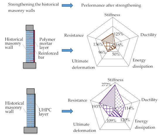
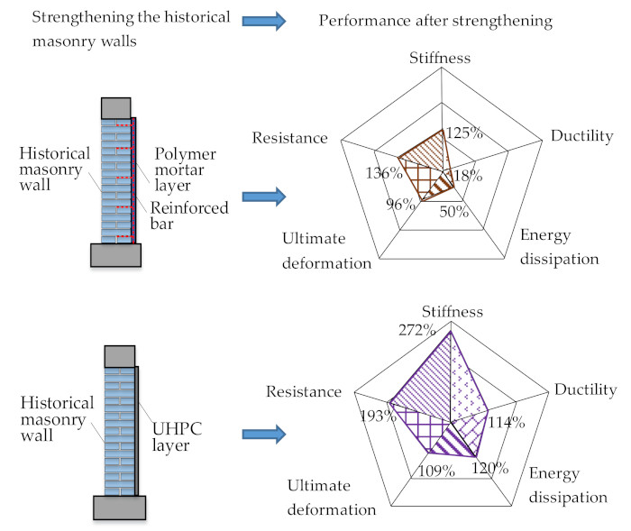
The research about the strengthening effect of applying UHPC layers on historical masonry walls is not enough yet. To contribute to the field, the authors conduct pseudo-static experiments on historical squat masonry walls strengthened by UPPC layers and reinforced polymer mortar layer, and they compare the strengthening effect of the two kinds of layers. The structure of the paper is as follows. In
Section 2, the authors present a detailed experimental scheme with special considerations on characteristics of the historical brick masonry walls. In
Section 3, they present and compare the experimental results in terms of failure mode, in-plane shear resistance, stiffness degradation, and ductility of the walls. These results reflect the static and seismic performance of the walls quantitatively. In
Section 4, the authors evaluate the strengthening effect of applying the UHPC layers, with emphasis on the favorable interaction between the UHPC and the masonry substrates. Finally, they summarize the research findings in
Section 5.
2. Experimental Scheme
2.1. Preparation of the Historical Masonry
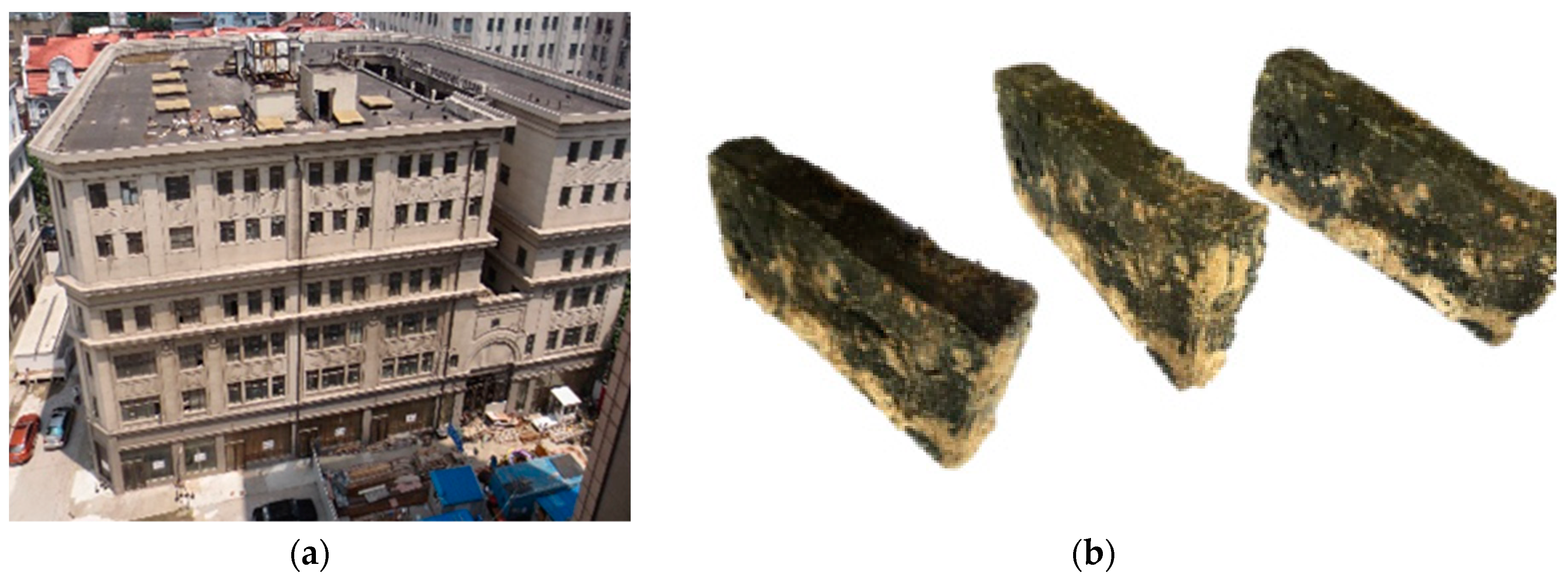
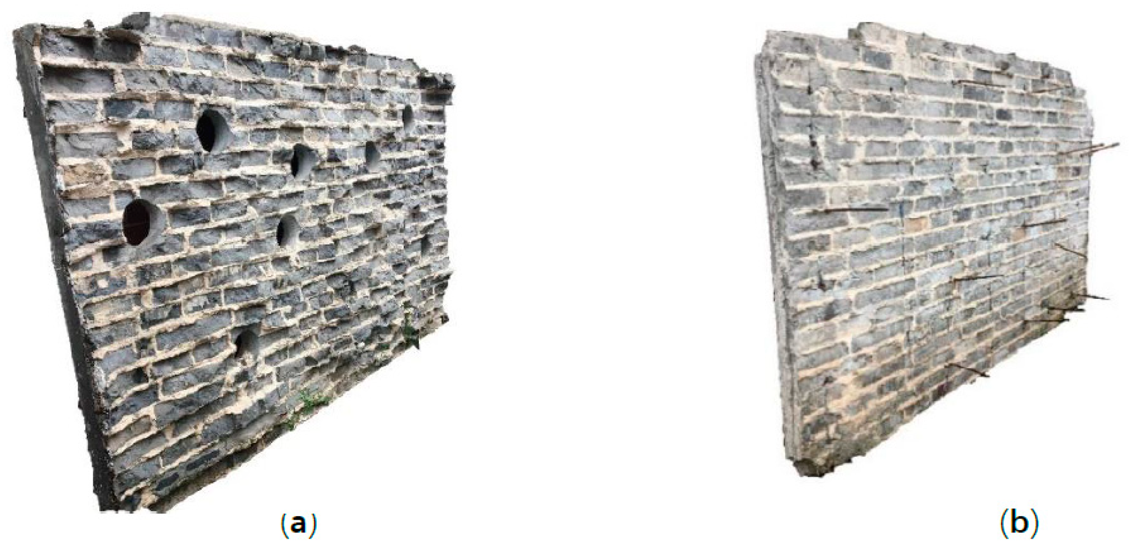
The above-mentioned characteristics of historical brick masonry walls influence the effect of the strengthening methods significantly. To simulate the historical brick masonry walls under strengthening authentically, the bricks used in this research were collected from a real historical building under rehabilitation, as shown in
Figure 1a. The six-story building was constructed in 1929 and it has a mixed structure that consisted of concrete frames, masonry walls, and concrete floors. The height of story 1 to story 6 are 4. 877 m, 3.353 m, 3.353 m, 3.353 m, 3.000 m, and 3.000 m, respectively. The plan of each story is close to a rectangular whose dimension is 17.2 m × 32.7 m. The bricks used in this research were collected from the masonry walls in story 5. The historical bricks had damages and their shape was irregular, as shown in
Figure 1b. They helped to reproduce the rough brick-mortar interface within the historical walls. The authors measured the strength of the historical bricks by conducting compressive tests of 10 random samples. It found that the average compressive strength was 6.2 N/mm
2 and the standard deviation was 0.5 N/mm
2.
The mortar used to construct the bed and head joints had a special mixture that ensured the low strength. The mixture contained no Portland cement, but it contained meshed powder of mortar beds collected from the same historical building. Such a mixture simulated the ingredients of the historical mortar, and then helped to reproduce the bonding between bricks and mortar in the historical walls. The weight ratio of water, lime, and sand in the mortar was 1:1:6. The authors measured the strength of the mortar by conducting compressive tests on six cubic mortar specimens. The specimens were sampled from the batch that would be used to construct the walls. It found that the average compressive strength was 0.4 N/mm2 and the standard deviation was 0.13 N/mm2.
Three masonry prisms whose size were 240 mm × 365 mm × 766 mm were constructed and cured simultaneously with the walls. The authors measured the masonry strength by conducting compressive tests on the prisms. It found that the average compressive strength was 0.74 N/mm2 and the standard deviation was 0.11 N/mm2.
2.2. Mechanical Properties of the Strengthening Materials
Two kinds of layer were used to strengthen the walls, i.e., the UHPC layer and the reinforced polymer mortar layer. The latter was constructed by coating a grid of steel bars with polymer mortar. The UHPC was mixed by water, cement, superfine cement, sand, scoria, high-performance water reducer, and fine steel fiber with a weight ratio of 1:2.32:1.14:5.30:2.34:0.11:0.59. The polymer mortar was mixed by water, cement, sand, and additive with a weight ratio of 1: 3.33: 6.67: 0.6. The reinforced steel bars were of class HPB235 in the Chinese code GB 50010-2010 and their sectional diameter was 6 mm. Mechanical properties of the strengthening materials are shown in
Table 1.
The elastic modulus and the thermal expansion coefficient of the UHPC are far different from that of masonry. Therefore, the seasonal variation of thermic strain of the UHPC will be different from that of the masonry substrate. The strain difference would provoke unfavorable stress in the masonry, but the interaction between the UHPC and the masonry substrates would relieve the stress, as explained in
Section 4.2.
2.3. Construction of the Squat Masonry Walls
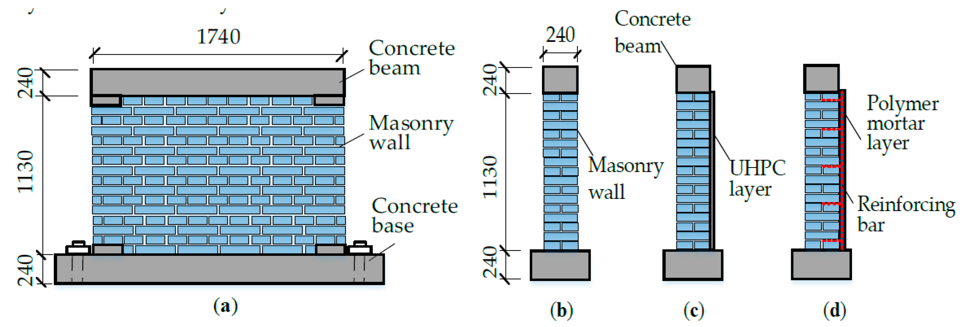
Three squat walls were constructed using the above-mentioned materials and labeled by W1, W2, and W3 respectively. The W1 was constructed without any strengthening measure, the W2 was constructed and strengthened by a UHPC layer, and the W3 was constructed and strengthened by a reinforced polymer mortar layer. The authors applied in-plane lateral load cyclically on W1 under constant vertical compression until the wall failed, and then strengthened the failed W1 in-situ with a UHPC layer. The strengthened wall was labeled as W1S, and it was loaded to failure again.
To limit the variety of structural details, two senior technicians constructed the masonry walls in three consecutive days and then cured the bare walls for two weeks. After curing the walls, the strengthening was finished in three consecutive days. On day 1, the mixing of the UHPC and strengthening with the UHPC layer was completed. On day 2, the grid of steel bars was formed. On day 3, strengthening with the reinforced polymer mortar layer was completed. After the strengthening and before the tests, the authors cured the strengthened walls for 28 days in a stable lab environment. The curing temperature was between 17 °C and 23 °C, and the environmental humidity was greater than 90%.
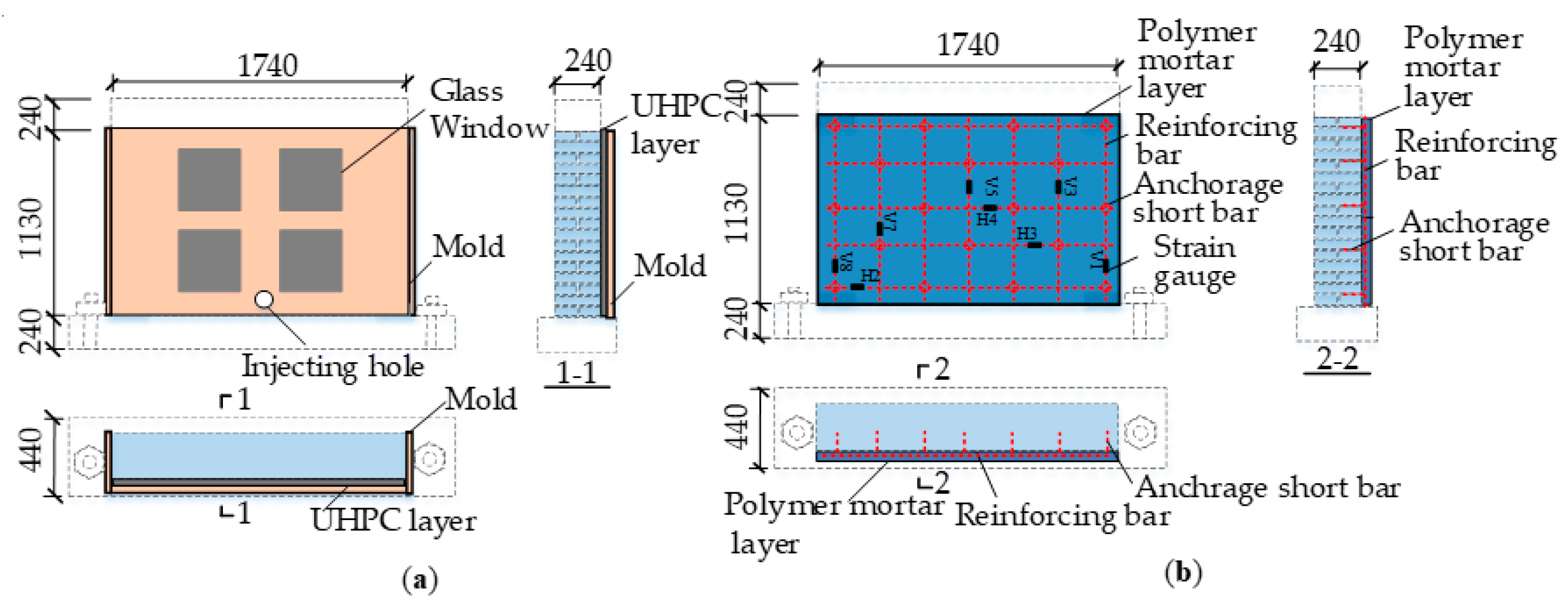
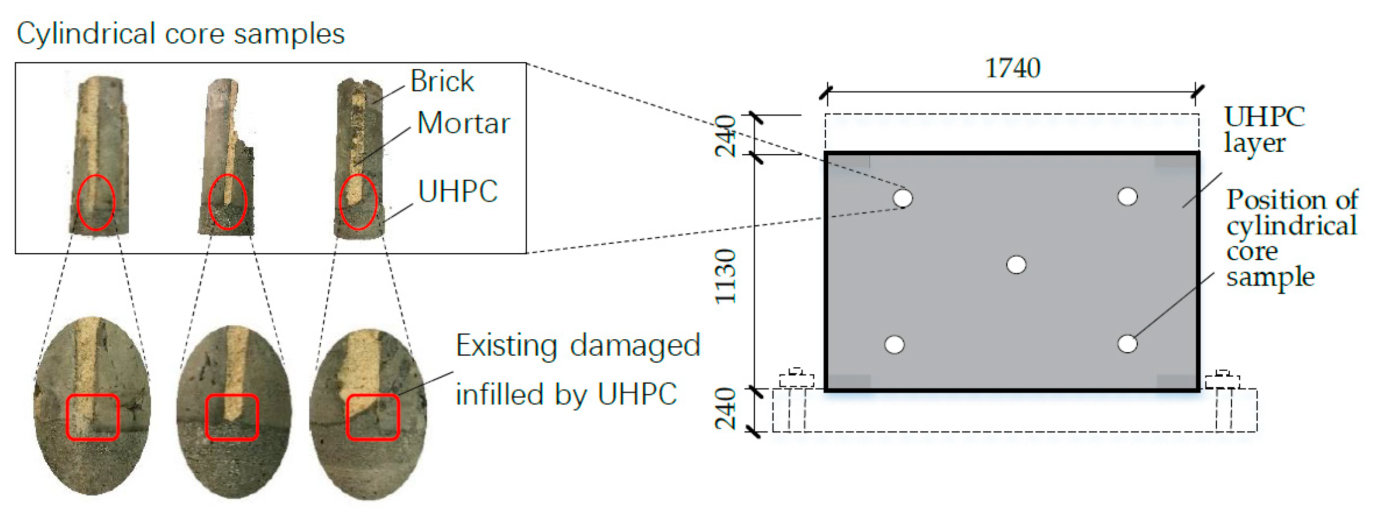
The profile of the walls is shown in
Figure 2. Thickness of the walls was 240 mm and thickness of the mortar joints was 10 mm, like those measured in the historical building. Thickness of the UHPC layers on W2 and W1S was 40 mm, like that of the general strengthening layers used in practices (in China). The UHPC layers are thinner than other strengthening layers that work with inner reinforcement. Therefore, it is possible to apply extra strengthening measures on top of the UHPC layers without changing the profile of the historical walls. The authors controlled the thickness of the UHPC layers using a wooden mold, as shown in
Figure 3a. They injected the UHPC batch from a hole on the bottom of the mold, until the space between the mold and the wall surfaces was filled. During the procedure, the UHPC batch also immersed and filled the existing damages in the walls. Such a strengthening procedure had slight intervention on the damaged masonry walls, as required by most rehabilitation practices. Moreover, it potentially helped to improve the integrity of the masonry substrates, the elastic modulus of the target walls, and the bondage between the UHPC layers and the masonry substrates.
Comparatively, strengthening with the reinforced polymer mortar layer was more complicated. First, the surface of the masonry substrate was cleared, and then anchoring short reinforcing bars were planted into the masonry, as shown in
Figure 3b. As the following step, the reinforced grid was hung on the anchoring short bars and then was fasten by binding. The polymer mortar was then spread onto the cleared surface of the masonry substrate by two times. After the first time, the polymer mortar layer was just thick enough to cover the reinforced grid; after the second time, the polymer mortar layer reached its design thickness of 50 mm. Planting of anchoring short bars and spreading of polymer mortar had obvious intervention on the target wall. These measurements can be inapplicable if the masonry substrate had been damaged severely, as the case of W1S. In addition, the polymer mortar layer had a minimum thickness to coat the reinforced grid effectively. Such a minimum thickness is not always applicable for rehabilitation of historical buildings.
It should be noted that the aspect ratio has significant influence on the performance of masonry walls. However, the amount of the collected historical bricks and mortar was limited and not enough to construct more specimens with different aspect ratios. Therefore, the authors focused on the squat walls that is a typical class of members in historical structures. The in-plane shear failure of the squat walls is brittle and the strengthening effect of the squat walls could be more convincing.
By comparing the experimental results of W1, W2, and W1S, strengthening effect of the UHPC layer for masonry walls with different damage extent can be evaluated. By comparing the experimental results of W1 and W3, strengthening effect of the reinforced polymer mortar layer can be evaluated. By comparing the experimental results of W1, W2, and W3, the difference in the strengthening effect of the UHPC layer and the reinforced polymer mortar layer can be evaluated.
2.4. Test Setup and Loading Mechanism
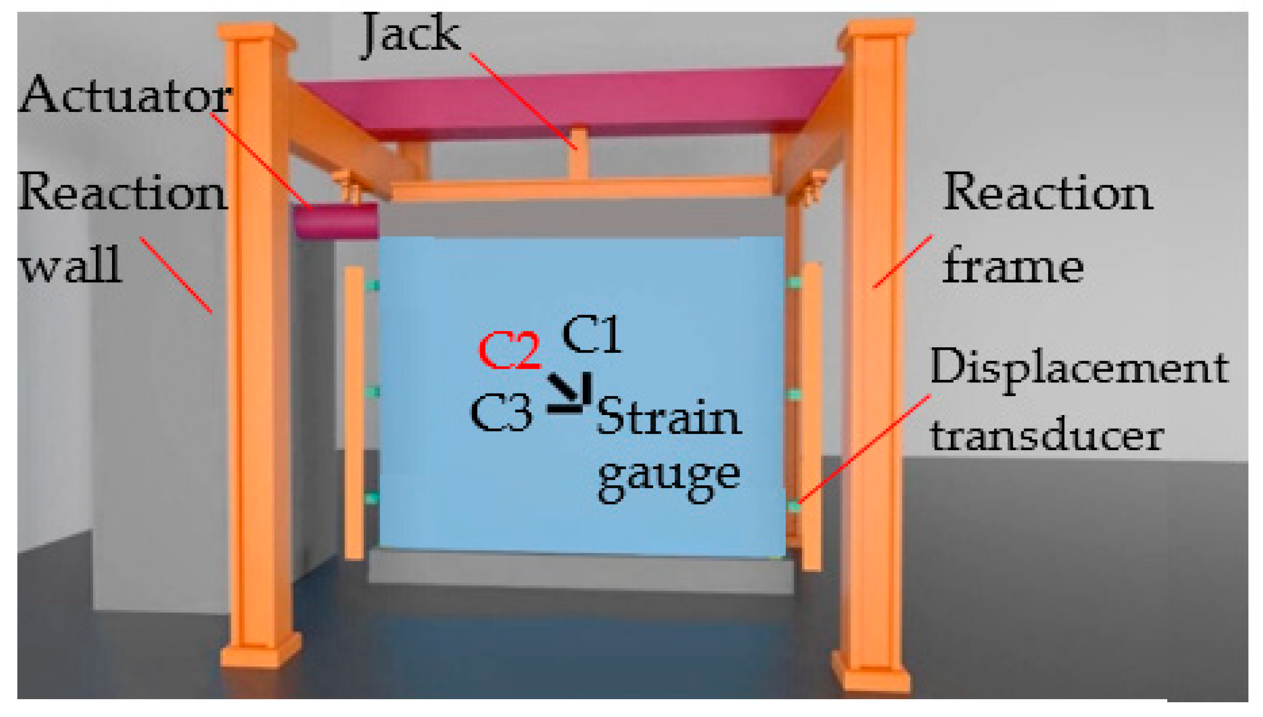
The test setup and transducer layout are shown in
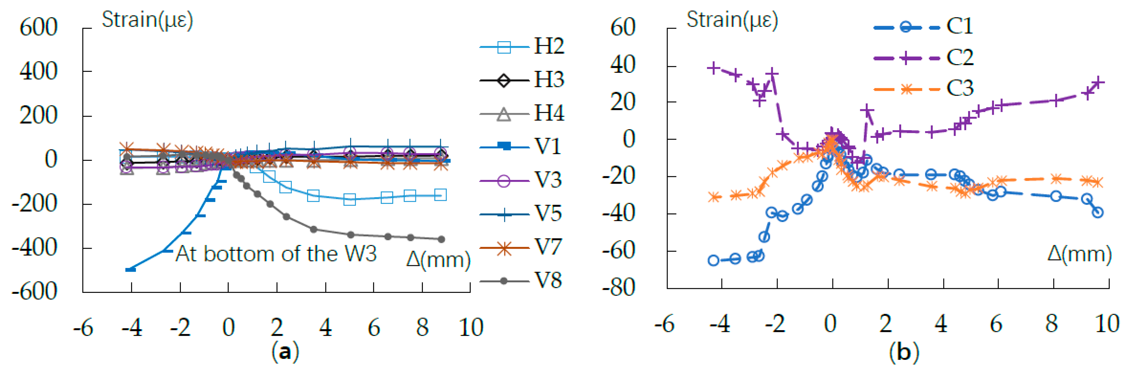
Figure 4. The displacement transducers were used to measure deformation of the walls, and their records were used to evaluate the walls’ failure modes. The strain gauges C1, C2, and C3 on the strengthening layers, along with those on the reinforcing bars and shown in
Figure 3b, were used to evaluate the strain distribution within the walls and to evaluate the deformation of the strengthening layers.
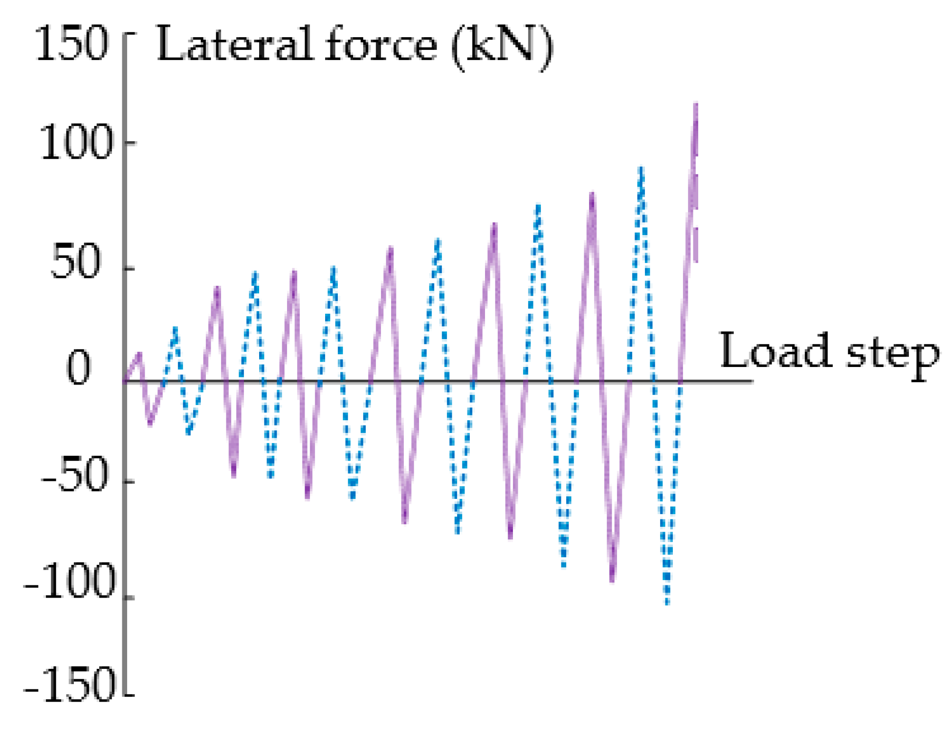
The loading mechanism was same for all the walls. Vertical compression was firstly applied by a jack and then remained unchanged, resulting in a constant compressive ratio of 0.3 on the wall being tested. The compressive ratio is typical of the bottom walls of regular two-story masonry buildings (in China). After vertical loading, cyclical lateral forces were applied along the top concrete beam by a servo-hydraulic actuator. The lateral loading stopped if the force of the actuator dropped by 15% or more, as illustrated in
Figure 5.
3. Experimental Results
3.1. Deformation and Failure Mode
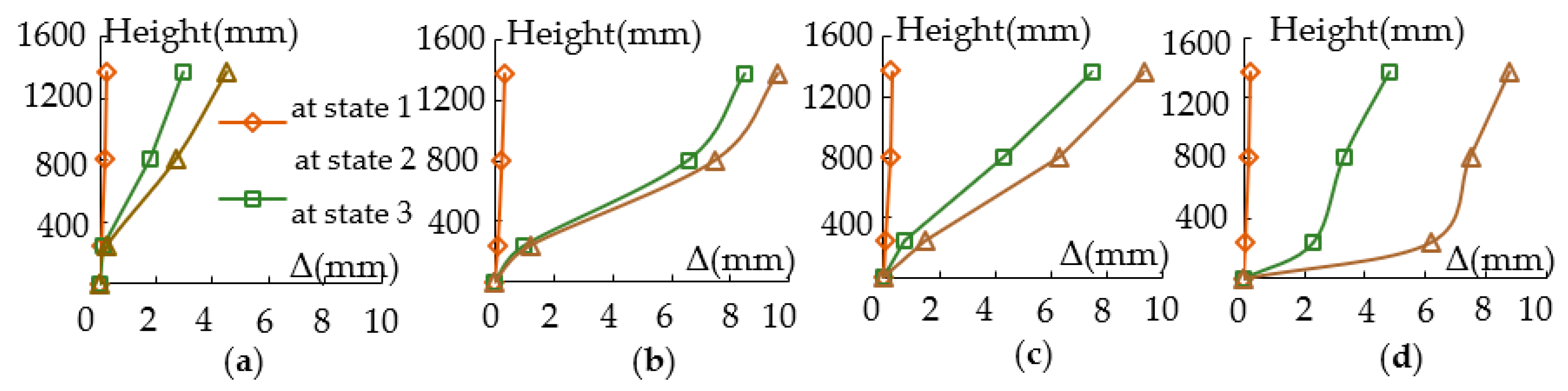
There were three typical states of the walls during they deformed under the lateral loading. At state 1, major cracks in the walls became visible; at state 2, lateral forces on the walls reached their peak values; and at state 3, the forces of the actuator dropped by 15% or more after reaching peak values and the walls failed. The lateral displacement of the walls along their height at the three typical states is shown in
Figure 6, in which Δ represents the displacement.
The displacement of the lower part of the W1 remained small until the wall failed, while the displacement of the lower parts of all the strengthened walls increased obviously with the load.
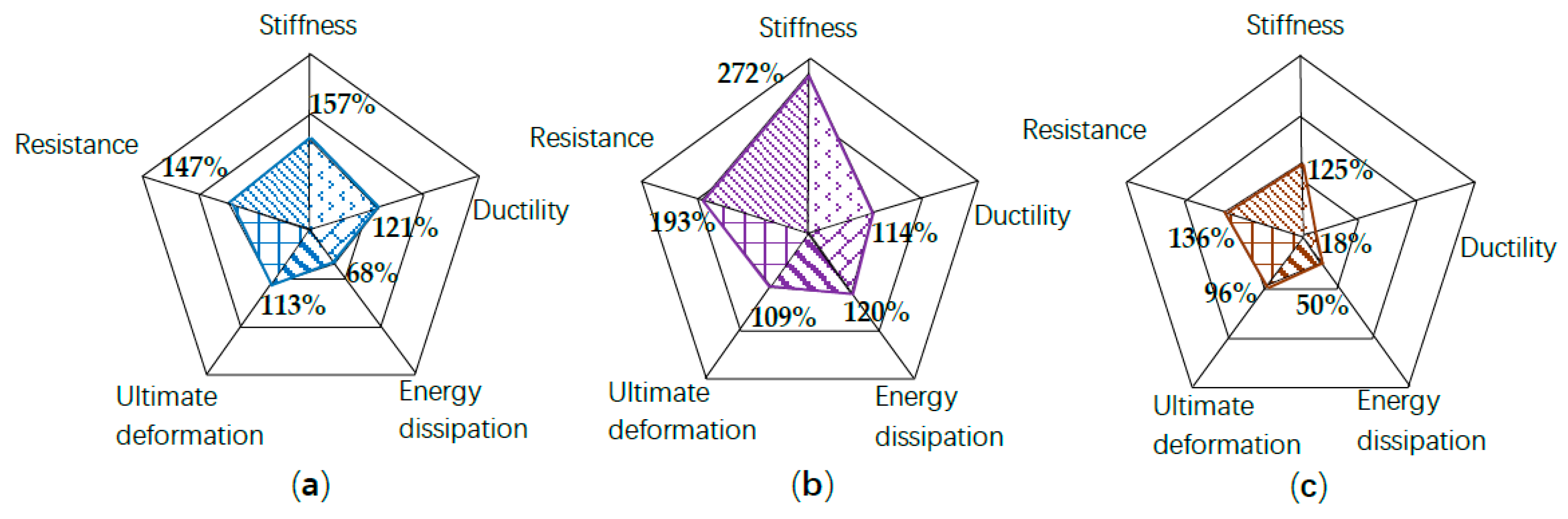
The W1 and W1S deformed similarly at state 1, indicating the UHPC layer had recovered the stiffness of the failed W1. However, the displacement of W1S at state 2 and state 3 is much larger than that of W1, indicating the UHPC layer had postponed the cracking and changed the failure mode. Because of the favorable cooperation between the UHPC layer and the masonry substrate, the ultimate deformation of W1S–which was recovered from the severely damaged W1–increased by 113% than that of W1. Similar result was observed for W2, whose ultimate deformation increased by 109% than that of W1. The difference between the increase of the ultimate deformation of W1S and W2 was less than 4%, indicating the improvement of ultimate deformation was similar for the two walls. The similarity can be explained by the walls’ failure mode. Both W1S and W2 failed in a bed-joint slide mode that was premature and the strengthening layers had not taken full effect. Therefore, the ultimate deformation of W1S and W2 relied much on the resistance of the masonry in their bottom, as explained in
Section 4.3. The resistance of the bottom masonry is similar for W1S and W2, because the W1 had previously failed in a typical shear-compressive mode and its bottom masonry was still in good condition after the failure. The results indicate the UHPC layers significantly improved the deformation ability of the masonry walls.
While, the ultimate deformation of W3 increased by 96% than that of W1. The increase is less than that of W1S and W2 because the UPCP layers deformed with the masonry substrates better than the reinforced polymer layer did, as explained in
Section 4.2 and Figure 14. Besides, the W3 had a large displacement at the bottom when it failed, indicating a severe bed-joint slide.
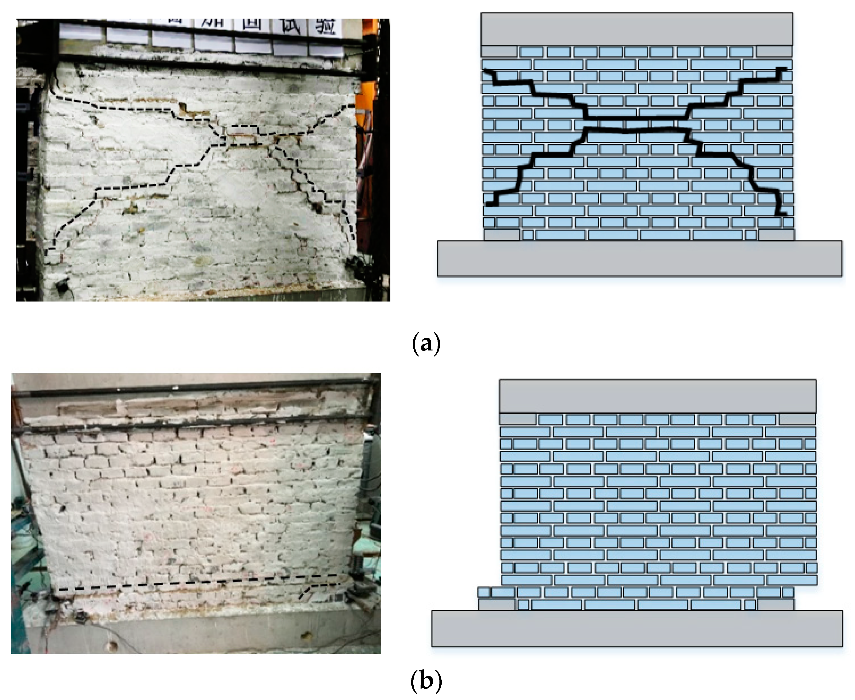
There were two failure modes of the walls, as shown in
Figure 7. The unstrengthened W1 failed in a typical shear-compressive mode, like most load-bearing walls with weak mortar joints. Cracks originated when the lateral force was only 18 kN, and crossing cracks formed when the lateral force was only 35 kN. In the subsequent load cycles, lateral deformation of the wall increased significantly. It failed suddenly when the lateral force was 41.4 kN, and then the force of the actuator dropped.
For the strengthened walls W1S, W2, and W3, horizontal cracks formed and developed at their bottom along with the increase of the lateral forces, and the walls failed through bed-joint slide finally. The horizontal cracks of the W1S, W2, and W3 formed at their bottom when the lateral forces were 32.4 kN, 40.8 kN, and 31.0 kN respectively, which were much higher than that of the cracking load of W1. No severe cracks formed in other parts of the walls after the horizontal cracking, until the walls failed through bed-joint slide suddenly. Such a failure mode of strengthened historical masonry walls hardly happens for strengthened regular masonry walls, for which debonding of the externally bonded layers or strips is the typical failure mode.
3.2. In-Plane Shear Resistance
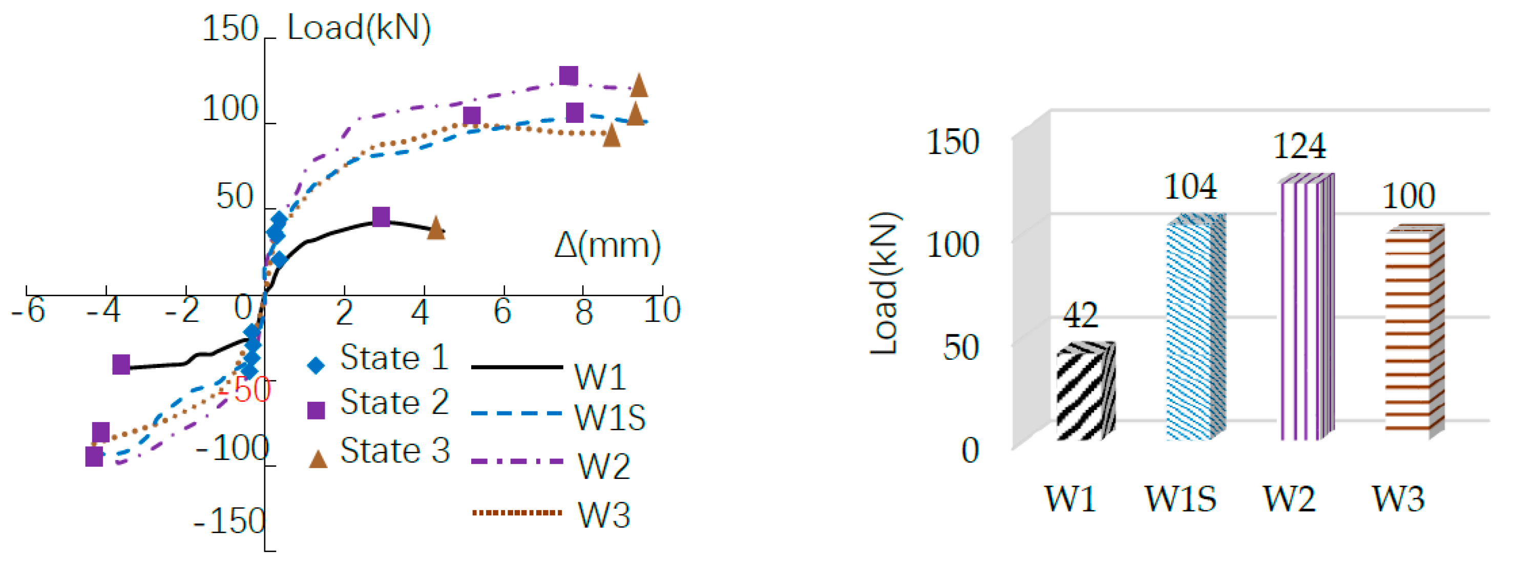
The skeleton curves the walls are illustrated in
Figure 8. The in-plane shear resistance of W1 was low because the historical bricks and mortar were weak. Moreover, irregular shapes of the historical bricks resulted in complicated interactions between the bricks and the surrounding mortar. Failure was more prompt to happen under the combined effect of shear stress, compressive stress, and extra stress introduced by the strain difference between the bricks and the mortar. The wall cracked and crushed severely and lost integrity when it failed. Although it was crushed and split into several parts, the UHPC layer effectively rehabilitated it. The in-plane shear resistance of W1S, which was constructed by strengthening the crushed W1, was 147% higher than that of W1.
The W2 was strengthened by the UHPC layer before loading, and it had the highest in-plane shear resistance within all the walls. Its resistance was 193% higher than that of W1. It shows that the applied UHPC layer also improved the resistance of the masonry wall that has visible but not severe damages.
The W3 was strengthened by the reinforced polymer mortar layer before loading. Its in-plane shear resistance increased less than that of W2 and W1S.
3.3. Stiffness Degradation
Secant stiffness of the walls in each load cycle can be calculated as follows,
where,
and
are the secant stiffness during positive and negative loading in the
ith cycle, respectively;
and
are the maximum lateral forces during positive and negative loading in the
ith cycle, respectively; and
and
are the deformation corresponding to the maximum lateral forces.
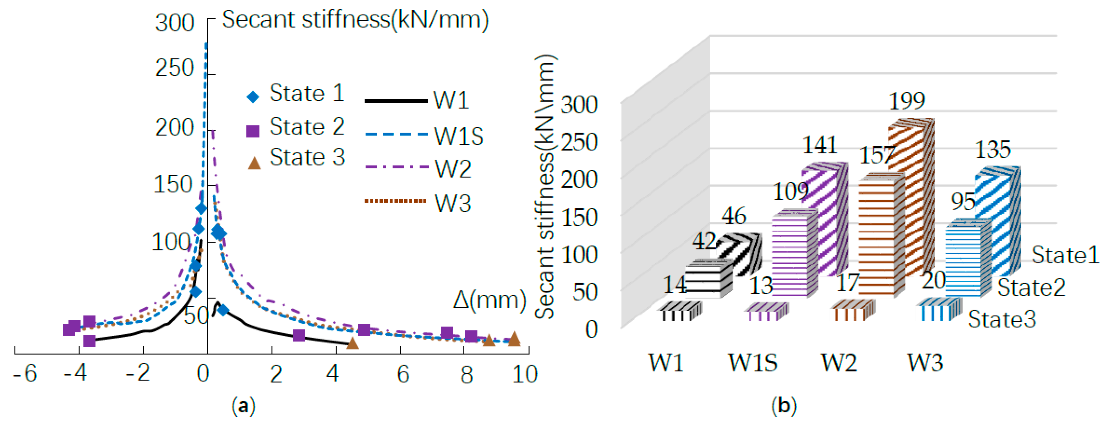
The secant stiffness of the walls decreased at different pace along with the increase of lateral forces, as shown in
Figure 9. The secant stiffness dropped dramatically before state 1, indicating the existing damages in the bricks, the mortar, and the brick-mortar interface were very sensitive and could develop significantly under very small lateral forces. After dropping to a low level at state 1, the secant stiffness degraded gradually.
The strengthened walls retained their stiffness in a rather long deformation procedure before they failed, indicating the UHPC layers and the reinforced polymer mortar layer took obvious effect after state 1 and the walls’ integrity was rehabilitated.
3.4. Ductility and Energy Dissipation
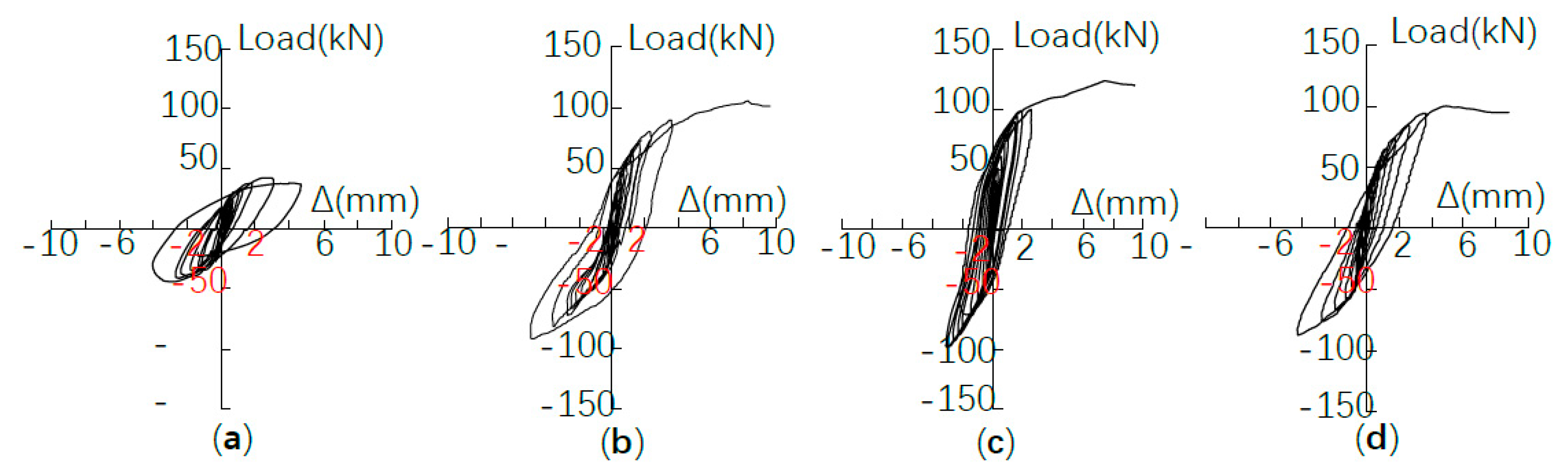
The ultimate deformation of the strengthened W1S, W2, and W3 was 113%, 109%, and 96% higher than that of the unstrengthened W1, and the area of the hysteretic loops of the strengthened W1S, W2, and W3 was 68%, 120%, and 50% higher than that of the unstrengthened W1, as shown in
Figure 10. The results indicate that the strengthened walls dissipated more energy before failure. The UHPC layers improved the energy dissipation ability of the masonry walls, whether the wall was in good condition as the W2 or had been severely damaged as the failed W1.
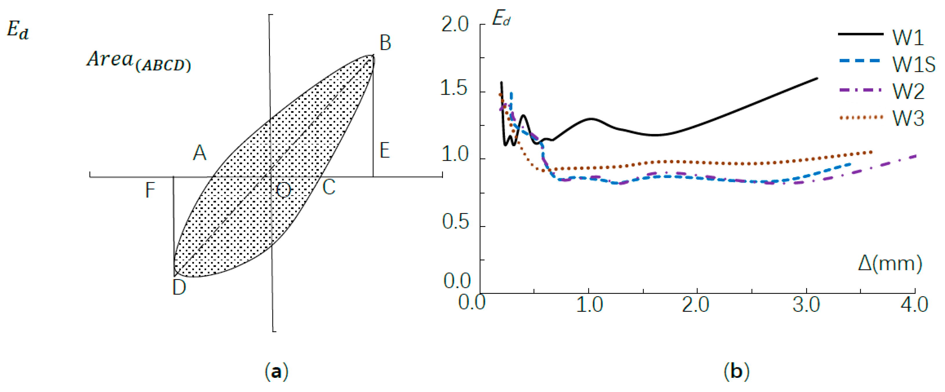
Although the hysteretic loops of the strengthened walls surrounded more area, they were not plump. Therefore, the increase of energy dissipation mainly resulted from the increase of resistance, and the strengthened walls’ energy dissipation ability was not as favorable as their in-plane shear resistance. This can be illustrated by
Figure 11, in which the energy dissipation coefficient equals the area of the shaded part ABCD divided by the sum of the area of the triangle OBE and triangle ODF. The enhancement of energy dissipation had been reversed by the premature bed-joint slide failure, in which the strengthening layers had not taken effect sufficiently.


