1. Introduction
Industrial robotics with advanced technology for the industrial automation field has received considerable attention in recent years [
1,
2,
3,
4,
5,
6]. Although the development and application of industrial robots are confined—to a certain extent—to the field of advanced manufacturing due to the lack of rigidity and precision of an industrial robot compared to a numerical control machine, the industrial robot, as a common and less expensive alternative to the latter, has great advantages and potentials especially in some applications that require low cutting forces, low precision requirements, large-sized complex shaped parts and/or multi-faces machining in one setup. Therefore, industrial robots were extensively invented and introduced into factories for robotic machining and other applications such as spray automation, spot welding and materials handling. Such robotic automation freed humans from heavy and tedious labor and such industries rapidly retooled their manufacturing lines into robot-integrated systems. Consequently, industrial robots offer a real gain of flexibility, modularity, and access for machining on production lines, and are viable solutions for enhanced productivity, quality, and safety. Industrial robotics are being widely adopted in the robotic machining applications and have become an area of significantly in-depth robotics research. More recent research on robotic machining and many diverse research domains have been investigated in recent years [
7,
8,
9,
10,
11,
12,
13,
14].
Several studies were concentrated on five-degree-of-freedom (five-DOF) hybrid robot manipulators for machining and fabrication applications. A five-DOF hybrid mechanism was developed, which included a synthesized two translational DOF and one rotational DOF (2T1R) parallel module [
15]. A five-DOF hybrid mechanism which consists of a 3-DOF parallel platform and a X-Y table [
16]. A parallel mechanism (3T1R) and a rotational table were integrated into a five-DOF hybrid robot manipulator [
17]. A five-DOF hybrid mechanism was designed which includes a parallel manipulator (2T1R) with a rotational table [
18]. A five-DOF hybrid mechanism including a 2-DOF redundant parallel manipulator was developed [
19]. A five-DOF hybrid mechanism was investigated, consisting of a 3-DOF parallel manipulator with actuation redundancy and a 2-DOF worktable [
20]. A five-DOF hybrid robot was introduced, which comprises of a parallel mechanism (1T2R) and two gantries [
21]. Two five-DOF mechanisms were introduced, which are composed of a 3-DOF parallel mechanism connected in series with a 2-DOF wrist [
22]. Some of the designs of these five-DOF hybrid robot manipulators are complex, since an application of the inferior-mobility robot manipulator demands a translatable table [
15] or a rotatable one [
16,
17,
18]. Also, the problem of achieving motion control is harder for a hybrid mechanism [
19,
20] with redundantly actuated joints than a non-redundantly actuated one. Moreover, a relatively small workspace for a robot manipulator is established to perform tasks [
22].
Several research works are concentrated on the related technologies of robotic deburring. Practical mechanical deburring methods, including robotics for aluminum work parts and an overview of burr formation mechanism and morphology, were presented, and several deburring classifications were also proposed [
23]. Also, a review of burr formation modeling and control, and factors governing milling burr formation were presented [
24]. Robotic application of edge deburring with a controlled force progression pneumatic tool for a part of the manufacturing process of an aircraft engine detail was investigated [
25]. A flexible robot-based cast iron deburring cell using a single-point laser displacement sensor was developed for small batch production of a robotized deburring task in a standard cast iron foundry scenario [
26]. An adaptive robotic system using a custom-developed 3D laser-triangulation profilometer was developed for the robotic deburring of die-cast parts with position and orientation error correction [
27]. Through discrete event simulation and 3D digital human modeling, a multi-purpose digital simulation approach was proposed for the sustainability enhancement of a real manufacturing cell of the aerospace industry, automated by robotic deburring [
28].
The current research and applications of robotic deburring are mainly carried out by one or more traditional and commercial six-degree-of-freedom (six-DOF) serial industrial robot manipulators, which are not always suitable for the robotic deburring of complex shaped parts with highly dexterous orientations adjustment and efficient multi-faces deburring in one setup because of the defective nature of this kind of serial robot manipulator, e.g., the weakened structural rigidity of the extended robot manipulator when it is reaching far deburring position with a cantilever-beam-like structure, and the poor accessibility and small safety margins between robot manipulator and workpiece resulting from its difficulties in both obstacle avoidance adjustment and deburring orientation adjustment.
Several studies investigating tool path adaptation and process parameter control for robotic deburring were presented. A tool path adaptation for robotic deburring was presented in accordance with the registration using a custom 3D laser-triangulation profilometer to compensate the positioning errors of the currently processed workpiece, which is difficult to ensure repeatable clamping [
27]. A tool path modification method based on a computer-aided design model and direct teaching was proposed to compensate for the position/orientation errors of the workpiece, in addition, impedance control was used to avoid applying an excessive contact force and a virtual wall was adopted to improve the force-control performance for the robotic deburring process [
29]. An application of a human mimicking control strategy that mimics the human behavior during the manual deburring on the deburring of hard material items using an industrial robot was introduced [
30]. By satisfying a set of constraints to properly perform the desired surface contact conditioning, a hybrid position/force control approach using task priority and sliding mode control was proposed for contact-driven robotic surface treatments such as deburring [
31,
32]. A set of optimal process parameter combination for robotic machining and the effect of process parameters such as spindle speed, feed rate and tool path strategies on the performance characteristics were investigated using the Taguchi–Grey relational approach and analysis of variance [
33]. Edge robotic deburring with a controlled force progression pneumatic tool, as well as a methodology used to select and optimize the edge robotic deburring process, was presented [
25]. A sliding mode control method based on radial basis function neural network was proposed for the deburring of industry robotic systems, without the requirements for strict constraints, an accurate model and exact parameters [
34]. A fuzzy proportional–integral–derivative (PID) control method for deburring industrial robots was proposed and the PID controller parameters can be updated online at each sampling time to allow adaptive compensation for error and guarantee trajectory accuracy of the end-effector [
35]. A vision-based approach, a Pythagorean hodograph quintic spline interpolator based on S curve acceleration/deceleration and an integrated process control structure consisting of an adaptive disturbance compensator, a sliding mode controller, and a friction compensator were investigated for force control and contour following in industrial applications such as deburring [
36].
These studies of tool path adaptation and process parameter control for robotic deburring are usually conducted on one or more traditional and commercial six-DOF serial industrial robot manipulators. The tool path adaptation for robotic deburring implemented usually needs to supplement extra equipment or processes, e.g., using a vision system described in [
27,
36] or direct teaching [
29]. Other studies on the process parameter control for robotic deburring have certain constraints, e.g., the deburring tool is an abrasive diamond disc in the control strategy for the process parameter control, and other deburring tools are not considered [
30]; the designed control action and implementation are more intricate, such as [
25,
31,
32,
34,
36]; the procedure of the proposed approach is more complicated, such as [
33]; or detailed deburring process parameters such as robotic feed and spindle speed for the deburring industrial robot are not considered [
35].
The deburring orientation adjustment of current industrial robots is usually not dexterous, especially at the far deburring position while simultaneously considering obstacle avoidance. There is an urgent need to develop a robot manipulator for robotic deburring of complex shaped parts with highly dexterous manipulation and very efficient five-face deburring in one setup. Moreover, there are very few related references for the tool path strategies which are implemented as proprietary software packages of robot manufacturers. It is particularly necessary to conduct the research on the tool path planning which is highly suitable for the deburring characteristics of the self-developed robot manipulator. Also, in order to perform an adaptive deburring process and finer deburring quality, it is very important to investigate an easy-to-implement and efficient process parameter control method with automatic-online errors correction.
The rest of this article is organized as follows. The structure of the robot manipulator and related research are described in
Section 2. A robotic deburring tool path planning method and a robotic deburring process parameter control method are proposed for robotic deburring in
Section 3 and
Section 4, respectively. A dexterous manipulation verification experiment is presented in
Section 5. Two robotic deburring experiments, disc deburring experiment of an automobile hub and multifaceted edges deburring experiment of an automobile steering booster housing, are conducted in
Section 6. Finally, conclusions are drawn in
Section 7.
2. Structure Description and Related Research of the Robot Manipulator
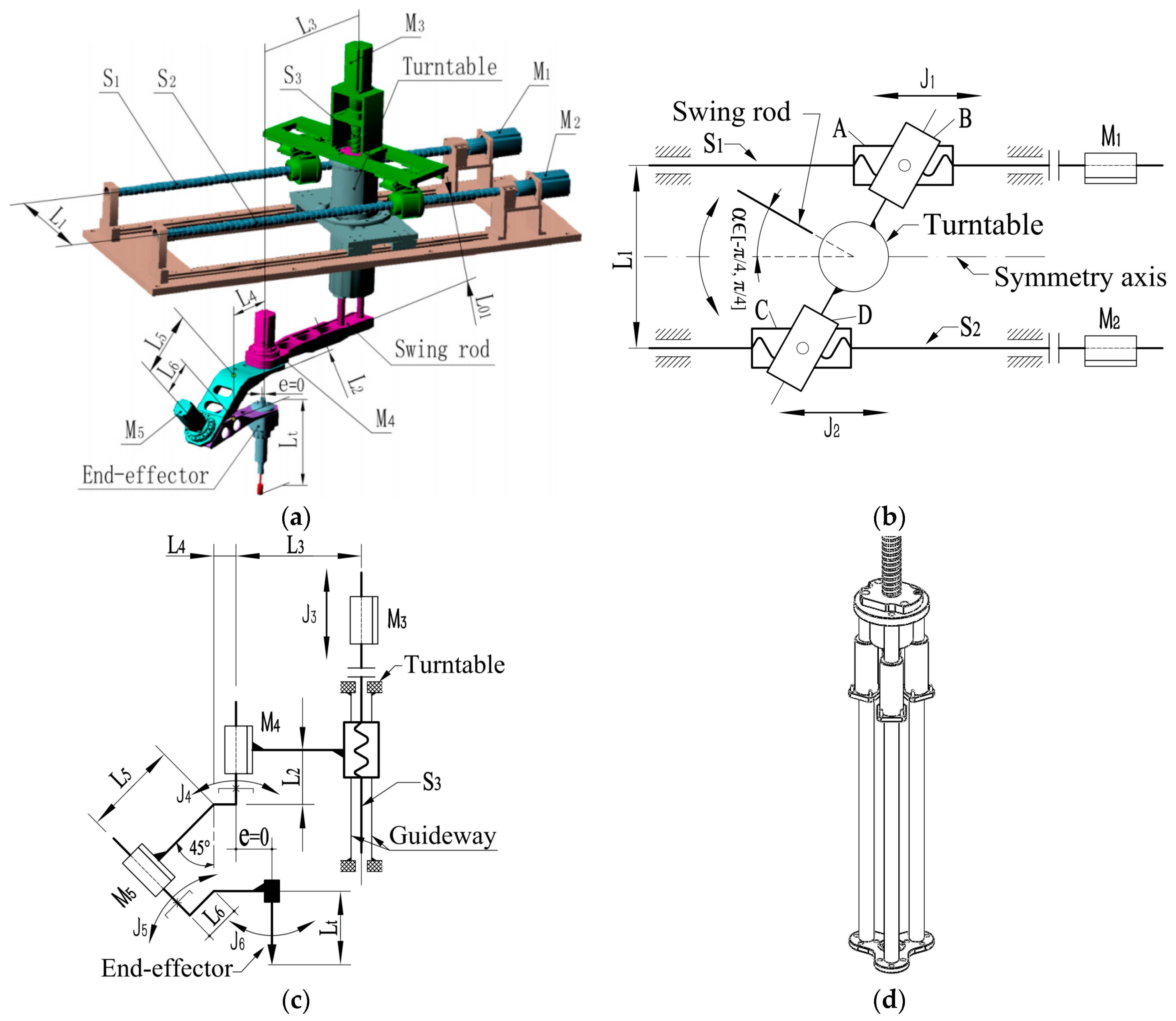
This section outlines the structure, experimental platforms and previous theoretical research of a developed five-degree-of-freedom (five-DOF) hybrid robot manipulator. The structure of the robot manipulator is shown in
Figure 1. The robot manipulator, consisting of a 3-DOF (3T) parallel module and a 2-DOF (2R) serial module, is a newly developed 3T2R hybrid robot manipulator. The first three translational motion axes
J1,
J2 and
J3 (consisting of ball screws) are driven by motor
M1,
M2 and
M3, respectively. The last two rotational motion axes
J4 and
J5 are driven by motor
M4 and
M5, respectively. The axis
J6 is the end-effector which contains a high-speed motor spindle. The designed structure parameter
e is equal to zero, and the available range of the rotation angle is
because of the mechanical constraints.
One of the most significant advantages of the robot manipulator is its dexterity in manipulation and orientation reachability. The last two rotational motion axes
J4 and
J5 as shown in
Figure 1 are connected with an angle of 45° in order to realize the dexterous manipulation and the orientation adjustment of the robot manipulator end-effector. The end-effector can reach all orientations in the upper half of the complete spherical surface. Hence, the robot manipulator has the five-face machining ability in one setup. The detailed realizations are described as follows.
When the processing point of the end-effector coincides with the intersection of axes J4 and J5, the position of the processing point of the end-effector can always keep at a same point (i.e., this point always coincides with the intersection), during the process of orientation adjustment in the upper half of the complete spherical surface only through the last two axes J4 and J5. And the position of the processing point can be adjusted when translating the first three axes J1, J2 and J3. This means that the manipulation and the orientation reachability of the robot manipulator characterize a very high level of dexterity.
It is necessary to note that some nonnegligible dynamic effects which caused by backlash of ball screws and robot manipulator structural deformations. It is very meaningful to investigate these effects of the backlash and structural deformations and to compensate for them if necessary. Some related research can be referred to [
37,
38,
39,
40].
Experimental platforms of the robot manipulator are shown in
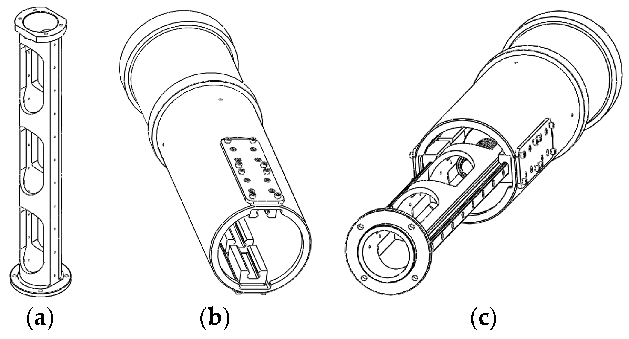
Figure 2. Among them, the improved platform is superior to the original one in mechanical structure on translational vertical axis assembly. The cylinder guide pillar module (shown in
Figure 3c) of the improved platform, and the guideway module (shown in
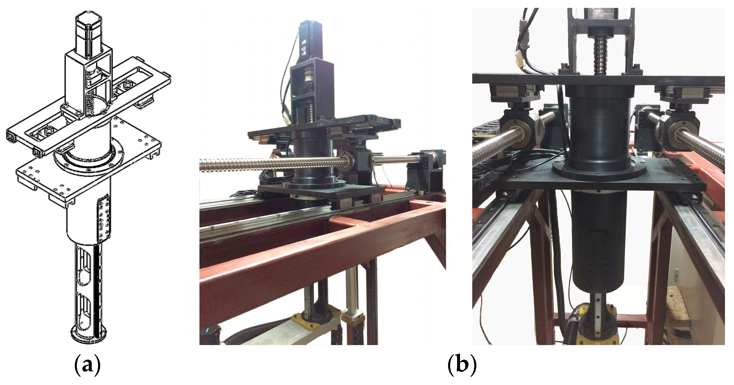
Figure 1d) of the original one, are constituted by cylinder guide pillar and cylinder type support, and three sets of linear shafts and linear bearings, respectively. The former has greater torsional rigidity and strength of the vertical axis assembly around the vertical rotation axis than the latter. Finally, design structure and physical structure of the vertical axis assembly for the improved platform are shown in
Figure 4.
The reachable workspace of the robot manipulator based on structure parameters (
Table 1) is shown in
Figure 5. The top view and the front view of
Figure 5 showed the range in the X, Y, and Z direction of the reachable workspace. Note that the shapes of the left end and the right end (in the top view of the
Figure 5) are different. This is caused by the sway of the swing rod. The sway values are
L3cos
and
L3sin
in the
X and
Y directions, respectively. In the start phase,
increases from zero to the maximum attainable value (
), and the sway value in the
X and
Y directions gradually decrease and increase, respectively. In the end phase,
decreases from the maximum attainable value (
) to zero, and the sway values in the
X and
Y directions gradually increase and decrease, respectively. The mutual variation relationship is shown in
Figure 5a.
In the previous research, kinematics analysis, dynamics analysis, dexterity analysis, multi-objective smooth trajectory planning and dynamic load-carrying capacity calculation, actual building of mechanical system and motion control system, and tests for the repeatability and accuracy of both the position and path for the five-DOF robot manipulator are conducted. For discussions of these domains and a more detailed listing of related research for the robot manipulator, see [
41,
42,
43,
44].
3. Robotic Deburring Tool Path Planning Method
In this section, a robotic deburring tool path planning method is proposed to handle the robotic deburring tool location (position and orientation) planning and the robotic layered deburring planning for the developed five-DOF robot manipulator.
In this article, the theoretical curve and theoretical surface, which are expected to be qualified after the final robotic deburring, are called the target curve and target surface, respectively. The deburring tool is a general term for various deburring tools, including the cutting tool with the end or side face edge, and the grinding tool such as grinding wheel head and rotary file.
3.1. Robotic Deburring Tool Planning Method
The proposed robotic deburring tool position planning method is discussed in two parts: surface deburring and curve deburring. In the first part (i.e., surface deburring), the tool contact path intersection line method [
45] is used to generate the contact position of the deburring tool, i.e., the total locus of deburring tool contact points are derived from the intersection of a set of equidistant constraint planes and the target surface. Among them, the constraint plane spacing, the line spacing and step length of the tool path should be determined by some comprehensive factors such as deburring tool, deburring accuracy, deburring efficiency and deburring error. In the second part, i.e., curve deburring, the above comprehensive factors are also considered to directly generate the total locus of discrete deburring tool contact points. Upon obtaining the total locus of deburring tool contact points for surface deburring and curve deburring, considering the curvature variations of the surface and the curve, respectively, the total locus of deburring tool contact points is offset according to the layered deburring planning. After that, the deburring tool path of each layer is generated with some practical considerations of deburring tool length, blade edge and blade diameter, etc.
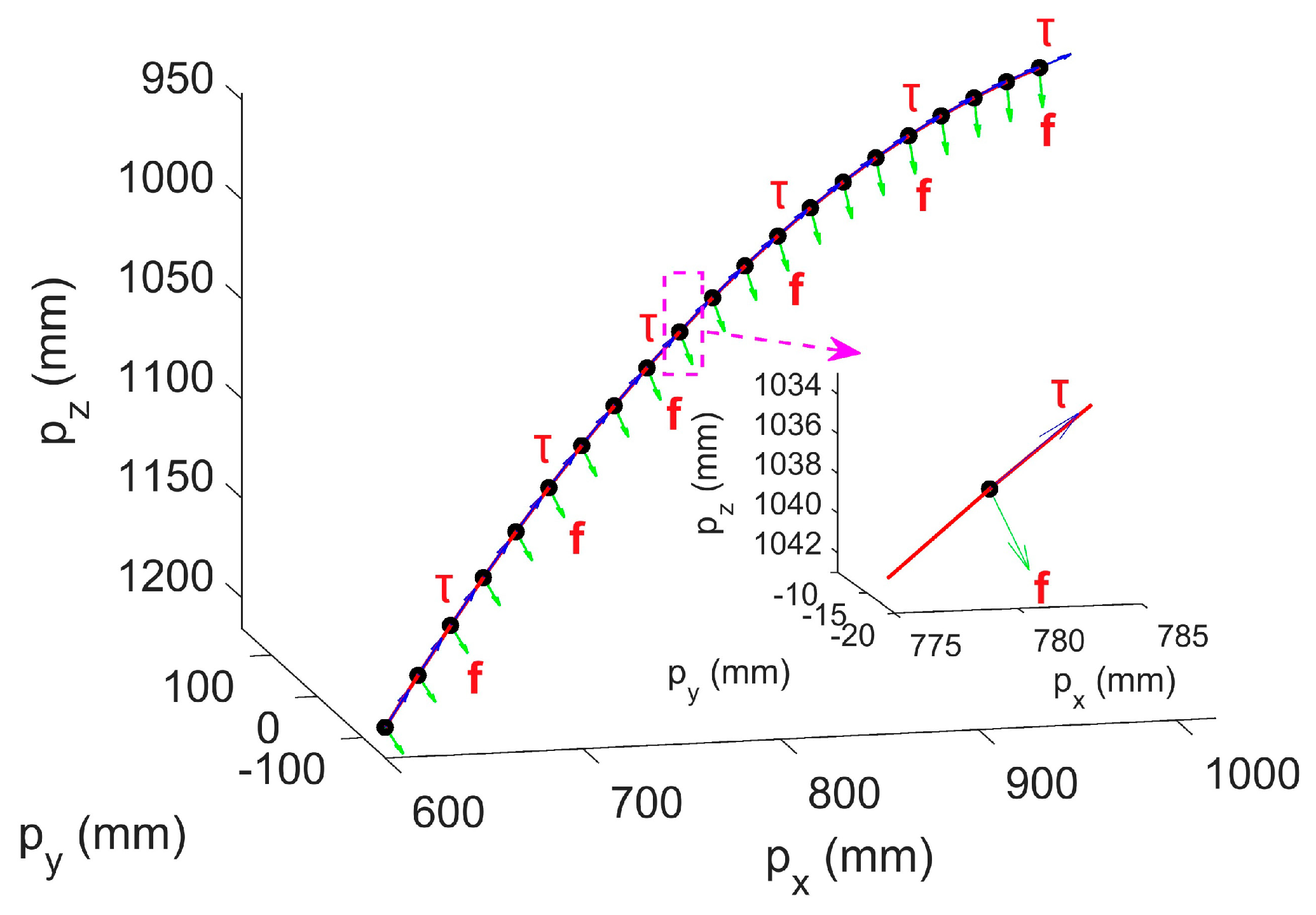
In this article, the orientation of the deburring tool is aligned with its side edge, defined as follows. Deburring tool orientations, the movement direction of the tool and the end edge of the tool are expressed as vectors
,
and
, respectively. A target curve is used as an example to illustrate the robotic deburring tool orientation planning method. The target curve is shown in
Figure 6, and unit tangent vectors
and unit inner normal vectors
of discrete positions are represented by blue arrows and green arrows, respectively.
The proposed robotic deburring tool orientation planning method is proposed for deburring manners with the tool end edge and the tool side edge. The assignment of orientation vectors for these two deburring manners is described as follows. For the tool end edge (i.e., the deburring manner with the tool end edge): (a) the deburring direction of tool is planned along the tool end edge vector , which is chosen as the unit inner normal vectors of each discrete position of the target curve; (b) the movement direction of tool (vector ) is planned along the unit tangent vectors of each discrete position of the target curve and points to the next discrete position to be deburred; and (c) the tool vector is obtained by . For the tool side edge (i.e., the deburring manner with the tool side edge): (a) the deburring direction of tool is planned along the tool side edge vector , which is chosen as the unit inner normal vectors of each discrete position of the target curve; (b) the planned movement direction of tool (vector ) is the same as above deburring manner; and (c) the tool vector is obtained by .
In the above robotic deburring tool orientation planning, the feeding direction of the robot manipulator deburring corresponds to the deburring tool direction of the end edge or the side edge, that is, the feeding directions of the robot manipulator deburring along the unit inner normal vectors for discrete positions of the target curve. The movement direction of the robot manipulator deburring corresponds to the movement direction of the tool, that is, the movement directions of the robot manipulator deburring along the unit tangent vectors for discrete positions of the target curve.
3.2. Robotic Layered Deburring Planning Method
The feature points on the object are selected based on the geometric characteristics of the deburring target, and the machining allowances are measured by the distance between each selected feature point and the target curve and/or surface. The detailed description of the proposed robotic layered deburring planning method for the layered deburring curve and/or surface is presented in the following steps:
Step 1: calculate the distance between each selected feature point and the target curve and/or surface, and find out the maximum one (which is denoted as ) as the maximum machining allowance for the layered deburring curve and/or surface.
Step 2: calculate the number of deburring layers (i.e., the times of layered deburring) by the formula , where and symbolic form represent the thickness of each selected deburring layer (i.e., cutting depth) and the rounding calculation, respectively. In order to improve the deburring quality, the deburring count is calculated based on different allowance in the last layer: (a) set it to one when and the deburring allowance sets , and (b) set it to two when , here, the first deburring allowance sets , and the second one sets the remains (i.e., ).
Step 3: plan the deburring tool path on each layer (i.e., the total locus of deburring tool contact points between the deburring tool and the object) based on the index of each layer
and its corresponding thickness
, that is, calculate the position offset relationship of each layer for points of the deburring tool path along the outward normal vector
of each discrete point derived from the target curve and/or surface (i.e., the deburring tool contact positions on the target curve and/or surface are obtained by the tool contact path intersection line method [
45]), as follows:
where, when
,
and
represent the number of located layer of the target curve and/or surface and positions of each discrete point of the target curve and/or surface, respectively. And the incremental position calculation is related by
Step 4: conduct the semi-finishing and finishing based on actual and special requirements according to Step 2 and Step 3.
Step 5: introduce the orthogonal overlapping and reciprocating manner, and the shape of the basic body surface that is connected with the target curve to conduct planning the deburring tool path for surface deburring and curve deburring at each layer.
In the above-mentioned deburring tool path planning for surface deburring and curve deburring, if the feature points of the object are unknown beforehand, the maximum machining allowance can be estimated by the robot manipulator teaching according to the actual workpiece to be deburred, and the remaining planning steps are the same as above.
Usually, the loci of deburring tool contact points, which are obtained by only using the offset computed from the tool contact path intersection line method [
45], may cause a large machining error due to the equal-distance offset. Compared with this tool contact path intersection line method [
45], the proposed robotic deburring tool planning method for tool position and tool orientation in this section further extends to consider the curvature variations of the surface and the curve on the basis of this tool contact path intersection line method with the equal-distance offset, so as to ensure a more uniform deburring tool trajectory and repair these deficiencies caused by this method [
45].
Please refer to the related documents for detailed explanation of machining mechanism and machining principles for topics such as deburring tool selection and its corresponding robotic deburring feed speed and tool spindle speed for different deburring workpieces with different curves or curves.
4. Robotic Deburring Process Parameter Control Method based on Fuzzy Control
A robotic deburring process parameter control method of the five-DOF robot manipulator for robotic deburring is proposed in this section. This proposed method is adopted in deburring process parameter adjustment control for the stable robotic deburring with a constant cutting speed and a constant cutting force via a designed fuzzy controller.
According to metal cutting principle, the cutting parameters include cutting speed, cutting feed and cutting depth. Taking carbide turning tools for carbon steel turning as an example, related researches showed that the biggest impact on tools is the cutting speed, followed by the cutting feed, and lastly the cutting depth [
46,
47,
48]. More generally, the rough machining should select cutting parameters for the maximum productivity. Thus, a larger cutting depth (or cutting width) should be selected first, and after the majority of the machining allowance is removed, a suitable cutting feed (or a cutting thickness) and a cutting speed are selected in turn by the cutting condition. Finish machining generally uses a small cutting depth and cutting feed, and then a higher cutting speed to improve the machining accuracy and reduce the surface roughness.
In this article, robotic deburring process parameters—robotic spindle speed, robotic feed and robotic layered deburring thickness—are determined by cutting parameters—cutting speed, cutting feed and cutting depth—respectively. Among them, the robotic layered deburring thickness (i.e., cutting depth) planning and the robotic deburring tool location (position and orientation) planning are presented in the proposed robotic deburring tool path planning method in
Section 3. In this section, issues to consider here pertain, mostly, to the adjustment control for robot manipulator deburring process parameters, that is robotic spindle speed and robotic feed, through a proposed robotic deburring process parameter control method.
Some classical control methods, such as proportional–integral–derivative (PID) control, which have been studied and practiced by broad researches, are very effective solutions for uncomplicated linear time-invariant systems [
49,
50,
51]. In addition, modern control theory, such as sliding mode control, based on state variables has also been widely used to solve linear or nonlinear, and time-invariant or time-varying multi-input multi-output (MIMO) systems [
52,
53,
54]. Although this kind of classical and modern control theory can overcome some internal disturbances of the control system, nevertheless, it is neither sufficient to ensure the stability of robotic deburring process in a robust enough way in real time, nor able to cope with environmental uncertainties. One goal of this article is to find a way of controlling the robotic deburring contact forces while maintaining constant cutting speed and cutting force of the robot manipulator presented earlier. In particular, this is critical when the interaction between the robot manipulator and deburring workpiece environment is of concern.
Because the fuzzy control with the ontological basis of fuzzy logic and fuzzy reasoning has the advantage of requiring neither the knowledge of the model structure nor the model parameters, it is strongly adaptive and highly robust to nonlinearity and variations of process parameters. Also, it can give fast response, effective noise suppression, and a better control effects when the model structure changes greatly. Therefore, related researches and applications based on fuzzy control have been favored by many scholars [
55,
56,
57,
58].
In this article, the process of the adjustment control for robot manipulator deburring process parameters (i.e., robotic spindle speed and robotic feed) has the characteristics of nonlinearity, noise and tight coupling between control loops, which cannot be solved sufficiently by classical and modern control methods such as PID-type controllers. In this section, a fuzzy controller with the above advantages of the fuzzy control is designed for a proposed robotic deburring process parameter control method to systematically accommodate robotic deburring.
The control objectives of the designed fuzzy control system in this section are the robot manipulator deburring process parameters, i.e., robotic spindle speed and robotic feed. The robotic spindle speed and the robotic spindle load of the robot manipulator deburring system can be controlled by adjusting the control voltage of the robotic spindle and the robotic feed, in order to realize the robotic deburring with a constant cutting speed and a constant cutting force. Hence, the designed fuzzy controller in this section is a two-input and two-output control system (shown in
Figure 7). Here, input variables are robotic spindle speed and robotic spindle load, and output variables are control voltage of the robotic spindle and robotic feed.
In this article, a parallel structure adopted is used by the fuzzy controller to independently control the control voltage of the robotic spindle and the robotic feed. There are two parts of representing fuzzy variables in the designed fuzzy controller. First, error of robotic spindle speed and change in error of robotic spindle speed , and error of robotic spindle load and change in error of robotic spindle load , are represented as input fuzzy variables for controlling the control voltage of the robotic spindle and the robot feed, respectively. Second, change in control voltage of the robotic spindle and change in robotic feed are represented as output fuzzy variables.
To achieve discrete membership functions, a discrete set with thirteen elements and a discrete set with seven elements are defined in the designed fuzzy controller for
,
, and
, and for
,
, and
, respectively, and corresponding sets are
and
, respectively. Assume that variation ranges of
,
,
and
are
,
,
and
, respectively. Combining these variation ranges and corresponding discrete sets, several quantizers corresponding to
,
,
and
are defined respectively as follows:
Here, each quantizer maps an inbound measurement within the variation range to a nearest integer element in the corresponding discrete set.
Similarly, scaling factors for the output variables (i.e., control variables) of
and
, where corresponding variation ranges are
and
, respectively, are defined as follows:
Assuming exact values obtained by the fuzzy reasoning for change in control voltage of the robotic spindle
and change in robotic feed
are
and
, respectively, then corresponding exact values of variation ranges
and
can be obtained by using above defined scaling factors. The detailed representations are given by
The fuzzy rule with automatic adjusting factors in the whole set using analytical expressions for fuzzy controller are usually designed as follows. Suppose that sets for error
, change in error
and control variable
select as
, the fuzzy rule can be expressed as
where
and adjustment factor
, and symbolic form
represents the rounding calculation. Thus, the designed fuzzy rule can be automatically adjusted on the basis of the weight and magnitude of the error.
In this article, in order to optimize the designed fuzzy controller that provides good both static and dynamic stability properties, and robust performance, fuzzy rules are designed with automatic adjusting factors in the whole set, described by analytical expressions. Thus, in the whole set, weights of errors and changes in errors, which represent the effect on control results, can be automatically adjusted by errors. The detailed fuzzy rules for robotic spindle speed and robotic spindle load are designed respectively as follows:
where
and adjustment factor
, and symbolic form
represents the rounding calculation; and
where
and adjustment factor
, and
represents the same mentioned above.
It can be seen from the above that fuzzy rules are characterized naturally in that the adjustment factors and can be updated online and adjusted by the absolute value of the error and , and there are six and three possible values, respectively, therefore, weights of errors and changes in errors can be automatically adjusted online by errors.
The automatic adjustment process of the above designed fuzzy rules conforms to the control characteristics of the human decision-making process, and these fuzzy rules described by the analytical forms exhibit their several own advantages over other representations in the optimization property, convenience, simplicity, and implementation in real time for fuzzy control algorithms.
5. Dexterous Manipulation Verification Experiment
In this section, an experiment is conducted on the improved experimental platform of the robot manipulator (shown in
Figure 8a) to verify the dexterous manipulation of the robot manipulator, especially the dexterous manipulation of a certain processing point. An aluminum alloy casting automobile steering booster housing (shown in
Figure 8b) was selected as the experimental object, and the dexterous manipulation verification experiment was carried out at the center hole on the cylindrical top of the booster housing (shown in
Figure 8b).
Experimental verification of the dexterous manipulation was carried out on the platform of the improved robot manipulator. When the last two axes
J4 and
J5 both matched the actual initial state (shown in
Figure 8a), the first three axes
J1,
J2 and
J3 were adjusted so that the tool tip of the end-effector reached the center hole on cylindrical top of the booster housing until the intersection of the last two axes
J4 and
J5 basically coincided with the center hole (shown in
Figure 8b). Then the first three axes
J1,
J2 and
J3 remained stationary, and only the last two axes
J4 and
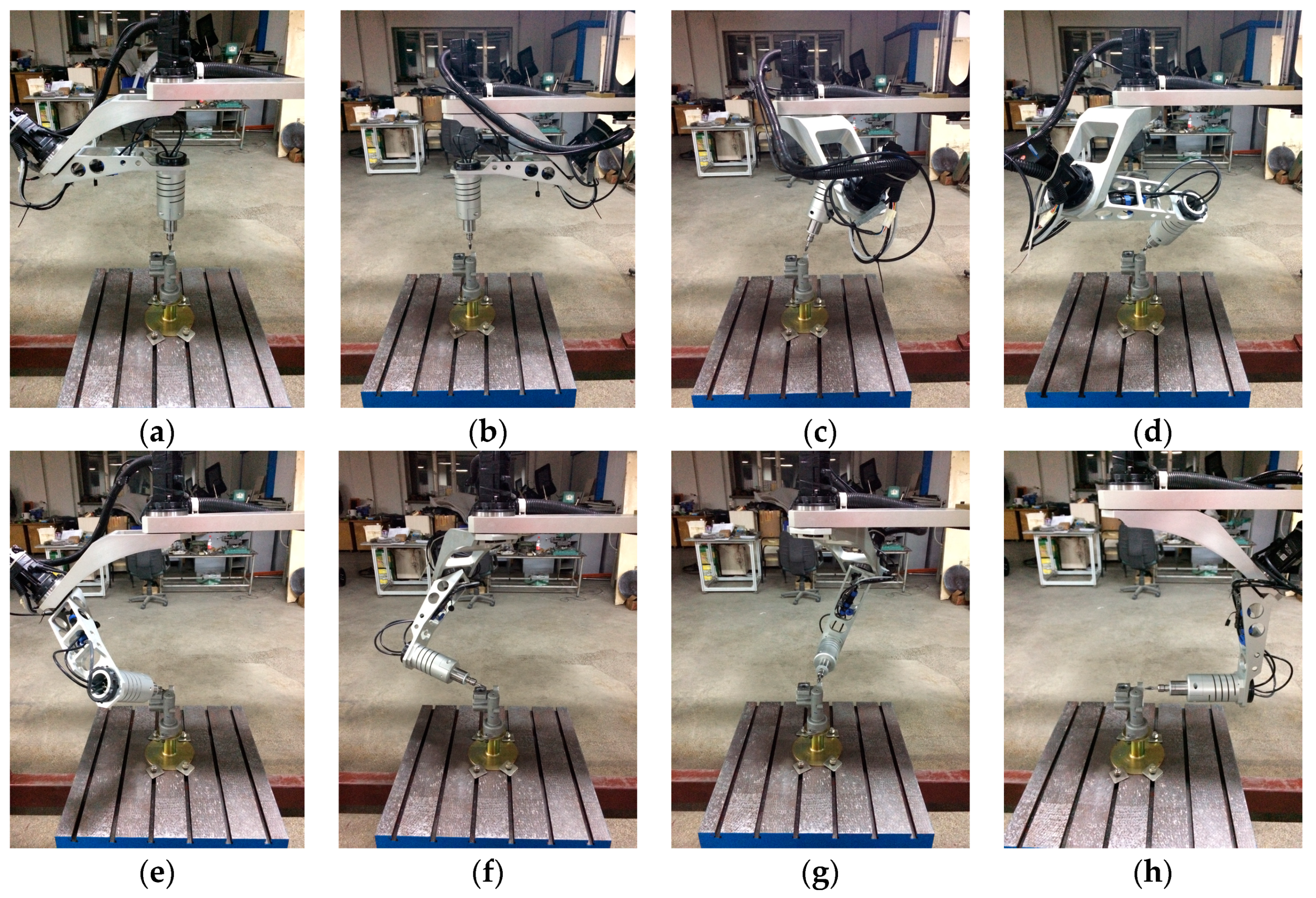
J5 rotated within the motion range. The characterizations of the dexterous manipulation of the robot manipulator are shown in
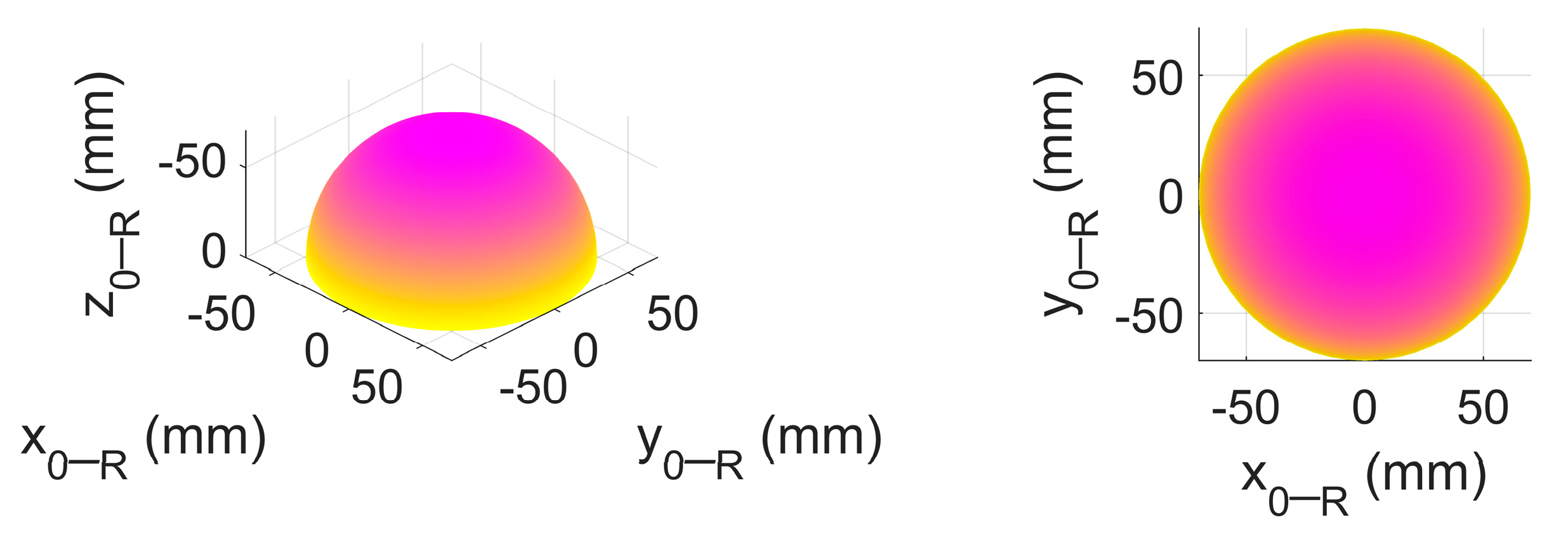
Figure 9. The enveloping surface of the dexterous manipulation verification experiment is shown in
Figure 10.
When the last two axes
J4 and
J5 traversed the motion ranges
and
, respectively, as shown in
Figure 9, it can be found that the total locus of the tool tip of the end-effector appeared as an approximate enveloping half-spherical surface with a downward open, as shown in
Figure 10, and the center of the half-spherical surface was the intersection of the last two axes
J4 and
J5. In addition, the total locus of the tool tip remained the same when the last two axes
J4 and
J5 traversed the motion ranges
and
, respectively. For the sake of simplicity, only the former case is illustrated in
Figure 9. Note that the approximate enveloping half-spherical surface was not a strictly half-spherical surface, and the extremely small difference was caused by the structure parameter
, which was not strictly equal to zero due to assembly errors.
The above results of the dexterous manipulation experiment imply that the robot manipulator has a very high level of the dexterous manipulation and the orientation reachability. These available and excellent characterizations of the dexterous manipulation and the orientation reachability can provide appropriate and flexible manipulations and orientation adjustments with a very high level of dexterity for the robotic deburring of the robot manipulator.
6. Robotic Deburring Experiments
Two robotic deburring experiments were conducted on the experimental platforms of the robot manipulator in this section to show the effectiveness of the proposed robotic deburring tool path planning method and the proposed robotic deburring process parameter control method, and also to demonstrate the superiorly operational manipulation performance and the deburring ability of the robot manipulator.
6.1. Disc Robotic Deburring Experiment
In the first robotic deburring experiment, a disc deburring for an automobile hub was conducted on the original experimental platform of the robot manipulator (shown in
Figure 2a). The experimental workpiece was an aluminum alloy casting blank of an automobile hub, as shown in
Figure 11a, and the experimental deburring object were disc burrs of the automobile hub, as shown in
Figure 11b.
It can be seen from
Figure 11 that disc burrs of automobile hub were located on the inside of the mold cavity, so that these burrs were not suitable to be removed via the abrasive belt grinding. It was a good use case of a certain carbide rotary tool (i.e., a kind of high-speed machining file, shown in
Figure 12) driven by the robot manipulator with a high level of dexterity of manipulation and orientation reachability. Furthermore, this kind of rotary tool with a relatively long side cutting edge is more suitable to execute the deburring for disc burrs of automobile hub. A double-cutting cylindrical round-head carbide rotary tool with the side cutting edge (shown in
Figure 12b and its type is CX1020M06) was selected to carry out the deburring for disc burrs of automobile hub in the first experiment. The length of the side cutting edge and the diameter of the selected tool were 20 mm and 10 mm, respectively.
Based on the proposed robotic deburring tool path planning method, the detailed robotic deburring tool location (position and orientation) planning and the detailed robotic layered deburring planning are presented as follows. The selected tool can deburr once the entire thickness of burrs due to the length of the side cutting edge is significantly larger than the thickness of burrs with range between 0.37 mm and 0.72 mm. Thus, the disc burrs of automobile hub can be removed by executing robotic layered deburring several times through the proposed robotic deburring tool path planning method.
Disc burrs vary in size and exhibit a discontinuous distribution as can be seen in
Figure 11b. Through the actual measurement, the maximum width dimension, i.e., the maximum machining allowance
was 7.36 mm. In the first experiment, the thickness of the single-layer deburring, i.e., the cutting depth
was set as about one third of the diameter of the side cutting edge, which was taken as 3 mm. The entire allowance can be deburred completely by repeating three times. Among them, the thickness of the last deburring layer was selected as 1.36 mm to improve the deburring quality.
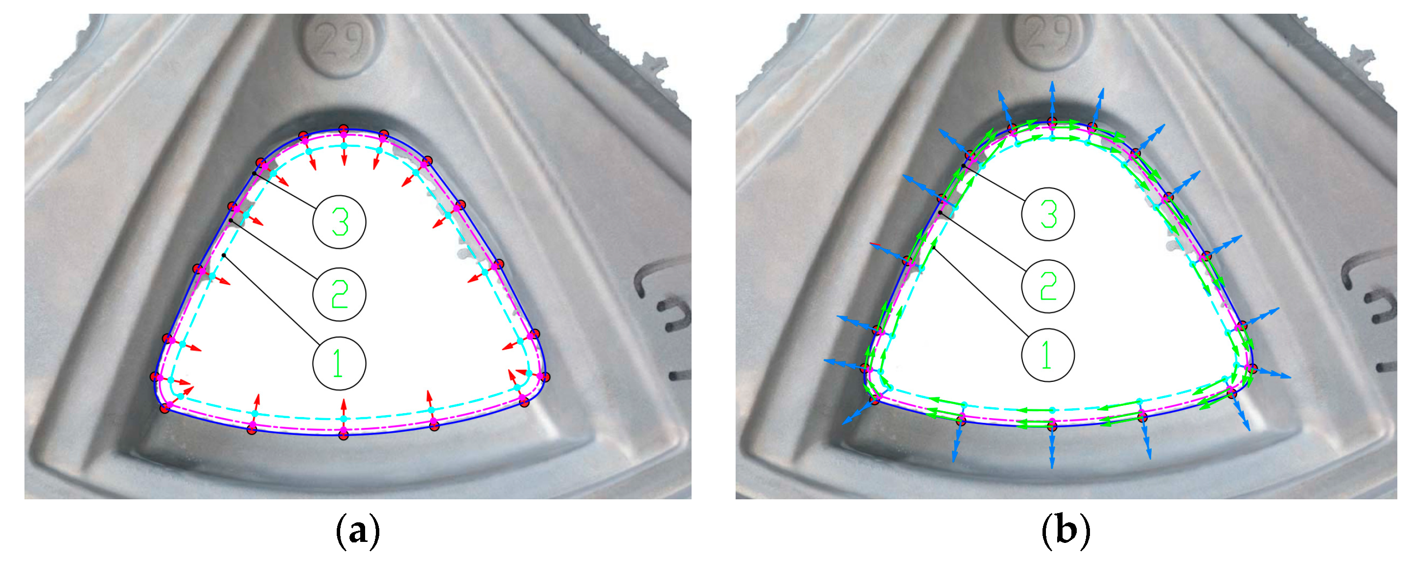
Furthermore, a total of eighteen discrete points were selected on the entire target curve at the edge of disc body, as shown in
Figure 13. The position of each contact point of the layered deburring tool is planned by the Equations (1) and (2) along the exterior normal
(red arrows are showed in
Figure 14a) of each discrete point, as shown in
Figure 14a. As mentioned above, disc burrs of the automobile hub were suitable for deburring with the tool side cutting edge and the contact orientations of the layered deburring tool were planned as shown in
Figure 14b. The details were: (a) the deburring direction of tool, i.e., the tool side edge vector
was taken as the unit inner normal vector
of each discrete position (i.e., cyan arrows, as shown in
Figure 14b, and they were in the opposite direction of the red arrows as shown in
Figure 14a); (b) the movement direction of tool (vector
) was planned along the unit tangent vectors
of each discrete position (i.e., green arrows, as shown in
Figure 14b) and points to the next discrete position to be deburred; and (c) the tool vector
was derived as
. Finally, the disc deburring of the automobile hub was conducted in the clockwise direction based on the planned tool contact positions and tool contact orientations as shown in
Figure 14 (symbols ①, ② and ③ represent the sequence of each layered deburring).
Additionally, the proposed robotic deburring process parameter control method was applied to the robotic deburring of the first experiment in order to adjust robotic deburring process parameters with a constant cutting speed and a constant cutting force. In this experiment, the robotic spindle speed was selected to be 10,000 rpm, and the line speed of the robotic feed was set to 30 mm/s. Hence, the desired robotic spindle speed and the desired robotic spindle load were 10,000 rpm and 0.17N·m. Variation ranges
,
,
and
(corresponding to
,
,
and
, respectively) were set to
,
,
and
, respectively. Variation ranges of output variables, i.e., change in control voltage of the robotic spindle and change in robotic feed (corresponding to
and
, respectively), were set to values such that
and
, respectively. From (3)–(8), quantizers of
,
,
and
, and scaling factors of
and
, were obtained as
,
,
, and
, and
and
, respectively. Furthermore, adjustment factors
and
were set to
and
, respectively. Hence, the fuzzy rules in the designed fuzzy controller for robotic spindle speed and robotic spindle load are expressed respectively as follows:
The experimental platform and the automobile hub workpiece of the first robotic experimental deburring are shown in
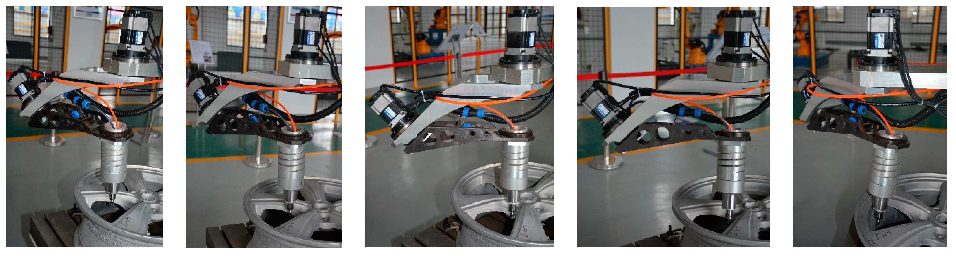
Figure 15. The detailed robotic experimental deburring for disc burrs of the automobile hub on the original experimental platform is shown in
Figure 16. Results of layered experimental deburring disc of the automobile hub workpiece are shown in
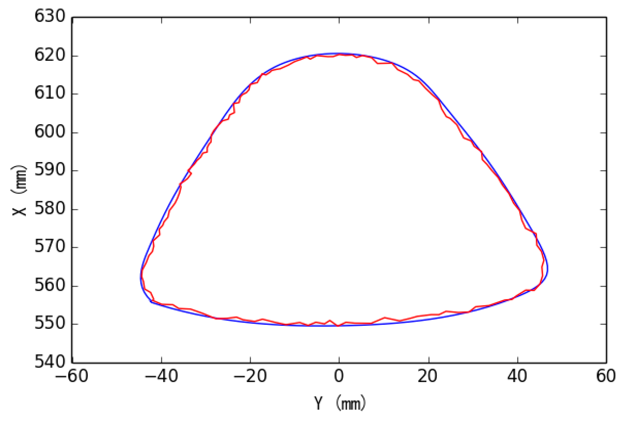
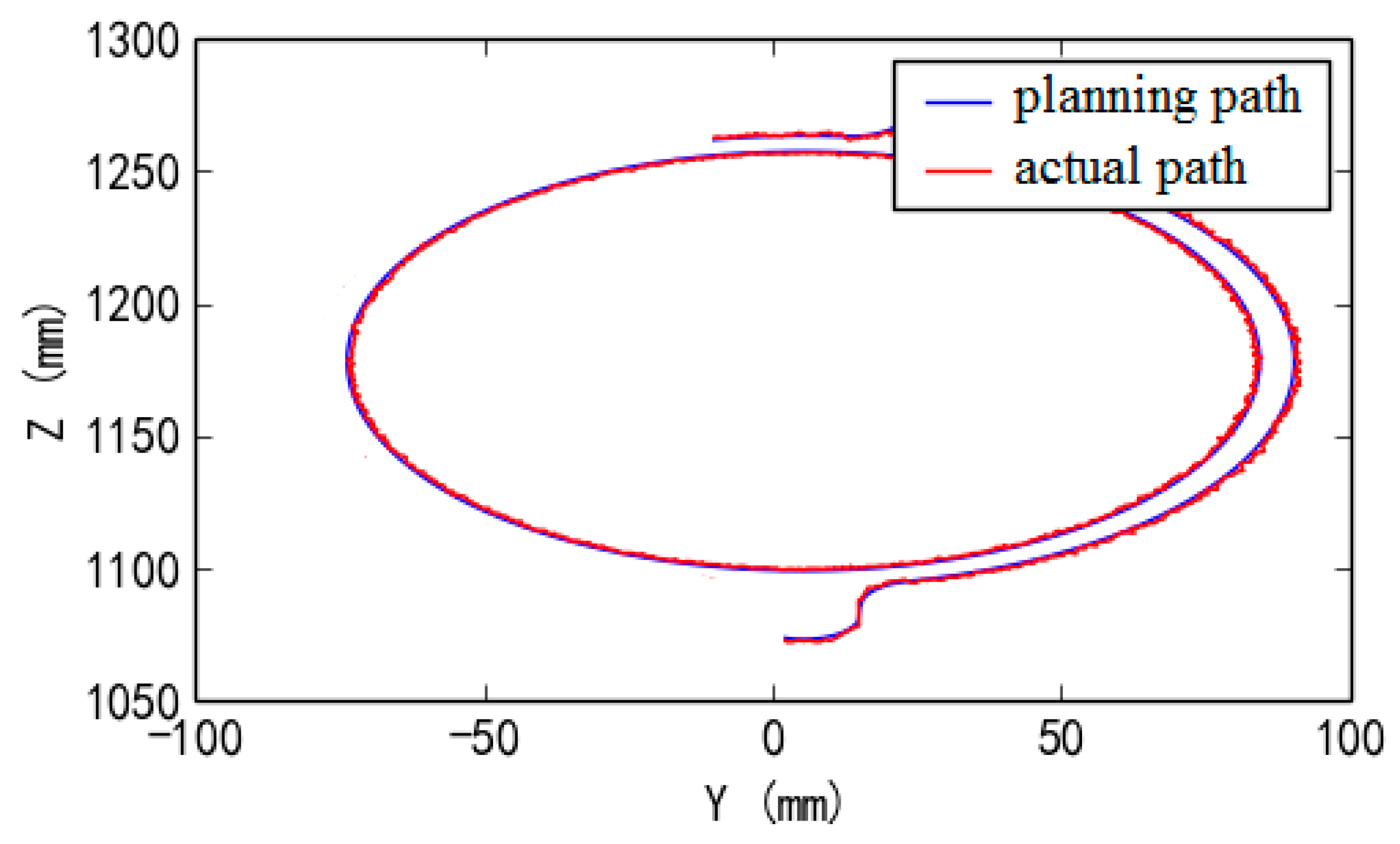
Figure 17. Finally, the results of the target planning path and actual tool path of experimental deburring for the automobile hub workpiece are shown in
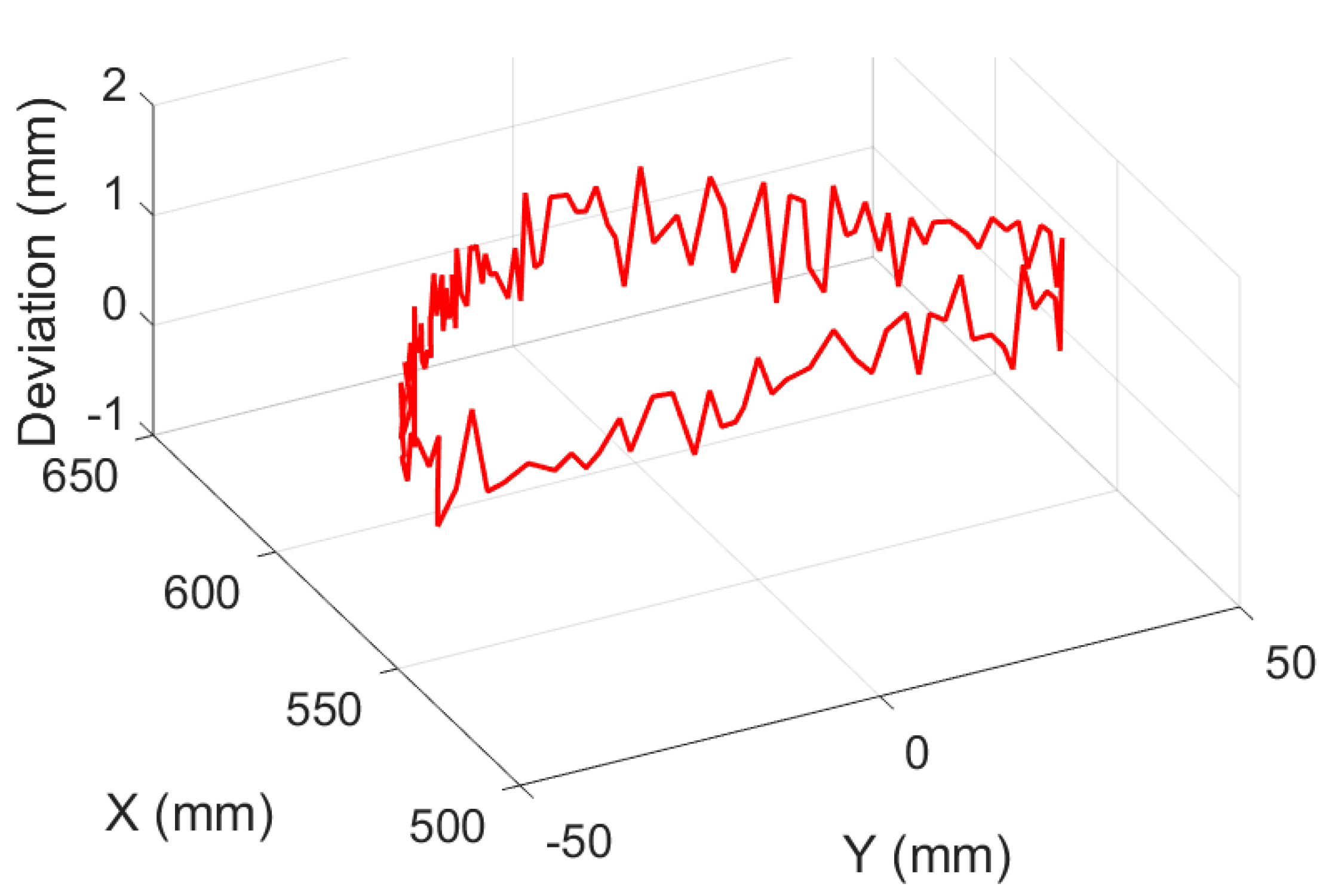
Figure 18 (here, the blue line and the red line are the target planning path and the actual tool path, respectively). Deviation results of target planning path and actual tool path of experimental deburring for disc of hub are shown in
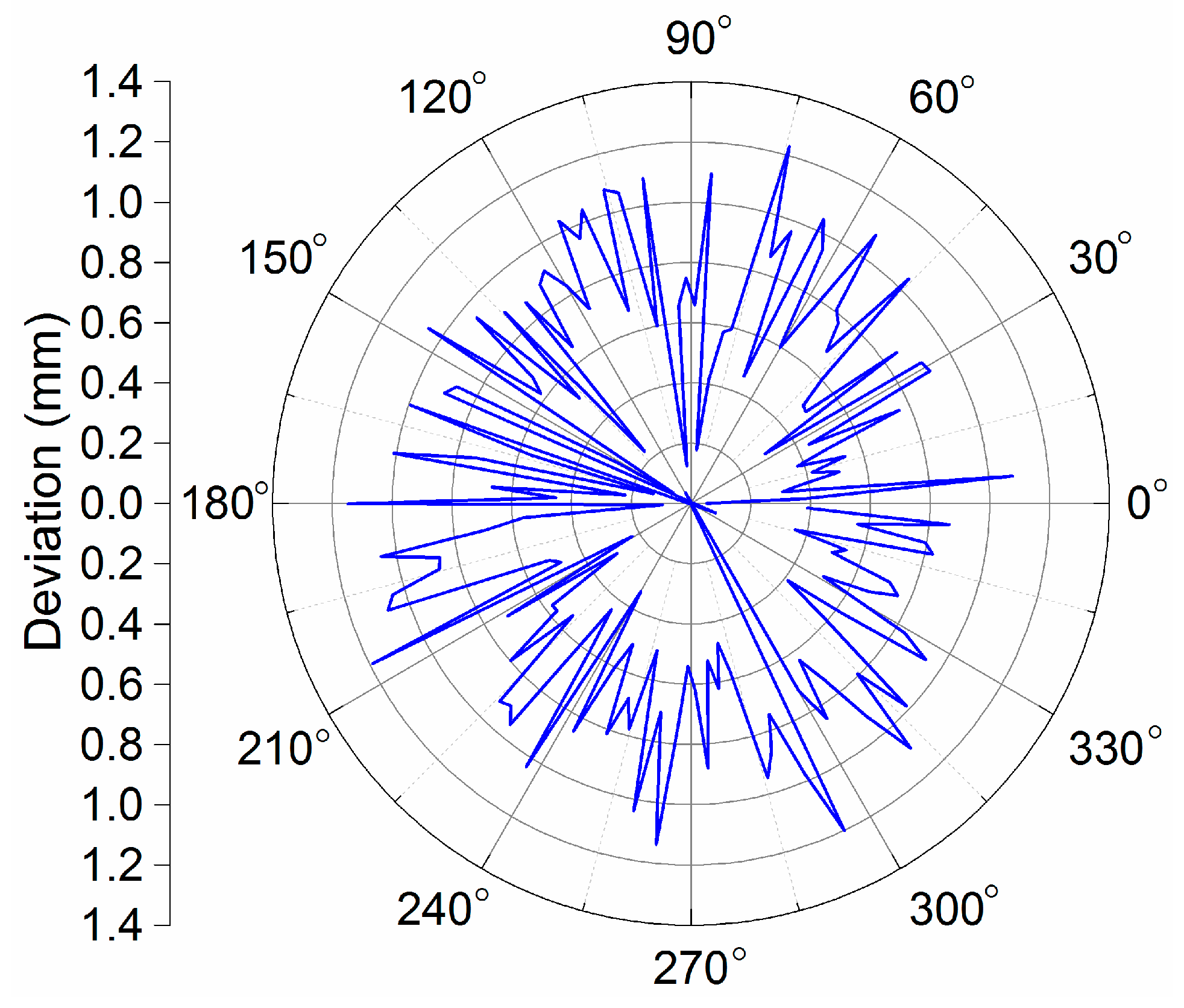
Figure 19, the vertical axis indicates the magnitude of the deviation, and other two horizontal axes in the horizontal plane indicate the corresponding positions of the target planning path in the deburring experiment. In addition, a figure in the form of plane polar coordinates illustrating deviation results of this experiment deburring is shown in
Figure 20. The maximum deviation was 1.23 mm, and these robotic deburring results can meet the experimental deburring requirements.
The effectiveness of the proposed robotic deburring tool path planning method and the proposed robotic deburring process parameter control method were verified in the first deburring experiment. Also, it can be seen that the robotic deburring orientations were adjusted dexterously, especially in the place where the local curvature changes greatly, and the dexterous deburring ability of the robot manipulator was fully demonstrated in the first deburring experiment.
6.2. Multifaceted Edges Robotic Deburring Experiment
In the second robotic deburring experiment, multifaceted edges deburring for an automobile steering booster housing were conducted on the improved experimental platform of the robot manipulator (shown in
Figure 2b and
Figure 8a). The experimental object was an aluminum alloy casting automobile steering booster housing (shown in
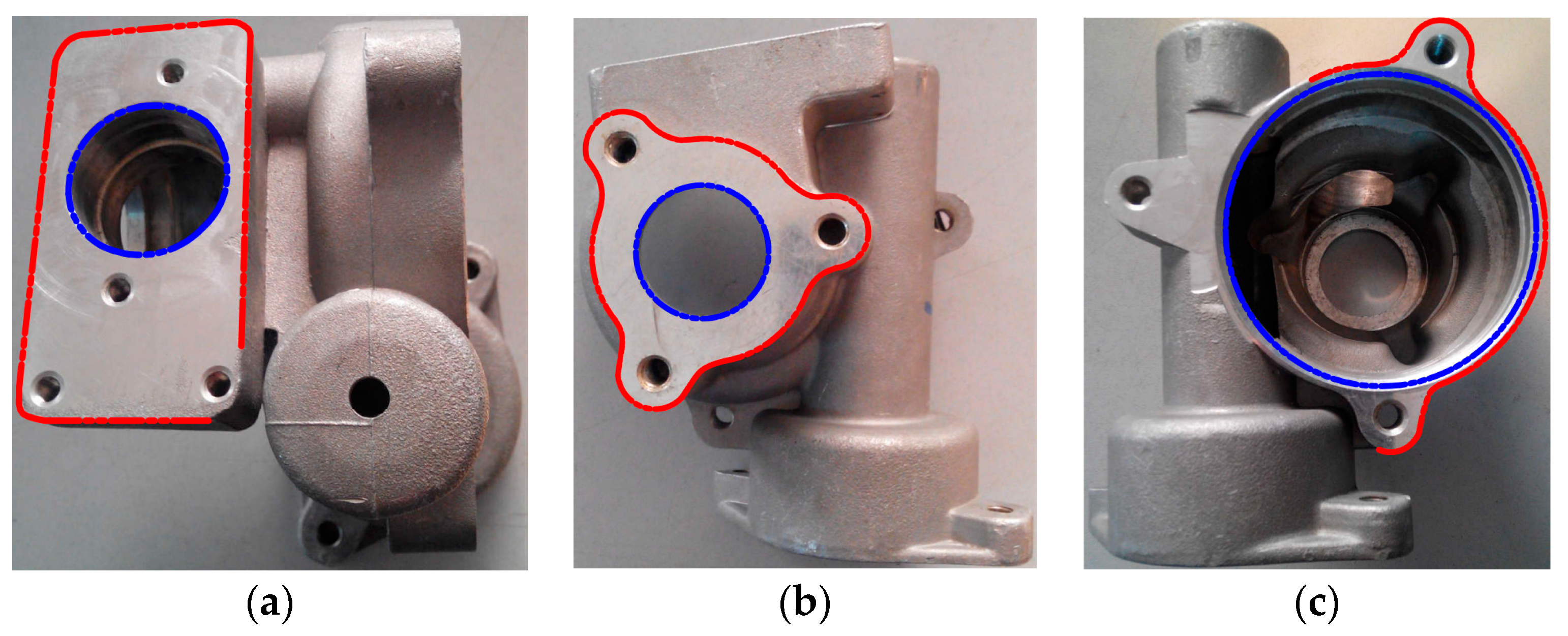
Figure 8b), and the experimental deburring object were multifaceted edges of the automobile steering booster housing, as shown in
Figure 21, i.e., orifice edges (blue lines are showed in
Figure 21) and facet edges (red lines are showed in
Figure 20) on top facet, distal side facet and proximal side facet relative to the initial position of the robot manipulator, as shown in
Figure 21a,b,c, respectively.
A double-cutting arch round-head carbide rotary tool with the side cutting edge (shown in
Figure 12c and its type—FX1020M06) was selected to conduct the deburring for multifaceted edges of automobile steering booster housing in the second experiment. In the multifaceted edges deburring experiment, the planned movement directions of the robotic deburring tool were clockwise and counterclockwise for orifice edges deburring and facet edges deburring, respectively.
Since burrs on multifaceted edges are very small, the entire allowance of each facet edge burrs could be deburred completely only once. Similarly, the proposed robotic deburring tool path planning method and the proposed robotic deburring process parameter control method were applied as in the first deburring experiment. Among them, the robotic spindle speeds for orifice edges deburring and facet edges deburring are selected to be 10,000 rpm and 8000 rpm, respectively; and the line speeds of the robotic feed for top facet edges deburring and other edges deburring were set to 30 mm/s and 20 mm/s, respectively. Note that these selected values for robotic spindle speeds and robotic feed speeds are not guaranteed to be very suitable as they are selected only according to limited past experiences. As mentioned above, the most appropriate way of selecting extremely suitable robotic deburring feed speed and tool spindle speed for specific deburring workpiece needs to refer to some related research issues for the technical details and be verified by a series of deburring experiments.
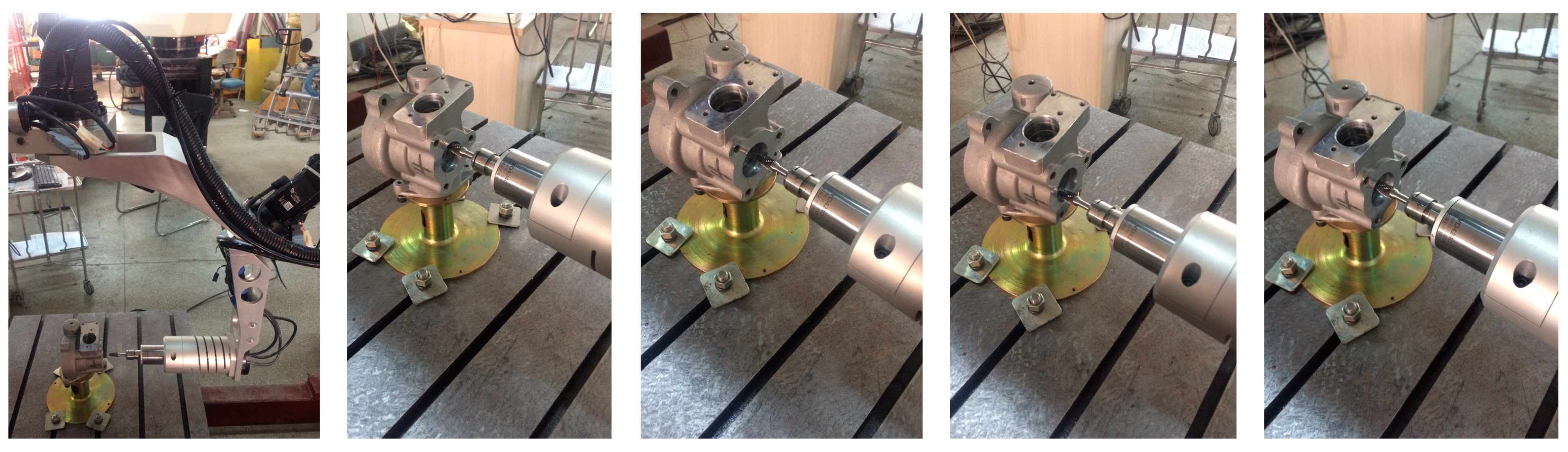
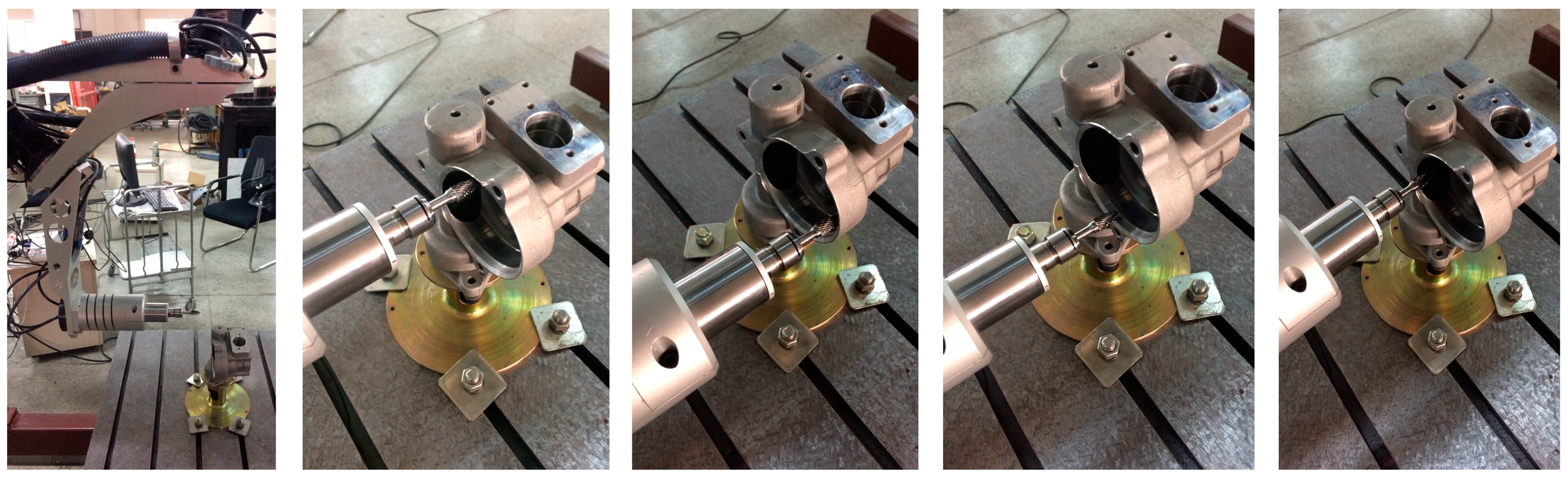
The detailed robotic experimental deburring for orifice edges and facet edges on the top facet, distal side facet and proximal side facet are shown in
Figure 22 and
Figure 23,
Figure 24 and
Figure 25, and
Figure 26 and
Figure 27, respectively. Finally, experimental deburring results for multifaceted edges of the automobile steering booster housing are shown in
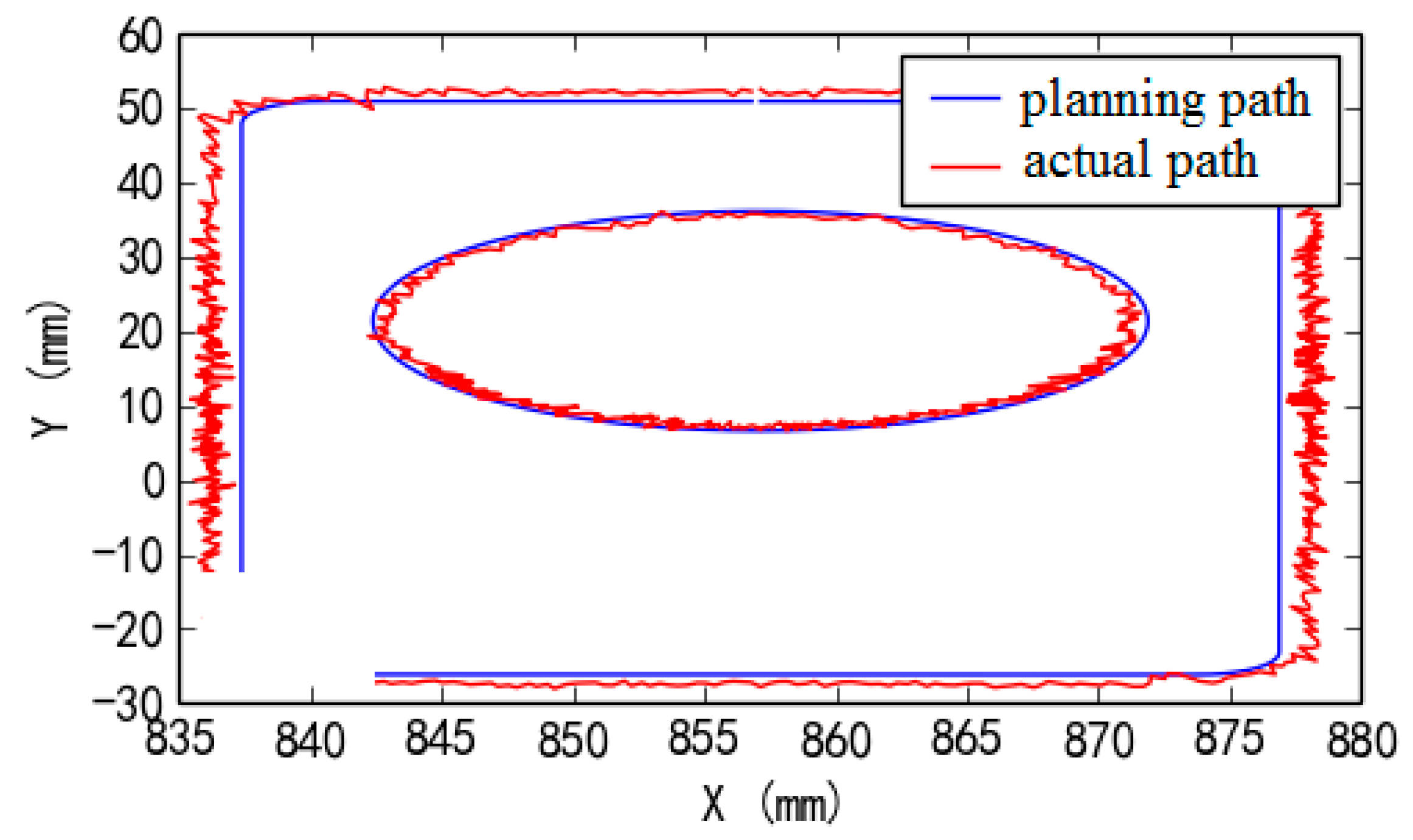
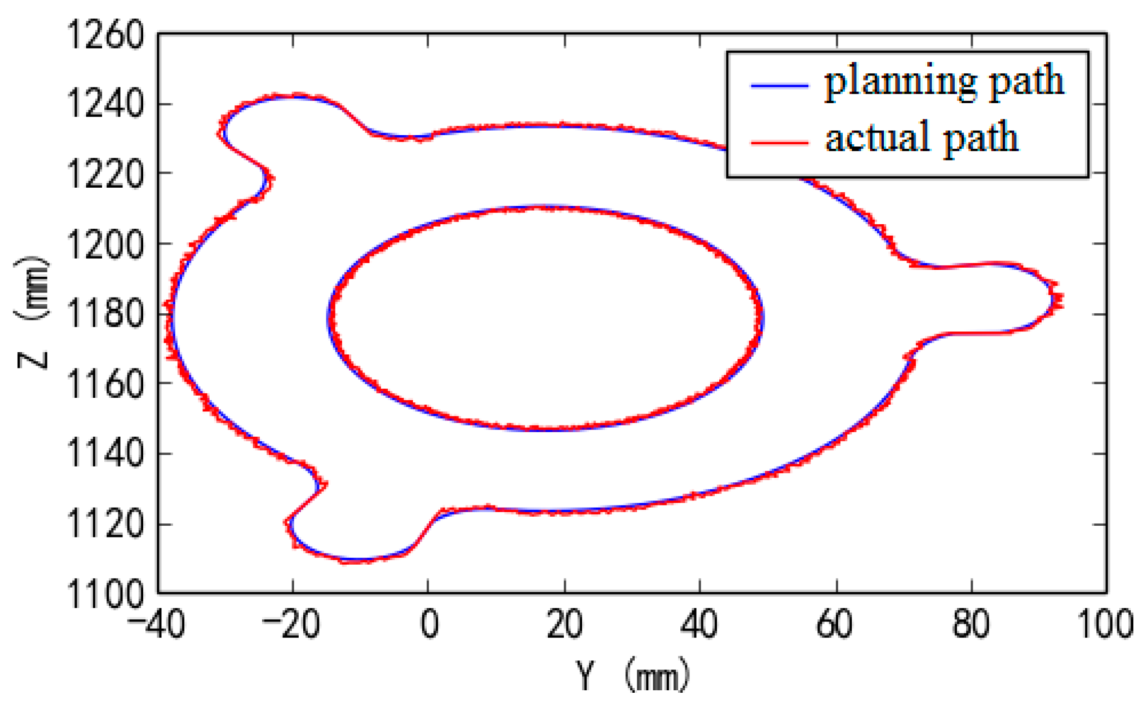
Figure 28. And robotic experimental deburring results of target planning path and actual tool path of top facet, distal side facet and proximal side facet are shown in
Figure 29,
Figure 30 and
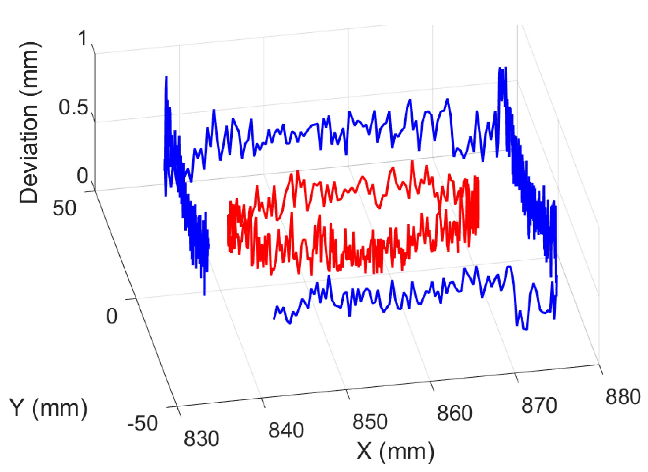
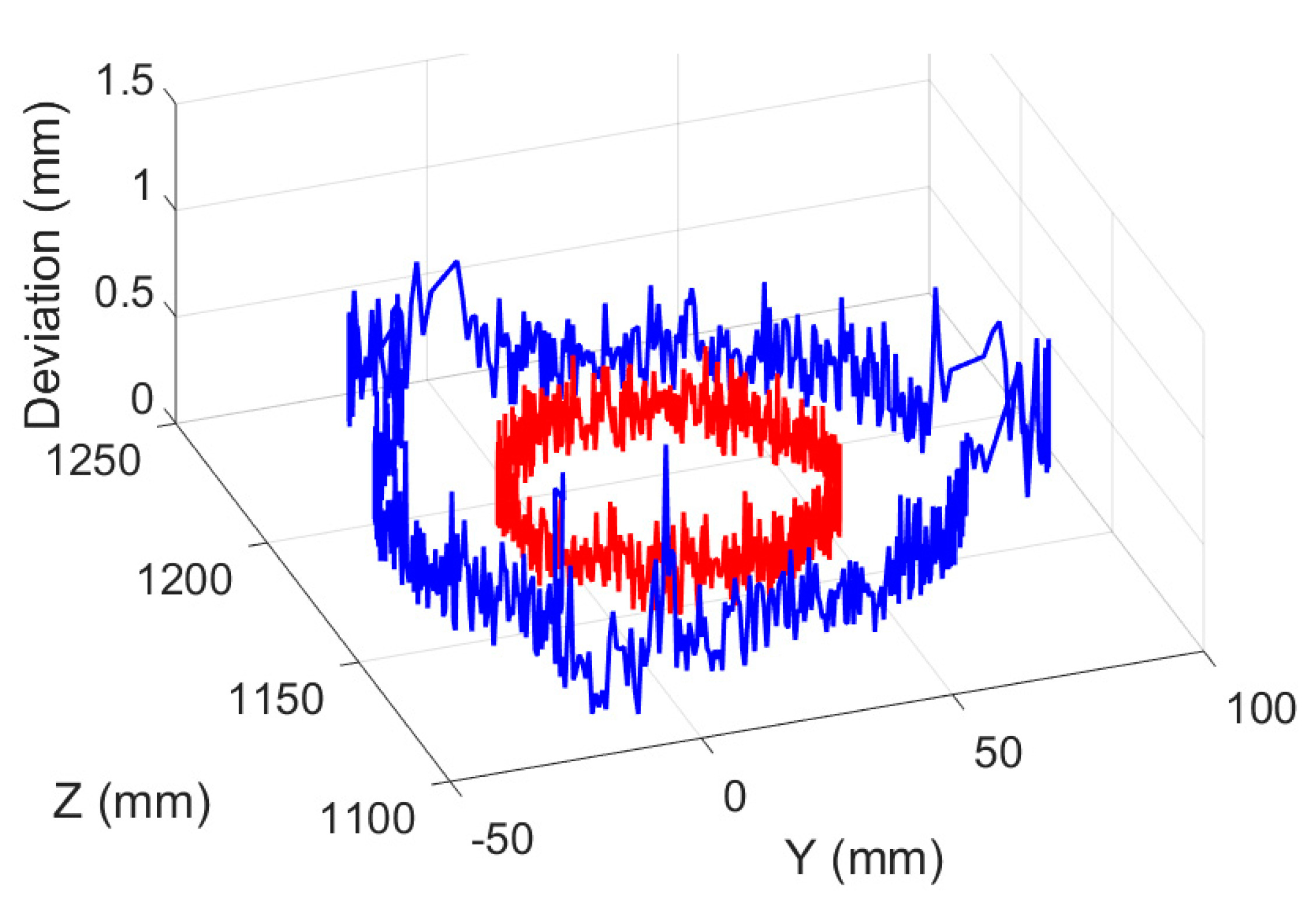
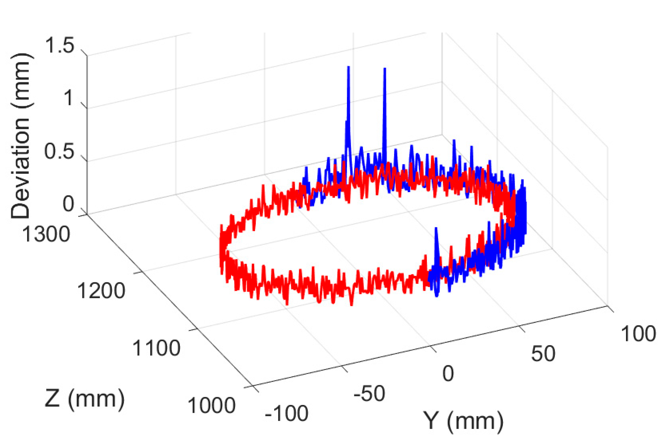
Figure 31, respectively (here, the blue line and the red line are the target planning path and the actual tool path, respectively). Deviation results of target planning path and actual tool path of robotic experimental deburring for top facet, distal side facet and proximal side facet are shown in
Figure 32,
Figure 33 and
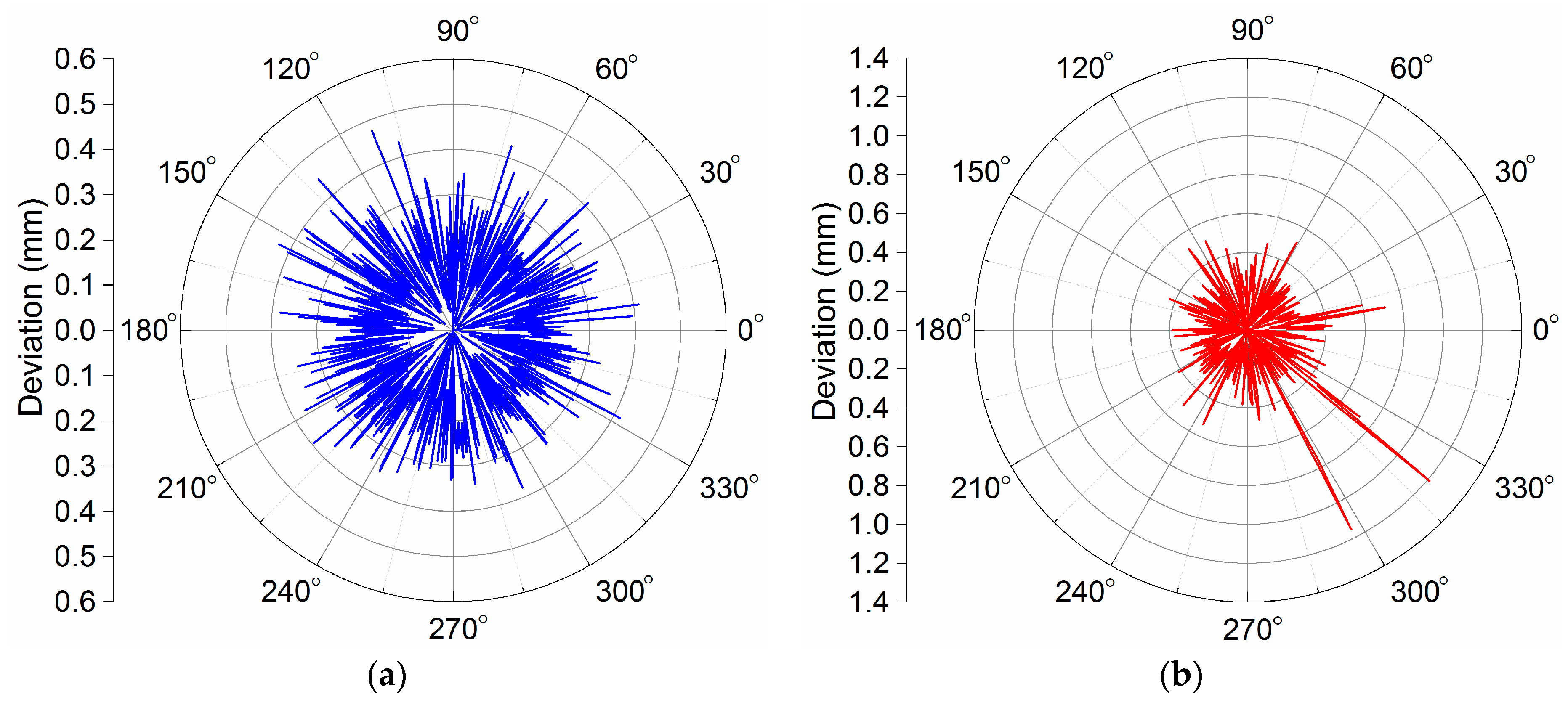
Figure 34, respectively. In each deviation figure, the vertical axis indicates the magnitude of the deviation, and other two horizontal axes in the horizontal plane indicated the corresponding positions of the target planning path in the deburring experiment (here, the blue line and the red line are the facet edges deburring deviation results and the orifice edges deburring deviation results, respectively). In addition, three figures in the form of plane polar coordinates illustrating deviation results of this experiment deburring for top facet, distal side facet and proximal side facet are shown in
Figure 35,
Figure 36 and
Figure 37, respectively. Among them, the maximum path deviations of top facet edge, distal side facet edge and proximal side facet edge were 0.97 mm, 1.13 mm and 1.21 mm, respectively. These robotic deburring results can satisfy the experimental deburring requirements.
It can be showed that the effectiveness of the proposed robotic deburring tool path planning method and the proposed robotic deburring process parameter control method were also verified in the second deburring experiment. Furthermore, the highly efficient and dexterous manipulation and deburring capacity of the robot manipulator for multifaceted deburring in one setup was totally demonstrated in the second deburring experiment. In addition, it should be noted that the proposed methods can be now only applied to soft material machining applications and low machining requirements due to the rigidity defect of the robot manipulator and lacking compensation for vibrations and/or chattering, although it had a very high level of dexterous manipulation and orientation reachability. There are still many meaningful research issues need to be conducted in the next step in order to improve the path accuracy of the robot manipulator, such as offline path correction, compensation for vibrations and/or chattering, high frequency oscillation suppression, structural rigidity improvement, calibration of the robot manipulator for dealing with nonnegligible dynamic effects which are caused by backlash of ball screws and robot manipulator structural deformations.
It is necessary to note that, when the end-effector tool of the robot manipulator is changed, like an abrasive belt or a fabric wheel, the robot manipulator can also conduct deburring, grinding and polishing for edges and surfaces of castings or other materials, such as parting line burrs, flash burrs, pouring risers burrs, and so forth.


