Article

A Hierarchical Mission Planning Method for Simultaneous Arrival of Multi-UAV Coalition

1
National Key Laboratory of Special and Technology on UAV, Northwestern Polytechnical University, Xi’an 710065, China
2
School of Astronautics, Northwestern Polytechnical University, Xi’an 710072, China
3
UAV Research Institute, Northwestern Polytechnical University, Xi’an 710065, China
4
School of Aeronautics, Northwestern Polytechnical University, Xi’an 710072, China
*
Author to whom correspondence should be addressed.
Appl. Sci. 2019, 9(10), 1986; https://doi.org/10.3390/app9101986
Submission received: 31 March 2019 / Revised: 11 May 2019 / Accepted: 13 May 2019 / Published: 15 May 2019
(This article belongs to the Special Issue Unmanned Aerial Vehicles (UAVs))

Abstract

:

Featured Application

Cooperative task allocation and path planning problems of multi-UAV are becoming more and more important. The proposed mission planning method can be easily applied to some civilian scenarios, such as multi-UAV cooperative forest fire fighting and some military scenarios.

Abstract

A hierarchical mission planning method was proposed to solve a simultaneous attack mission planning problem for multi-unmanned aerial vehicles (UAVs). The method consisted of three phases aiming to decouple and solve the mission planning problem. In the first phase, the Pythagorean hodograph (PH) curve was used in the path estimation process for each UAV, which also served as the input for the task allocation process. In the second phase, a task allocation algorithm based on a negotiation mechanism was proposed to assign the targets. Considering the resource requirement, time-dependent value of targets and resource consumption of UAVs, the proposed task allocation algorithm can generate a feasible allocation strategy and get the maximum system utility. In the last phase, a path planning method was proposed to generate a simultaneous arrival PH path for each UAV considering UAV’s kinematic constraint and collision avoidance with obstacles. The comparison simulations showed that the path estimation process using the PH curve and the proposed task allocation algorithm improved the system utility, and the hierarchical mission planning method has potential in a real mission.

1. Introduction

Over the last decades, unmanned aerial vehicles (UAVs) have been widely used in a large range of applications, such as environmental monitoring [1], searching and attacking [2], forest fire fighting [3] and so on. Due to the capability limitation of a single UAV, multiple UAVs working together in coordination are expected to perform more complex missions under various types of attack [4]. For example, multiple UAVs can accomplish an attack mission much better than a single UAV when those UAVs arrive simultaneously to the target.
Two main aspects in multi-UAV attack mission are task allocation and path planning. The complexity of these problems increases with the number of UAVs and tasks. In addition, in some specific scenarios, the imposed constraints, such as resource requirement, collision avoidance and simultaneous arrival constraints further increase the complexity of those problems.
Many researchers treated the task allocation and path planning as two sub-problems separately in the in multi-UAV attack mission, they use a centralized or distributed approach to obtain a feasible task allocation strategy and then use path planning algorithms to generate feasible paths for UAVs. Sharma et al. [5] proposed a cooperative ad-hoc network framework for multi-UAV using a neural network, cooperative task allocation and path planning algorithms can be used in the framework in different applications. Yao et al. [6] developed an iterative mission planning framework for the task allocation and path planning problems, an improved auction algorithm with an iterative strategy was proposed in the task allocation process. When multi-UAV is used to perform multi-task, the task allocation and path planning process are coupled [7], as the performance of task allocation depends on an accurate path length of UAVs, and the path planning depends on the UAV’s task allocation results.
To solve the coupled task allocation and path planning problems, there are two main ways. In the first class of methods, Euclidean distance between UAVs and targets is seen as the input in the task allocation process [8,9]. After obtaining the feasible allocation results, the path planning process is used to generate flyable and safe paths/trajectories for UAVs considering a variety of constraints. However, the length of the generated paths/trajectories are quite different from the Euclidean distance, especially when there are obstacles in the environment. This deviation will result in poor quality of solutions obtained in the task allocation process. The second method considers the task allocation and path planning process as an integrated optimization problem, and encoding the solution of the coupled problem, genetic-based [10,11] and decision tree [12] algorithms are usually used. However, simultaneously solving task allocation and path planning needs a large amount of computation.
The presented task allocation studies above assume each target can be performed by single UAV and the resources of UAVs do not deplete. However, in a real situation, some targets may need a variety of resources and should be performed by multi-UAV simultaneously, such as for a simultaneous attacking mission, multiple UAVs are required to reach the target simultaneously with a different entry angle to maximize the mission performance. This problem can be called the single-task, multi-robot (ST-MR) problem according to the taxonomy criteria proposed by Gerkey et al. [13]. The ST-MR problem is also known as the coalition formation problem [14], a coalition means a team of UAVs performing the same target.
To solve the coalition formation problem for multiple UAVs performing multi-target, two distributed sub-optimal coalition formation algorithms were proposed to form coalition with minimum time and size to destroy targets simultaneously [15,16]. In a search and destroy mission for multiple UAVs, a welfare-based coalition formation algorithm for heterogeneous UAVs was presented by Kim et al. [17], the UAVs use resources in a balanced manner to improve the system’s robustness in the dynamic and uncertain environment. However, the works cited above assume that only the UAV performing a search task can send a bid to form a coalition, they do not consider the overlapping coalitions, which will decrease the mission performance. For the cooperative task allocation and rendezvous problems, Sharma et al. [18] proposed a global optimization algorithm inspired by the biological features of the hill Myna and desert Sparrow, the algorithm can be applied to ad-hoc networks in various applications. For the overlapping coalitions problem, Oh et al. [19] proposed two distributed coalition formation algorithms for multi-UAV based on the contract net protocol, the sequence of UAVs and pop-up tasks are considered in the dynamic environment with limited communication range. The studies cited above do not take into account the obstacles and no-fly-zones in the environment, which significantly limits the application of the coupled task allocation and path planning algorithm.
To maximize the system performance, the paths for the UAVs in the same coalition should satisfy simultaneous arrival as well as some other constraints, such as the kinematic constraint of a UAV and collision avoidance with obstacles. For the simultaneous arrival problem (also called rendezvous problem), the velocity-based [20,21] method has been used. The simultaneous arrival problem of multiple UAVs is addressed by a velocity control approach [20], the UAVs communicate with each other to make a consensus on the estimated time of arrival. A distributed optimization algorithm based on game theory [21] was proposed for a UAV rendezvous problem, each UAV adjusts its velocity according to the states of its neighbors in a predefined time interval. However, this method is easy to cause velocity saturation [22] and a large amount of communication is required. Some other studies [7,23] assume all the UAVs fly at the same and constant speed, so the simultaneous arrival for multi-UAV can be achieved by planning paths of equal length. In our previous work, a cooperative particle swarm optimization (CPSO) algorithm is proposed to generate Pythagorean hodograph (PH) paths of equal length for each UAV. However, the task sequence of UAVs is not considered.
In this paper, the focus is on the coupled task allocation and path planning problems for multi-UAV performing simultaneous arrival tasks. Considering the target’s resource requirement, simultaneous arrival, time-dependent values of targets, resource consumption of UAVs and collision avoidance with obstacles. A hierarchical mission planning method is proposed to solve the coupled task allocation and path planning problem for a multi-UAV performing a multi-task, which is also the contribution of this paper. The method consists of three phases. In the first phase, the PH curve is calculated as the estimated path for each UAV, which can provide a more accurate input for the task allocation process. Then, a task allocation algorithm is proposed to form a coalition for each target considering the task sequence of UAVs and the resource requirement of targets. Finally, the path planning process generates the flyable and safe paths for the fixed-wing UAVs in the same coalition to realize the simultaneous arrival.
The rest of this paper is organized as follows: In Section 2, a description of the multi-UAV cooperative attacking problem is given. Section 3 describe the task allocation method for multi-UAV. In Section 4, path planning method to achieve simultaneous arrival is presented. Experimental results are shown in Section 5. In Section 6, the conclusions are given.

2. Description of the Multi-UAV Cooperative Attack Problem

The problem considered in this study consists of assigning a fleet of heterogeneous UAVs to a set of targets. At the initial time, there are some targets in the environment, it is assumed the information of these targets are known at the initial time. The UAVs are required to attack the targets.
In this paper, the UAVs and targets are modeled based on their resources. Each target may need a coalition of UAVs. According to the information of the targets and UAVs, the appropriate UAVs are allocated to each target. In order to maximize the system performance, the UAVs performing the same target are required to arrive to the target simultaneously. Then, the path planning process is used to generate simultaneous arrival paths for the UAVs in the same coalition. The resource requirement and simultaneous arrival of targets, the UAV’s kinematic constraints and collision avoidance with obstacles are taken into account.
In this study, some assumptions were made to simplify the problem:
  • For simplicity, the take-off and landing process of UAVs were not taken into account, the collision avoidance among UAVs were achieved by altitude layering.
  • In the task allocation process, the communication topology remained unchanged.
  • The aerodynamic and attitude of UAVs were not considered.
  • The obstacles and targets considered in this paper were static.

2.1. Targets and UAVs

Let T = { T 1 , T 2 , , T M } be the set of M stationary targets, it is assumed that the information of targets is known at the initial time. Each target requires m-different types of resources, the resource requirement of target T j can be expressed as Equation (1), for example, R T j = ( 3 , 3 , 2 ) denotes that there are three types of resources required to destroy target T j and the required amount of each resource is 3, 3 and 2, respectively.
R T j = ( R 1 T j , R 2 T j , , R m T j ) ,   j = 1 , , M
Let V a l u e = ( V a l u e 1 , , V a l u e M ) be the set of values of the targets at the initial time, the value of targets decreases with time as follows:
r e w a r d j = V a l u e j e β t j
where β > 0 is a user-defined coefficient, which denotes the descent rate of the target’s value. t j is the time of arrival of the UAV coalition assigned to attack the target T j .
Let U = ( U 1 , U 2 , , U N ) be the set of N heterogeneous UAVs. The heterogeneity of UAVs is reflected in their different dynamic characteristics and the amount of resources as shown below:
R U i = ( R 1 U i , R 2 U i , , R m U i ) ,   i = 1 , , N
It is assumed that all UAVs fly in a two-dimensional plane. The motion of UAV U i is governed by the following equation:
[ x ˙ i y ˙ i φ ˙ i ] = [ cos φ i 0 sin φ i 0 0 1 ] [ V i ω i ]
where ( x i , y i ) and φ i represents the Cartesian coordinates and the heading angle of UAV U i , respectively. V i and ω i denote the velocity and turn rate, respectively. It is assumed that the UAVs fly at a constant and same velocity.
The control input for each UAV can be described as: u i ( t ) = ω i ( t ) , which is subject to the constraints in Equation (5). R min i is the minimum turning radius of UAV U i .
ω i | V i / R min i |
In this paper, the UAVs were required to perform the attacking mission to the targets. The objective of the mission planning problem is to obtain the assignment strategy for each UAV to maximize the objective function and provide flyable and safe paths for these UAVs.

2.2. Objective Function and Constraints

The objective of the task allocation problem is to assign the targets to the UAV team to obtain the maximum system utility. To satisfy the resource requirement of targets, there may be some UAVs forming a coalition to attack one target. The reward to destroy targets and the cost of the UAV coalitions were considered in the objective function, so, two criteria were selected to quantify the objective function of this mission planning problem: The reward to destroy targets and the cumulative path length of all the UAV coalitions. Thus, the objective function to be maximized is as follows:
J = j = 1 M ( w 1 × V a l u e j × e β t j w 2 × i = 1 | C j | L i j )
where w 1 , w 2 respectively denotes the weights of the reward and cost. C j represents the UAV coalition assigned to attack the target T j , | C j | denotes the number of UAVs in the coalition C j , L i j denotes the path length from the initial location of UAV U i to the target T j . Assuming A ( i ) is the task sequence of UAV U i , tasks before T j should be considered in calculating L i j . t j is the estimated time of arrival (ETA) of the latest UAV in the coalition assigned to the target T j :
t j = max i C j ( E T A ( i , j ) )
The constraints considered in this paper can be categorized into UAV-related constraints, target-related constraints and environment-related constraints.
(1) UAV-related constraints
First of all, UAVs have limited fuel, so a maximum flying distance constraint should be satisfied:
L ( A ( i ) ) L max i ,   i = 1 , , N
where L ( A ( i ) ) is the total path length of UAV U i , L max i denotes the maximum flight distance of UAV U i .
Each UAV can carry limited resources that deplete with use, so each UAV cannot consume more resources than it carries.
R ( A ( i ) ) R U i
where R ( A ( i ) ) represents the total resource consumption for performing the targets assigned to U i .
A flyable curve [24] is required to satisfy the UAV’s kinematic constraint. In a two-dimensional plane, a curve is determined by its curvature. Let κ i ( q ) be the curvature of UAV U i at point q , the curvature of the path should be continuous and bounded as follows:
κ i ( q ) 1 / R min i
(2) Target-related constraints
Each target is required to be performed by a UAV coalition simultaneously, and the resource requirement should be satisfied:
( U C j R p U ) R p T j ,   p = 1 , , m ;   j = 1 , M
(3) Environment-related constraints
Let Ω be the two-dimensional space in which UAVs fly. Let Θ denote the set of obstacles in the environment. The collision avoidance between UAVs and obstacles must be satisfied:
( x ( t ) , y ( t ) ) int ( Θ ) =
(4) Simultaneous arrival constraints
According to the resource model, each target may need a coalition of UAVs. To maximize the system performance, the UAVs in the same coalition are required to arrive to the target simultaneously as follows:
t i , j p a t h = t l , j p a t h ,   i , l { 1 , , | C j | } ; i l
where U i and U l are two different UAVs in coalition C j , T j is the target assigned to the coalition C j .
Thus, the mission planning problem was provided as the objective function (Equation (6)) with constraints (Equations (8)–(13))

3. Task Allocation

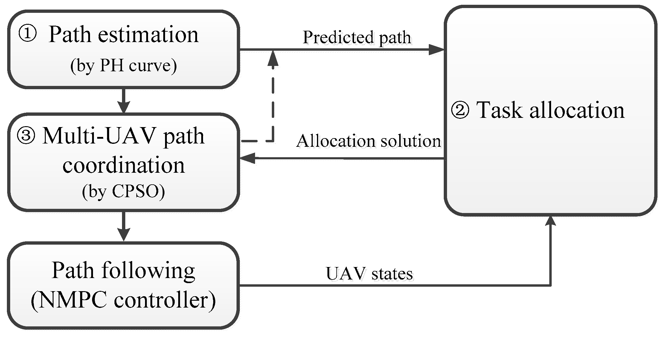
3.1. Framework of the Mission Planning Method

Inspired by the hierarchical control framework [25,26,27] of a multi-UAV system. The mission planning method was divided into three layers in this paper, as shown in Figure 1. The first layer was the path estimation process, a Particle Swarm Optimization-based method (shown in Section 4.2) was employed to generate a PH path for each UAV as an estimated path. The length of the estimated path was seen as the input for the task allocation process, the estimated path was used to decouple the task allocation and path planning problems. In the second layer, the task allocation process assigned targets to UAVs that optimized the system performance. A task allocation algorithm was proposed to assign the targets. In the task allocation process, the resource requirement of targets, resource consumption and task sequence of UAVs were taken into account. In the last layer, according to the task allocation strategy, a path planning method was proposed to generate flyable and safe paths for the UAVs considering the task sequence of each UAV. In this layer, the simultaneous arrival, UAV’s kinematic and collision avoidance constraints were considered (detailed explanation can be found in Section 4.3). Finally, a path following process was used to generate the control signals for the UAV team. As the path following was not the focus of this paper, a path following method based on the nonlinear model predictive control [28] (NMPC) was used to track the generated PH paths.

3.2. Task Allocation Algorithm

The task allocation process defined in Section 2.2 is a Non-deterministic Polynomial hard problem. With the increasing size of the problem, the computational complexity will be increased sharply. It will be time-consuming and even impossible to obtain the optimal solution. In order to obtain a feasible solution within a reasonable time, in this paper, the task allocation algorithm assigns the most profitable target in each allocation round. In each allocation round, each UAV selects the most beneficial target to itself. Then, if there is a conflict among different UAVs, a consensus mechanism is used. The resource requirement of targets and task sequence of UAVs were considered. As mentioned above, the task allocation and path planning were coupled. In this paper, the path estimation process using the PH curve was used to decouple these two problems. The proposed task allocation algorithm based on a negotiation mechanism is presented as Algorithm 1.
Algorithm 1. Task allocation algorithm
Input: T : The set of targets and initial states; R T j , j = 1 , , M : Resource requirement of targets; U : The set of UAVs and initial states; R U i , i = 1 , , N : Resources of UAVs;
Output: A : The allocation matrix of the UAV team
1: for k = 1 : M do
2:  for U i , i = 1 , , N do
3:   for j = 1 to the number of unallocated targets
4:    calculate estimated reward for U i performing target T j
5:   end for
6:   select the pre-allocated target for U i
7:  end for
8:  consensus on pre-allocated target in this allocation round and select the manger UAV
9:  C j coalition_formation ( U j P , V a j , R T j )    ---Algorithm 2
10:  the UAVs in the coalition C j add the target T j into their task sequence
11:  calculate resource consumption for UAVs in the coalition C j
12:  cooperative path planning for simultaneous arrival to target T j    ---Section 4
13: end for
There were M targets at the initial time, each allocation round would assign one target (Line 1, Algorithm 1). Then, the estimated reward to perform all unallocated targets was calculated for each UAV using Equation (14; Line 4, Algorithm 1). Considering the task sequence of a UAV, the ETA of the UAV U i to the target T j can be represented as Equation (15).
R e w a r d ( i , j ) = V a l u e j × e β E T A ( i , j )
E T A ( i , j ) = { L i j e / V i , i f   A ( i ) = L i m b e f o r e / V i + L m j e / V i , o t h e r w i s e
where A ( i ) is the task sequence of the UAV U i , if A ( i ) = , which denotes there is no target assigned to the UAV U i , then L i j e is the estimated path length between the current location of the UAV U i to target T j , which can be obtained in the path estimation process (Section 4.2). Otherwise, there has been some targets assigned to the UAV U i , these assigned targets should be considered in calculating the E T A ( i , j ) . Assuming the last target in the task sequence of UAV U i is the target T m , the ETA from UAV U i to the target T j can be divided into two parts. The first part is the accurate path length of the assigned targets L i m b e f o r e , which can be obtained by the path planning process (Section 4.3) in the previous allocation round; the second part L i j e is the estimated path length from the target T m to T j , which can be obtained in the path estimation process.
Then, the UAV U i selects the most appropriate target j * as its pre-allocated target (Line 6 Algorithm 1):
j i * = arg max ( R e w a r d ( i , j ) ) j M
where M represents the targets, which have not been assigned.
After all the UAVs have computed their pre-allocated targets, there may be conflicts among UAVs. For example, more than one UAV selects the same target as their pre-allocated target. Here, a consensus algorithm [19] is employed for conflict resolution (Line 8, Algorithm 1). Each UAV achieves a consensus on the pre-allocated target by negotiating with others. The UAV with the highest estimated reward is seen as the manager UAV i m a n a g e r using Equation (17), the corresponding pre-allocated target of the manager UAV is regarded as the target to be allocated in this allocation round.
i m a n a g e r = arg max ( R e w a r d ( i , j i * ) ) i N
After the consensus process, every UAV knows the manger and the target to be allocated in this allocation round. Other UAVs, who have the required resource for the target are seen as the potential coalition members and will send applications to the manager UAV, the applications include their remaining resources and ETA. Then, the manager UAV uses algorithm 2 to determine the UAV coalition C j to perform the target to be assigned in this allocation round (for simplicity, expressed as T j in the following algorithm). Then, the UAVs in the coalition C j will augment the target into their task sequence (Line 10, Algorithm 1).
Algorithm 2. Select the coalition C j to perform target T j
Input: Potential coalition members U j P , number of potential coalition member n , resource requirement R T j of the target T j , initial value of target V a l u e j .
Output: The coalition C j to perform the target T j
1: for k = 1 : n do
2:  calculate all the potential coalitions of size k
3:  for m = 1 to the number of potential coalitions do
4:   R ( m ) = total resources of the potential coalition m
5:   if R ( m ) R T j
6:    C f e a s i b l e append the potential coalition
7:   end if
8:  end for
9:  if isempty ( C f e a s i b l e )
10:   continue
11:  else
12:   select the coalition C j which have the highest utility to perform target T j
13:  end if
14: end for
The manager UAV and the applicants were regarded as the potential coalition members for the target T j , they would form a list U j P . The coalition formation algorithm begins with finding all the feasible coalitions with sufficient resources and the minimum size (line 1–8, Algorithm 2). Then, the manager UAV selects the most appropriate coalition C j among all the feasible coalitions using Equation (18; Line 12, Algorithm 2). The utility for each coalition c C f e a s i b l e is calculated using Equation (6).
C j = arg max ( u t i l i t y ( c ) ) c C f e a s i b l e
Once the coalition C j is determined to perform the target T j , the coalition members will calculate the resource consumption that satisfying the target’s resource requirement (Line 11, Algorithm 1). A greedy resource management method was used in this paper. Assuming the type-p resource requirement of target T j is R p T j . The type-p resource consumption R p U k ( cost ) of UAV U k in the coalition C j can be represented as:
R p U k ( cost ) = { 0 , i f   i U b _ k R p U i R p T j min ( R p T j i U b _ k R p U i ) , o t h e r w i s e
where U b _ k represents the UAVs before U k , when elements in C j are arranged in descending order of reward.
After the calculation of resource consumption, the UAVs in the coalition C j update their remaining resources. Then, the simultaneous arrival paths for the UAVs in the coalition C j are generated by the path planning process (Section 4.3).

3.3. Complexity Analysis of the Task Allocation Algorithm

Given the information of the operating environment and configurations, the proposed task allocation algorithm can provide solutions at low complexity. Assuming there are N UAVs and M targets in the environment. In Algorithm 1, each allocation round will assign one target, it requires M allocation rounds to allocate all the targets. In each allocation round, step 2 in Algorithm 1 requires N iterations. For step 3–5 in Algorithm 1, they undergo M iterations for the worst case. The complexity for the consensus process [19] in Algorithm 1, step 8 is ( N 1 ) 2 for the worst case. In Algorithm 2, at most N elements are sorted, the complexity of the Algorithm 2 is N log ( N ) . Summing up the numbers analyzed above in each allocation round, the complexity of the proposed task allocation algorithm in the worst case can be computed as N M + ( N 1 ) 2 + N log ( N ) . For M targets (line 1 in Algorithm 1), the complexity of the proposed task allocation algorithm in the worst case can be expressed as M 2 N + M ( N 1 ) 2 + M N log ( N ) .

4. Path Estimation and Simultaneous Arrival Path Planning

4.1. Pythagorean Hodograph Curve

In this paper, the PH curve was used in the path estimation and path planning processes, so a brief overview of PH curve is stated here.
In the two-dimensional plane, the Pythagorean hodograph (PH) curve r ( q ) = [ x ( q ) , y ( q ) ] , q [ 0 , 1 ] is a parameterized polynomial curve whose hodographs x ( q ) , y ( q ) satisfy a Pythagorean condition:
x 2 ( q ) + y 2 ( q ) = σ 2 ( q )
The PH curve can also be expressed in the Bézier form of degree n :
r ( q ) = k = 0 n C n k ( 1 q ) n k q k P k , q [ 0 , 1 ]
where P k = ( x k , y k ) , k = 1 , , n are control points. The length of a PH path parameterized with parameter q is calculated by:
L ( q ) = q 1 q 2 r ˙ ( q )   d q
In order to obtain the PH curve with continuous curvature, the quantic PH curve was used as the path for each UAV in this paper. The theory and calculation method of the PH curve were not repeated here, relevant contents can be found in [29,30]. It should be noted that the kinematics constraint of a UAV is satisfied by bounding the curvature of the PH curve in a two-dimensional plane, so the maximum curvature on a flyable PH curve should satisfy:
max ( κ ( q ) ) = r ( q ) × r ( q ) r ( q ) 3 κ max   , q [ 0 , 1 ]
where κ max represents the maximum curvature of the UAV.
When the position and attitude of the starting point and ending point are given, the shape of the PH curve is determined by the modulus of the direction vectors of the starting and ending points. Increasing the modulus value can reduce the curvature of the PH curve, but it will increase the length of the curve. Therefore, it is necessary to select the appropriate modulus values to make the generated PH curve satisfy the kinematics constraints of the UAV, obstacle avoidance and some other coordination constraint.

4.2. Path Estimation

In the task allocation process, according to Equation (15), each UAV needs to calculate the ETA from its current location to the target. For the UAV U i , if A ( i ) = , L i j e needs to be estimated; otherwise, the ETA from the UAV U i to the target T j consists of two parts, the first part is the accurate path length of the assigned targets L i m b e f o r e (can be obtained in Section 4.3), the second part L m j e requires to be estimated, where T m denotes the last target that has been assigned to the UAV U i . For both L i j e and L m j e , they can be obtained directly by calculating the length of the PH curve from one point to another.
Assuming the starting and ending points are P s and P f , the flyable and safe path from P s to P f can be obtained by a constraint optimization problem as follows:
min J ( x ) s . t . P a t h o b s t a c l e s    κ ( P a t h ) κ max
where x denotes the decision variable, the collision avoidance and curvature constraints are shown in the first and second constraint, respectively. J ( x ) means the cost function to be minimized. In this paper, two criteria are selected to quantify the cost function, which are the length and the smoothness of the path as follows:
J = w × J l e n g t h + ( 1 w ) × J s m o o t h
where w [ 0 , 1 ] means the weight coefficient; J l e n g t h represents the cost function of the path length. The length of the path is very important in the path planning process, the shorter path will save time and fuel. The length of the PH curve was used in this paper. J s m o o t h denotes the cost function of the smoothness of the generated path, which can be expressed by the elastic energy of the generated PH curve [29].
To the constraint optimization problem, the penalty function for violating the constraints can be represented as:
J ( x ) = P J × J
where P J is the penalty parameter for violating the collision avoidance or curvature constraint, in this paper, P j = 100 .
As mentioned above, a PH curve can be determined by the modulus values of the direction vectors of the starting and ending points, which are represented as h 0 and h 1 , respectively. In this paper, A PSO-based algorithm was designed to solve the constraint optimization problem.
First, the initial position and velocity of each particle is initialized as z i = ( h i , 0 , h i , 1 ) and v i = ( v i , 0 , v i , 1 ) , respectively. i = 1 , , M p , where M p denotes the population size of the PSO algorithm. If the particle satisfies the collision avoidance and curvature constraint, its fitness can be calculated by Equation (25); otherwise, Equation (26) is used to calculate the particle’s fitness. The best position of each particle is represented as P b e s t = ( p i , 0 , p i , 1 ) , the global best position of all particles is represented as g b e s t = ( g 0 , g 1 ) . Then, each particle updates its position and velocity as follows:
v i , d k + 1 = ϖ v i , d k + c 1 r 1 ( p i , d k h i , d k ) + c 2 r 2 ( g d k h i , d k ) h i , d k + 1 = h i , d k + v i , d k + 1
where i = 1 , , M p ; d = 0 , 1 ; k = 1 , , T ; T is the iteration number. c 1 and c 2 are positive constants, r 1 and r 2 are random numbers between [ 0 , 1 ] .
After T number of iterations, the global extremum is obtained. The estimated path length between the starting and ending point can be calculated by Equation (22).

4.3. Path Planning for Simultaneous Arrival

When the coalition C j , T j T is determined to attack the target T j , the UAVs in the coalition C j should arrive at the target simultaneously to maximize the system performance. The simultaneous arrival problem for the UAVs in the coalition C j can be regarded as a constrained optimization problem:
min J ( x i ) i = 1 , , | C j | s . t . P a t h _ i obstacles    κ ( P a t h _ i ) κ max , i    t i , j p a t h = t l , j p a t h   , i , l { 1 , , | C j | } ; i l ; j = 1 , , M
The cost function and the first two constraints are the same as Equation (24). For the simultaneous arrival problem, the third constraint requires the UAVs in the same coalition to realize the simultaneous arrival. It should be noted that, in this paper, the UAVs and targets are modeled by their resources. Each target may require a UAV coalition, and each UAV can attack a set of targets. So, the task sequence of UAVs should be considered in the third constraint, which means that the target assigned before T j should be considered in the simultaneous arrival paths. The following two cases illustrate how to obtain the simultaneous arrival paths for the UAVs in the coalition C j .
(1) If the target T j is the first assigned target.
If the target T j is the first assigned target, which means the target T j is the first target in the task sequence for the UAVs in the coalition C j . A cooperative particle swarm optimization (CPSO) algorithm in our previous study [31] can be used to solve the simultaneous arrival problem. Here is a brief explanation: A sub-swarm is generated for each UAV, the positions and velocities of the particles in each sub-swarm are initialized. Each particle’s fitness was calculated using Equation (25) or Equation (26; if the particle violates the first two constraints). Then, each sub-swarm selects its best global position as its representative particle. The particles in each sub-swarm modifies their fitness by communicating with other sub-swarms’ representative particles. After several rounds of iteration, the UAVs in the coalition C j can obtain the paths of equal length.
(2) If the target T j is not the first assigned target.
If the target T j is not the first assigned target, the UAVs in the coalition C j may have tasks before the target T j . For the simultaneous arrival problem, the UAVs in the coalition C j should consider the targets performed before the target T j , a modified CPSO algorithm is presented here.
In the modified CPSO algorithm, a sub-swarm is initialized for each UAV in the coalition C j . The positions and velocities of the particles in sub-swarm i can be represented as z i k = ( h i k , 0 , h i k , 1 ) and v i k = ( v i k , 0 , v i k , 1 ) , respectively. Where i = 1 , , | C j | , k = 1 , , M p , M p denotes the population size of each sub-swarm. It should be noted that each particle in sub-swarm i determines a PH path from the location of target T m to T j , where T m denotes the target performed by the UAV U i just before the target T j . The fitness of the particles in each sub-swarm were calculated using Equation (25) or Equation (26). However, as the target T j was not the first assigned target, the target assigned before T j should be considered in the cost function. For example, for the particles in sub-swarm i , the cost function for path length is modified as:
J l e n g t h = L i j = L i m b e f o r e + L m j
where L i m b e f o r e denotes the accurate path length from the current location of UAV U i to the target T m , which can be obtained in the previous allocation round. L m j denotes the path length from the location of the target T m to T j .
Then, a representative particle was selected in each sub-swarm, the representative particle with the maximum path length was selected as the reference particle p r e f . The particles in each sub-swarm modifies their fitness according to the reference particle. For example, the particle k in sub-swarm i modifies its fitness as follows:
J i , k = J i , k + J p e n a l t y , k
where J p e n a l t y , k is the penalty function for the particle k in sub-swarm i :
J p e n a l t y , k = { 100 × | L i j L r e f | 2 , i f   p r e f s u b s w a r m   i 0 o t h e r w i s e
It should be noted that, when calculating L i j and L r e f , the target before T j should be considered using Equation (29).

5. Simulation Results

In this section, numerical simulations were conducted to demonstrate the performance of the mission planning method for multiple UAVs. All the algorithms were compiled in MATLAB 2016b and ran on a personal computer with an Intel Core i5-4590 @ 3.3 GHz with 8GB of RAM. In the first experiment, a general scenario was used to demonstrate the effectiveness of the mission planning method. In the second experiment, a sample run and the Monte Carlo simulations were presented to show the effect of path estimation to task allocation. The difference of a straight line and PH curve used in path estimation process were compared. Finally, the performance of the proposed task allocation algorithm was compared with the other two algorithms by the Monte Carlo simulation.

5.1. General Scenario

A general scenario is presented to show the whole process of the multi-UAV mission planning, where six UAVs needed to attack two targets. A square region with the size of 3200   m × 3200   m was used. At the initial time, the information of the targets is known as shown in Table 1. The UAVs were required to form two coalitions that satisfy the resource requirement of the targets. The UAVs in the same coalition were required to arrive to their target simultaneously. The initial information of the six UAVs are shown in Table 2. The parameters used in the mission planning method are shown in Table 3.
At the initial time, the task allocation algorithm was used to form coalitions for the two targets. In the first allocation round, the UAV U 5 was selected as the manager UAV, the target T 1 was first to be assigned. The coalition C 1 = [ U 5 , U 4 , U 2 ] was formed to attack the target T 1 simultaneously. As the target T 1 was the first assigned target, the CPSO algorithm was used to generate simultaneous arrival paths for these UAVs as shown in Figure 2a. The path lengths of the three UAVs in the coalition C 1 from their initial location to the target T 1 were 1862.5   m , 1863.8   m and 1862.7   m , respectively. Then, the UAVs in the coalition C 1 updated their resources according to Equation (19). The ETAs for the three UAVs are shown in Figure 3a. It can be seen that, the three UAVs could arrive simultaneously to the target T 1 .
In the second allocation round, the UAV U 3 was selected as the manager UAV to assign the target T 2 . The coalition C 2 = [ U 3 , U 4 , U 1 ] was formed to attack the target T 2 . As the target T 2 was not the first assigned target. The modified CPSO algorithm was used to generate simultaneous arrival paths for the UAVs in the coalition C 2 . The generated paths for these UAVs are shown in Figure 2a. The path lengths of the UAVs from their initial locations to the target T 2 were 3008.03   m , 3008.7   m and 3008.31   m , respectively. It can be seen that the UAV U 4 had to perform the target T 1 before T 2 , this was considered in the modified CPSO algorithm. The ETAs for the UAVs in the coalition C 2 are shown in Figure 3b. These UAVs could arrive simultaneously to the target T 2 . Using the proposed algorithms, the formed coalitions could obtain the maximum system utility in Equation (6). The UAV U 4 was selected to be the part of the two coalitions C 1 and C 2 . The UAV U 6 had not been assigned any target, which denotes that the UAV U 6 was always at its base.
It can be seen from Figure 2a that the paths for these UAVs could avoid collision with the obstacles. The curvature of each UAV’s path is shown in Figure 2b, which demonstrated that these paths had continuous curvature and satisfied the maximum curvature constraint.

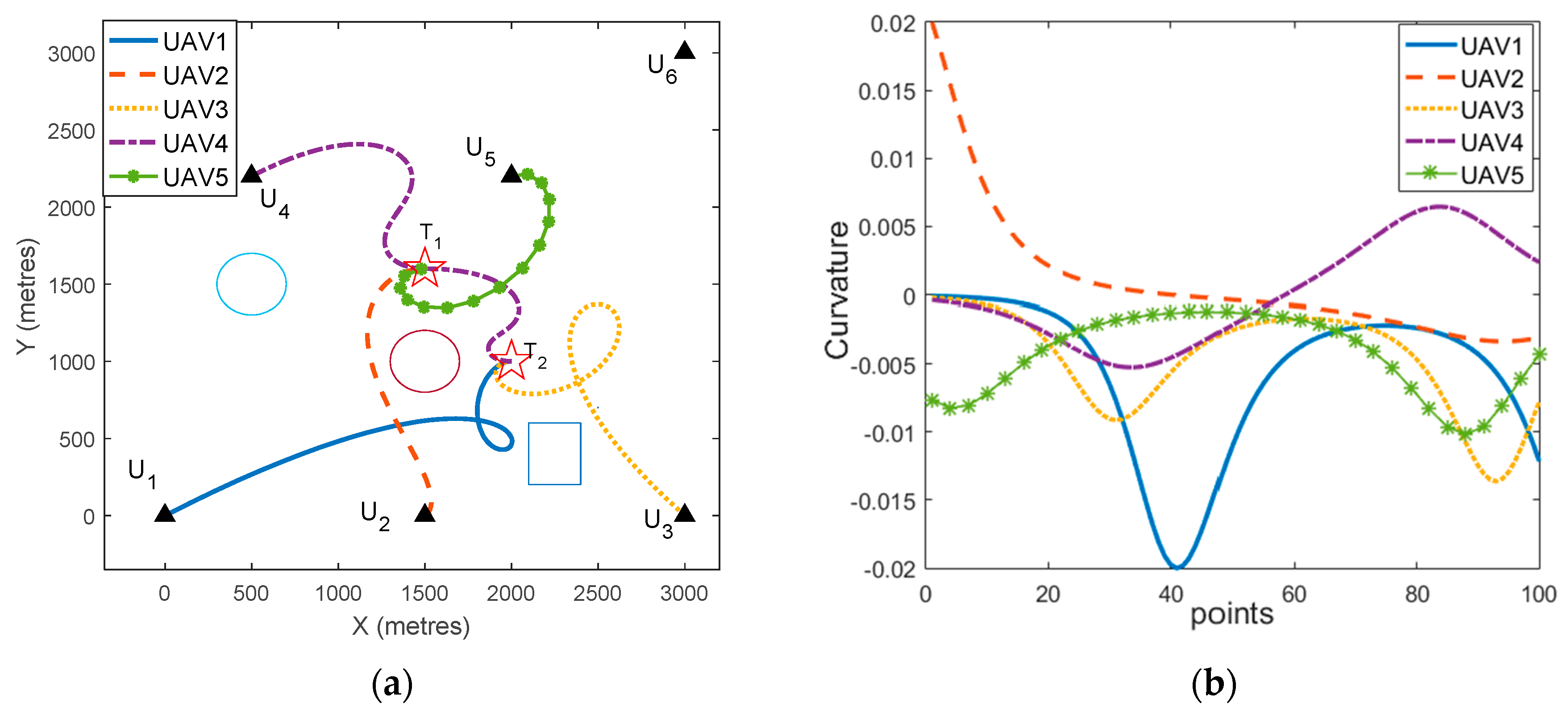
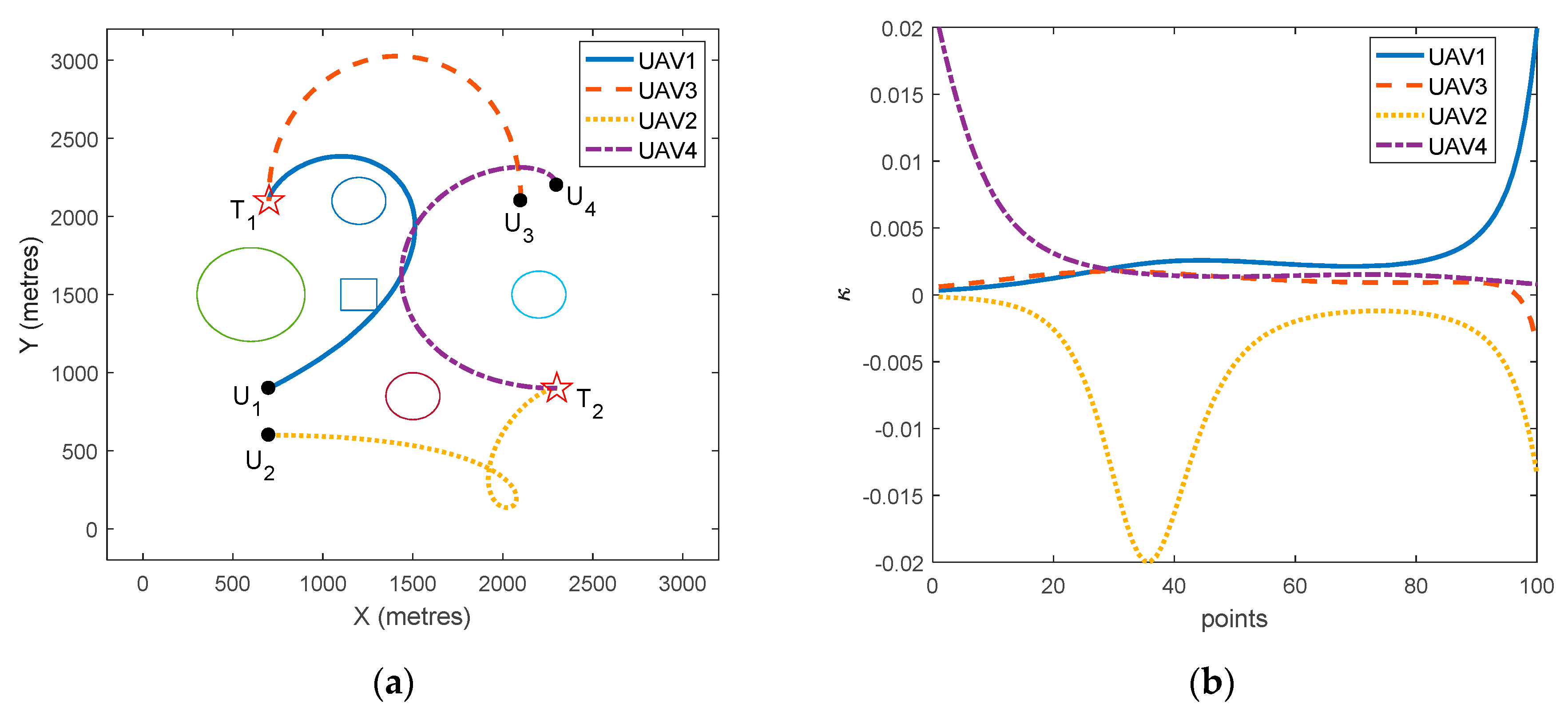
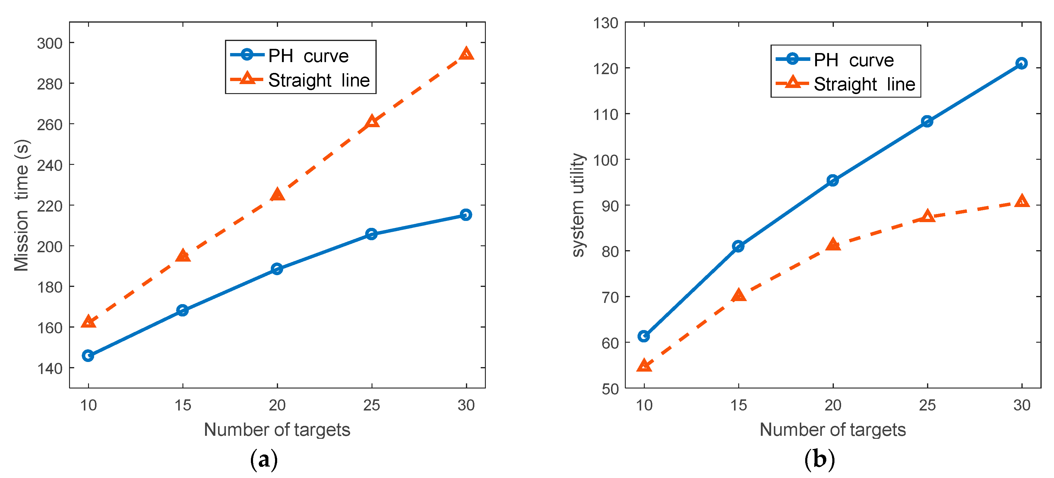
5.2. Effects of Different Path Estimation Methods on Task Allocation

Consider a scenario that involves four UAVs and two targets. The performance of the path estimation process using the PH curve was compared to that using a straight line. Four obstacles are in the region size 3200   m × 3200   m . The initial information of UAVs and targets are shown in Table 4 and Table 5. Other control parameters are the same with Section 5.1.
The UAVs used the proposed mission planning method to obtain the allocation strategy and feasible paths. When the straight line and PH curve were used in the path estimation process, the mission planning (task allocation and path planning) results are shown in Figure 4a and Figure 5a, respectively. The curvature of each UAV’s path of these two path estimation methods are shown in Figure 4b and Figure 5b, respectively, the curvature of each UAV’s path satisfied the maximum curvature constraint.
It can be seen from Figure 4 and Figure 5 that when the straight line and PH curve were used in the path estimation process, respectively, the task allocation methods generated different allocation strategies. When the straight line was used in the path estimation process, the generated coalitions were C 1 = [ U 1 , U 3 ] and C 2 = [ U 2 , U 4 ] for the target T 1 and T 2 , respectively. That was because the UAV U 1 was closer to target T 1 than target T 2 when the straight line was used in the path estimation. However, when there are obstacles in the environment, the path planning process should generate paths avoiding collision with obstacles, which will have a large deviation from the path estimation process using straight line. When path estimation using the PH curve was used in the mission planning method, it produced a more reasonable allocation strategy, the generated coalitions were C 1 = [ U 3 , U 4 ] and C 2 = [ U 1 , U 2 ] for the target T 1 and T 2 , respectively. Table 6 summarizes the results of these two path estimation methods for this study case. In Table 6, the mission time denotes the total time to perform all the targets, the system utility was calculated by Equation (6). It can be seen that, the mission time using the straight line in the path estimation was longer than that using the PH curve, which also led to a lower system utility.
In order for a deeper comparison of performance differences of the two path estimation methods, the performance of the two path estimation methods with increasement in the number of targets was compared by Monte Carlo simulation. In the set of simulation, there were six UAVs in the team, and the number of targets varied from 10 to 30. For each simulation, obstacles were taken into consideration. The location of UAVs and targets were randomly generated in a bounded region. Each target needed three different types of resources, each required resource was a random integer between three and five. Each UAV also carried three types of resources, and each type of resource was randomly generated between 20 and 30. Using two different path estimation methods, the comparison results of average mission completion time and system utility are shown in Figure 6.
Figure 6a shows the average mission time using the two path estimation methods when the number of targets increased. The vertical axis denotes the average mission completion time of 100 runs. The horizontal axis indicates the number of targets. When the PH curve was used in the path estimation process, it could obtain a smaller mission completion time compared to the path estimation using the straight line. That was because the deviation between the estimated path and the actual path was smaller, when the PH curve was used in the path estimation process. When the number of targets increased, the difference between the mission completion time of path estimation using the PH curve and straight-line increased.
Figure 6b shows the average system utility when using different path estimation methods. While the number of targets increasing, the system utility of the two path estimation methods increased. However, when the straight line was used in the path estimation process, the system utility increased slightly when the number of targets increased. It can be seen in Figure 6, the path estimation process using the PH curve had a much better performance than that using the straight line, especially when the number of targets increased.

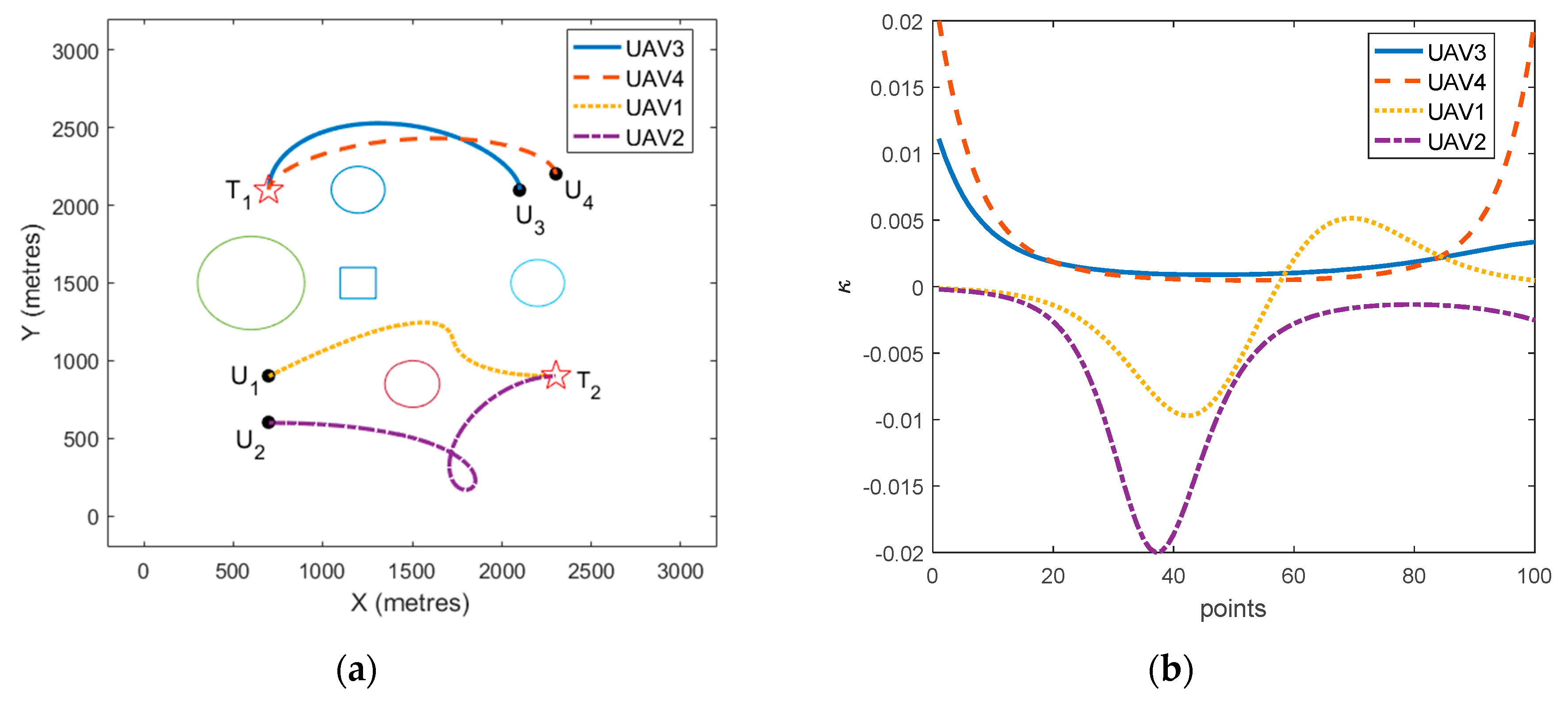
5.3. Comparison of Three Task Allocation Algorithms

The performance of the proposed task allocation algorithm was demonstrated in comparison with a PSO task allocation algorithm and a modified resource welfare-based [18] task allocation algorithm via Monte Carlo simulation. The system utility and mission computation time using different task allocation algorithms were compared.
For a comparative study, the resource welfare-based task allocation algorithm was modified to adapt to the problem in this paper. For a target to be assigned, the UAVs consumed resources in a balanced way, the coalition with the highest resource welfare was selected to attack the target simultaneously. Algorithm 1 was also used in the modified resource welfare-based task allocation algorithm, the Line 9 and 11 of algorithm 1 were replaced by the resource welfare method.
For the PSO-based task allocation algorithm, assuming there were N UAVs and M targets in the environment. The l t h particle at the k t h iteration in PSO task allocation algorithm is represented as:
X l k = ( x 11 l , k , , x 1 M l , k , x 21 l , k , , x 2 M l , k , , x N 1 l , k , x N 2 l , k , , x N M l , k )
where x i j l , k { 0 , 1 , , M } denotes that the UAV U i will attack target x i j l , k in j t h sequence. The dimension of each particle is N × M . Each particle represents a solution to the task allocation problem. The fitness of each particle can be calculated using Equation (6). If the task allocation solution represented by a particle violates the task allocation constraints in Equations (8)–(13), the fitness of this particle is set to 100 .
To compare the performance of the three task allocation algorithms, a set of simulation with different number of targets were designed. The parameter setting of these simulations is the same with the Monte Carlo simulation shown in Section 5.1. The PH curve was used in the path estimation process for all these task allocation algorithms. All these simulations used the proposed path planning method. The comparison results of the average mission completion time and system utility are shown in Figure 7. It should be noted that, as the dimension of the PSO-based algorithm was too large, we only recorded the feasible solutions obtained within 24 h of the PSO-based task allocation algorithm.
Figure 7a shows the comparison of the average mission completion time of these task allocation (TA) algorithms. Obviously, with the increase in the number of targets, the average mission completion time increased. When the number of targets was 10, the PSO-based task allocation algorithm could obtain the shortest mission completion time. However, the mission completion time using the PSO-based TA algorithm significantly increased with the number of targets. That was because when using the PSO-based TA algorithm, the dimension of particle was too high and increased with the number of targets, it was difficult for the PSO algorithm to obtain the optimal solution in a short time. From Figure 7a, the proposed TA algorithm performed better than the PSO-based and resource welfare-based TA algorithms.
Figure 7b presents the average system utility obtained by these TA algorithms. When the number of targets was 10, the PSO-based TA algorithm could obtain a higher system utility than the other two TA algorithms. However, with the increasing number of targets, the proposed algorithm outperformed the PSO-based TA algorithm as well as the resource welfare-based TA algorithm. That was because the PSO-based TA algorithm could not obtain the optimal solution when the dimension of the particle was high. This also led to a slight decline in the system utility when the number of targets increased further (the number of targets was 30) using the PSO-based TA algorithm.

6. Conclusions

In this paper, a hierarchical mission planning was proposed to decouple and solve the coupled task allocation and path planning problem for a multi-UAV attacking a multi-target. Three phases were involved in the method. In the path estimation process, each UAV utilized the PSO-based method to estimate the path length to targets. Then, a task allocation algorithm based on a negotiation mechanism was proposed to assign the targets. Finally, a path planning method was proposed to generate flyable and safe paths for the UAVs. Through the corresponding simulation, some key points were illustrated.
  • Considering the resource requirement of targets, UAV’s resource consumption and task sequence, the proposed task allocation algorithm could obtain feasible solutions for the UAVs.
  • The proposed path planning method could generate flyable and safe paths for the UAVs considering several constraints, such as simultaneous arrival, UAV’s kinematic and collision avoidance with obstacles.
  • The Monte Carlo results showed that path estimation using the PH curve performed better than that using the straight line. The proposed task allocation algorithm could obtain a lower mission completion time and higher system utility compared with the PSO algorithm and the modified resource welfare-based task allocation algorithm.
Although this paper focused on the problem of cooperative attacking using multiple UAVs, the proposed mission planning method can be applied to some civilian scenarios, such as multi-UAV cooperative fire fighting, where each UAV can carry different fire fighting resources. There are also some limitations in the proposed mission planning approach. The proposed task allocation algorithm assumes that all the UAVs can communicate with each other. Some practical issues that may appear in real environment, such as communication delay or even interruption will be considered in future work.

Author Contributions

Conceptualization, X.Z. and Z.Z.; methodology, F.Y.; software, F.Y.; formal analysis, F.Y.; writing—review and editing, F.Y. and J.C.

Funding

This research was funded by the Project 61703336 supported by National Nature Science Foundation of China.

Conflicts of Interest

The authors declare no conflict of interest.

References

  1. Wei, Z.Q.; Wu, H.C.; Huang, S.; Feng, Z.Y. Scaling Laws of Unmanned Aerial Vehicle Network with Mobility Pattern Information. IEEE Commun. Lett. 2017, 21, 1389–1392. [Google Scholar] [CrossRef]
  2. Zhen, Z.Y.; Xing, D.J.; Gao, C. Cooperative search-attack mission planning for multi-UAV based on intelligent self-organized algorithm. Aerosp. Sci. Technol. 2018, 76, 402–411. [Google Scholar] [CrossRef]
  3. Yuan, C.; Zhang, Y.M.; Liu, Z.X. A survey on technologies for automatic forest fire monitoring, detection, and fighting using unmanned aerial vehicles and remote sensing techniques. Can. J. Forest Res. 2015, 45, 783–792. [Google Scholar] [CrossRef]
  4. Sharma, V.; Nalin, K.; Jayakody, D.; Srinivasan, K.; Kumar, R. Coagulation Attacks over Networked UAVs: Concept, Challenges, and Research Aspects. Int. J. Eng. Technol. 2018, 7, 183–187. [Google Scholar] [CrossRef]
  5. Sharma, V.; Kumar, R. A Cooperative Network Framework for Multi-UAV Guided Ground Ad Hoc Networks. J. Intell. Robot. Syst. Theory Appl. 2014, 77, 629–652. [Google Scholar] [CrossRef]
  6. Yao, W.; Qi, N.; Wan, N.; Liu, Y. An iterative strategy for task assignment and path planning of distributed multiple unmanned aerial vehicles. Aerosp. Sci. Technol. 2019, 86, 455–464. [Google Scholar] [CrossRef]
  7. Yao, W.R.; Qi, N.M.; Liu, Y.F. Online Trajectory Generation with Rendezvous for UAVs Using Multistage Path Prediction. J. Aerosp. Eng. 2017, 30. [Google Scholar] [CrossRef]
  8. Meng, W.; He, Z.R.; Su, R.; Yadav, P.K.; Teo, R.; Xie, L.H. Decentralized Multi-UAV Flight Autonomy for Moving Convoys Search and Track. IEEE Trans. Control Syst. Technol. 2017, 25, 1480–1487. [Google Scholar] [CrossRef]
  9. Meng, W.; He, Z.R.; Teo, R.; Su, R.; Xie, L.H. Integrated multi-agent system framework: Decentralised search, tasking and tracking. Iet Control Theory Appl. 2015, 9, 493–502. [Google Scholar] [CrossRef]
  10. Edison, E.; Shima, T. Integrated task assignment and path optimization for cooperating uninhabited aerial vehicles using genetic algorithms. Comput. Oper. Res. 2011, 38, 340–356. [Google Scholar] [CrossRef]
  11. Wu, W.N.; Wang, X.G.; Cui, N.G. Fast and coupled solution for cooperative mission planning of multiple heterogeneous unmanned aerial vehicles. Aerosp. Sci. Technol. 2018, 79, 131–144. [Google Scholar] [CrossRef]
  12. Gottlieb, Y.; Shima, T. UAVs Task and Motion Planning in the Presence of Obstacles and Prioritized Targets. Sensors 2015, 15, 29734–29764. [Google Scholar] [CrossRef] [PubMed] [Green Version]
  13. Gerkey, B.P.; Matarić, M.J. A Formal Analysis and Taxonomy of Task Allocation in Multi-Robot Systems. Int. J. Robot. Res. 2004, 2004, 2004. [Google Scholar] [CrossRef]
  14. Ruan, L.; Chen, J.; Guo, Q.; Jiang, H.; Zhang, Y.; Liu, D. A Coalition Formation Game Approach for Efficient Cooperative Multi-UAV Deployment. Appl. Sci. 2018, 8, 2427. [Google Scholar] [CrossRef]
  15. Manathara, J.G.; Sujit, P.B.; Beard, R.W. Multiple UAV Coalitions for a Search and Prosecute Mission. J. Intell. Robot. Syst. 2011, 62, 125–158. [Google Scholar] [CrossRef]
  16. Sujit, P.B.; Manathara, J.G.; Ghose, D.; Sousa, J.B.D. Decentralized Multi-UAV Coalition Formation with Limited Communication Ranges. In Handbook of Unmanned Aerial Vehicles; Springer: Berlin/Heidelberg, Germany, 2015; pp. 2021–2048. [Google Scholar]
  17. Kim, M.H.; Baik, H.; Lee, S. Resource Welfare Based Task Allocation for UAV Team with Resource Constraints. J. Intell. Robot. Syst. 2015, 77, 611–627. [Google Scholar] [CrossRef]
  18. Sharma, V.; Reina, D.G.; Kumar, R. HMADSO: A novel hill Myna and desert Sparrow optimization algorithm for cooperative rendezvous and task allocation in FANETs. Soft Comput. 2018, 22, 6191–6214. [Google Scholar] [CrossRef]
  19. Oh, G.; Kim, Y.; Ahn, J.; Choi, H.L. Market-Based Task Assignment for Cooperative Timing Missions in Dynamic Environments. J. Intell. Robot. Syst. 2017, 87, 97–123. [Google Scholar] [CrossRef]
  20. Manathara, J.G.; Ghose, D. Rendezvous of Multiple UAVs with Collision Avoidance Using Consensus. J. Aerosp. Eng. 2012, 25, 480–489. [Google Scholar] [CrossRef]
  21. Lin, Z.J.; Hong-Tao, L.H. Consensus based on learning game theory with a UAV rendezvous application. Chin. J. Aeronaut. 2015, 28, 191–199. [Google Scholar] [CrossRef] [Green Version]
  22. Choe, R.; Puig-Navarro, J.; Cichella, V.; Xargay, E.; Hovakimyan, N. Cooperative Trajectory Generation Using Pythagorean Hodograph Bezier Curves. J. Guid. Control Dyn. 2016, 39, 1744–1763. [Google Scholar] [CrossRef]
  23. Ismail, A.; Bagula, B.A.; Tuyishimire, E. Internet-Of-Things in Motion: A UAV Coalition Model for Remote Sensing in Smart Cities. Sensors 2018, 18, 2184. [Google Scholar] [CrossRef]
  24. Tsourdos, A.; White, B.; Shanmugavel, M. Cooperative Path Planning of Unmanned Aerial Vehicles; Wiley: Weinheim, Germany, 2010; pp. 1601–1602. [Google Scholar]
  25. Xiang, Y.; Zhang, Y. Sense and avoid technologies with applications to unmanned aircraft systems: Review and prospects. Prog. Aerosp. Sci. 2015, 74, 152–166. [Google Scholar]
  26. Shanmugavel, M.; Tsourdos, A.; White, B.; Zbikowski, R. Co-operative path planning of multiple UAVs using Dubins paths with clothoid arcs. Control Eng. Pract. 2010, 18, 1084–1092. [Google Scholar] [CrossRef]
  27. Vachtsevanos, G.J.; Tang, L.; Drozeski, G.; Gutierrez, L. From mission planning to flight control of unmanned aerial vehicles: Strategies and implementation tools. Annu. Rev. Control 2005, 29, 101–115. [Google Scholar] [CrossRef]
  28. Pierpaoli, P.; Rahmani, A. UAV collision avoidance exploitation for noncooperative trajectory modification. Aerosp. Sci. Technol. 2018, 73, 173–183. [Google Scholar] [CrossRef]
  29. Farouki, R.T.; Giannelli, C.; Mugnaini, D.; Sestini, A. Path planning with Pythagorean-hodograph curves for unmanned or autonomous vehicles. Proc. Inst. Mech. Eng. Part G J. Aerosp. Eng. 2018, 232, 1361–1372. [Google Scholar] [CrossRef]
  30. Farouki, R.T. Construction of G 1 planar Hermite interpolants with prescribed arc lengths. Comput. Aided Geom. Des. 2016, 46, 64–75. [Google Scholar] [CrossRef] [Green Version]
  31. Yan, F.; Zhu, X.; Zhou, Z.; Tang, Y. Heterogeneous multi-unmanned aerial vehicle task planning: Simultaneous attacks on targets using the Pythagorean hodograph curve. Proc. Inst. Mech. Eng. Part G J. Aerosp. Eng. 2019. [Google Scholar] [CrossRef]
Figure 1. Integration framework of task allocation, path planning and path following.
Applsci 09 01986 g001
Figure 2. (a) The mission planning results for two targets; (b) curvature of each UAV’s path.
Applsci 09 01986 g002
Figure 3. (a) The ETA for the target T 1 ; (b) the ETA for the target T 2 .
Applsci 09 01986 g003
Figure 4. (a) Mission planning results (straight line is used in the path estimation process); (b) curvature of each UAVs’ path.
Applsci 09 01986 g004
Figure 5. (a) Mission planning results (Pythagorean hodograph (PH) curve is used in the path estimation process); (b) curvature of each UAVs’ path.
Applsci 09 01986 g005
Figure 6. Comparison of the two path estimation methods. (a) Average mission completion time; (b) average system utility.
Applsci 09 01986 g006
Figure 7. Comparison of these task allocation (TA) algorithms. (a) Average mission completion time; (b) average system utility.
Applsci 09 01986 g007
Table 1. The initial information of the targets.
TargetsInitial Location (m)Resource RequirementInitial Value
Target 1 ( 1500 , 1600 ) ( 4 , 2 ) 100
Target 2 ( 2000 , 1000 ) ( 5 , 4 ) 90
Table 2. The initial information of the unmanned aerial vehicles (UAVs).
UAVsInitial Location (m)Heading Angle (rad)Initial Resource
UAV 1 ( 0 , 0 ) p i / 6 ( 2 , 1 )
UAV 2 ( 1500 , 0 ) p i / 6 ( 1 , 0 )
UAV 3 ( 3000 , 0 ) 3 4 / p i ( 3 , 2 )
UAV 4 ( 500 , 2200 ) p i / 6 ( 2 , 2 )
UAV 5 ( 2000 , 2000 ) p i / 6 ( 1 , 1 )
UAV 6 ( 3000 , 3000 ) 3 4 / p i ( 2 , 1 )
Table 3. Control parameters in the proposed mission planning method.
ParametersNotationValue
Descent rate of target’s reward β 0.05
The minimum turning radius of the UAV R min 50 m
Weight value of the target reward in Equation (6) w 1 0.8
Weight value of the cost in Equation (6) w 2 0.2
Weight value in Equation (25) w 0.8
Velocity of the UAVs V 50   m / s
Population size of the PSO algorithm M p 50
Acceleration coefficient of the PSO algorithm c 1 2
Acceleration coefficient of the PSO algorithm c 2 2
Table 4. Initial information of UAVs.
UAVsInitial Location (m)Heading Angle (rad)Initial Resource
UAV 1 ( 700 , 900 ) p i / 6 ( 2 , 2 )
UAV 2 ( 700 , 600 ) 0 ( 2 , 2 )
UAV 3 ( 2100 , 2100 ) p i / 2 ( 2 , 2 )
UAV 4 ( 2300 , 2200 ) p i / 2 ( 2 , 2 )
Table 5. Targets location and resource requirement.
TargetsInitial Location (m)Resource RequirementInitial Value
Target 1 ( 700 , 2100 ) ( 4 , 4 ) 100
Target 2 ( 2300 , 900 ) ( 4 , 4 ) 90
Table 6. Performance of different path estimation methods.
Figure #Path Estimation Mission Time (s)System Utility
4aStraight line51.71.3
5aPH curve35.626.5

