Using Small Capacity Fuel Cells Onboard Drones for Battery Cooling: An Experimental Study


Abstract
1. Introduction
2. System Overview
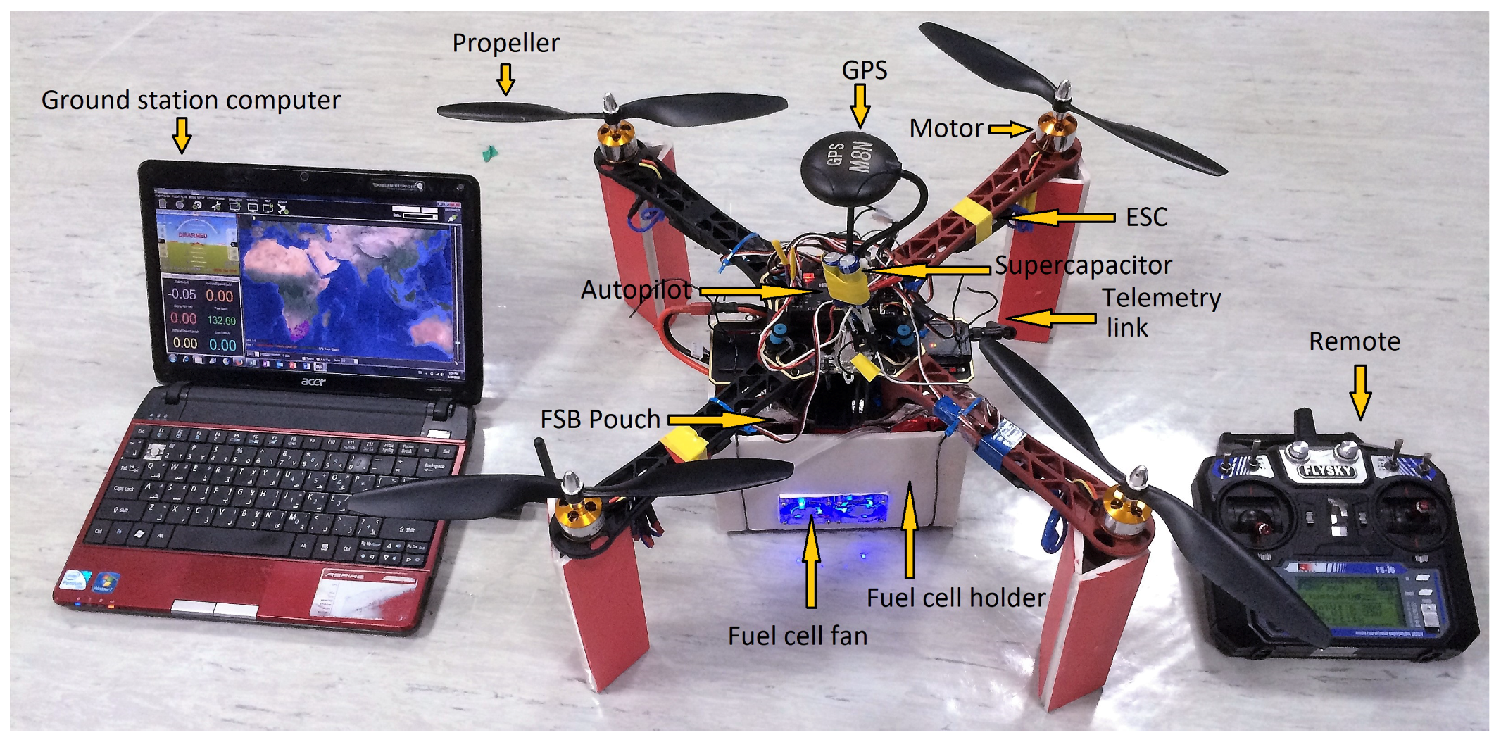
2.1. Hardware
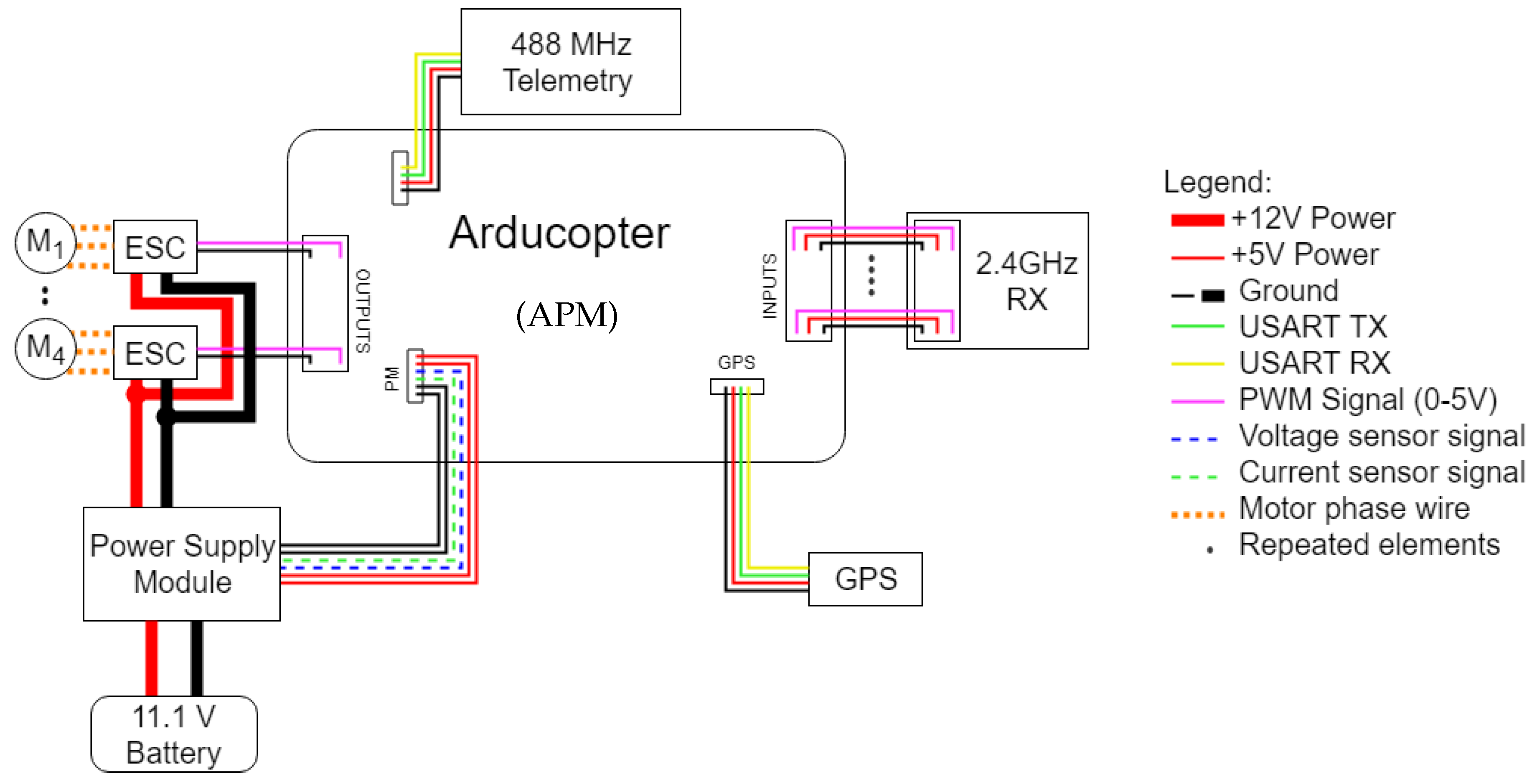
2.2. Electrical System Schematic without Fuel Cell Stack and Supercapacitor
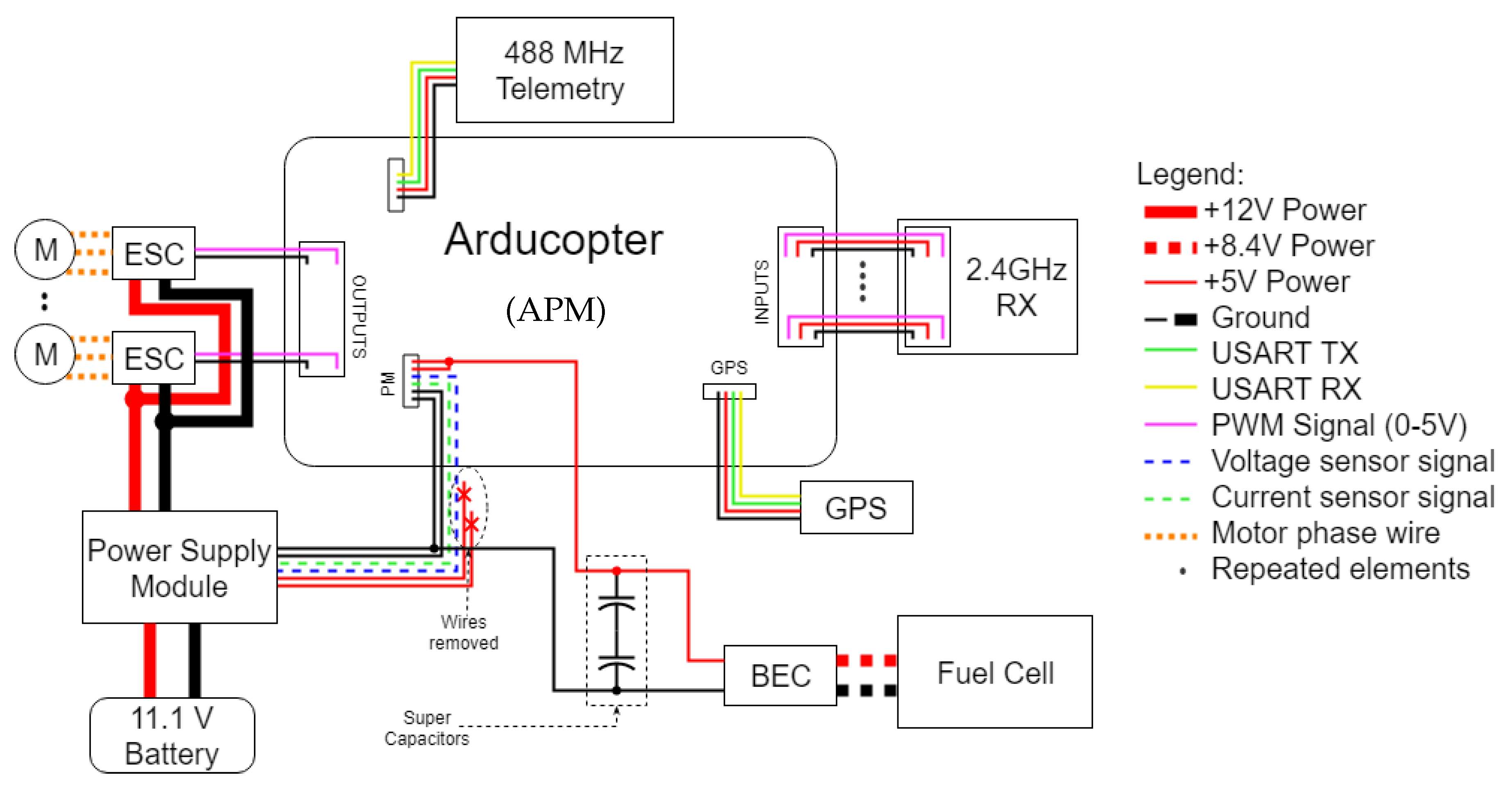
2.3. Electrical System Schematic with Fuel Cell Stack and Supercapacitor
2.4. Ground Station Software
3. Experiments and Results
3.1. Experimental Setup
3.2. Experimental Results
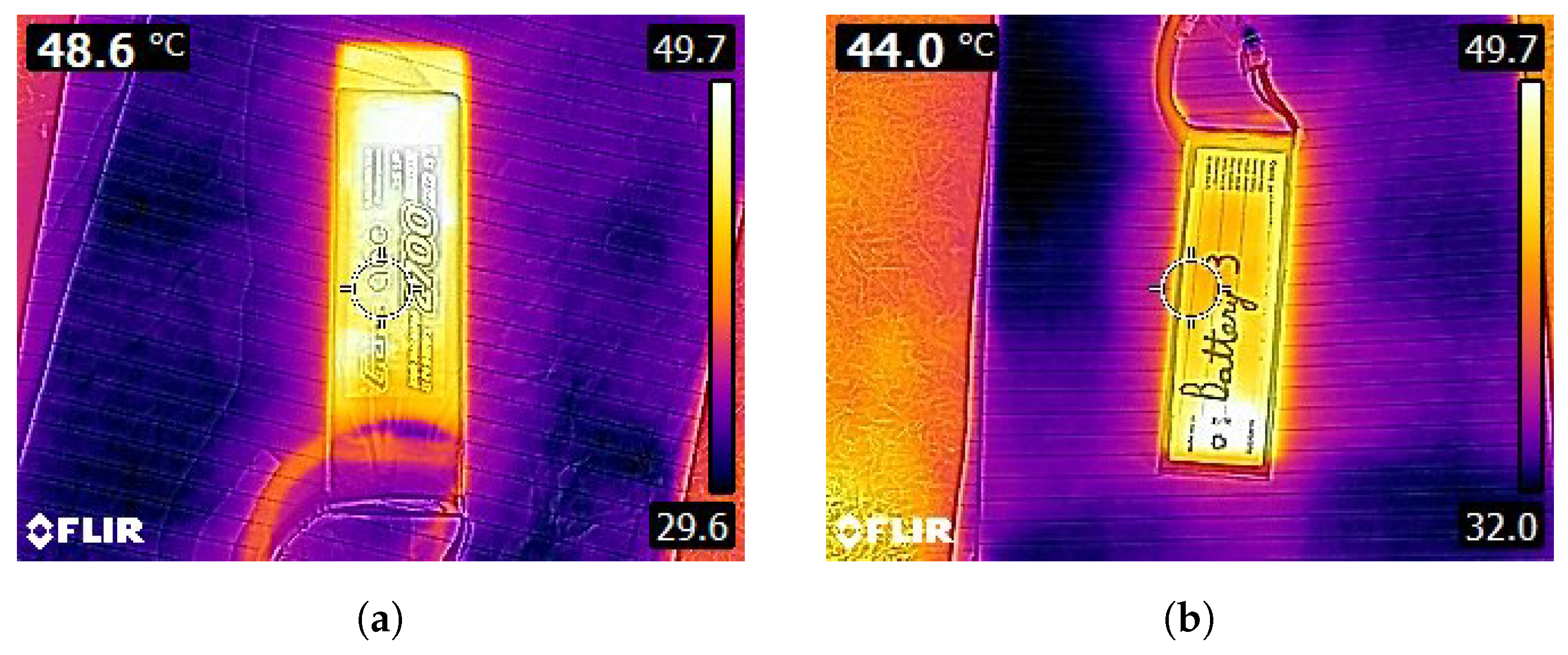
3.2.1. Cooling Effect Produced by Fuel Cells
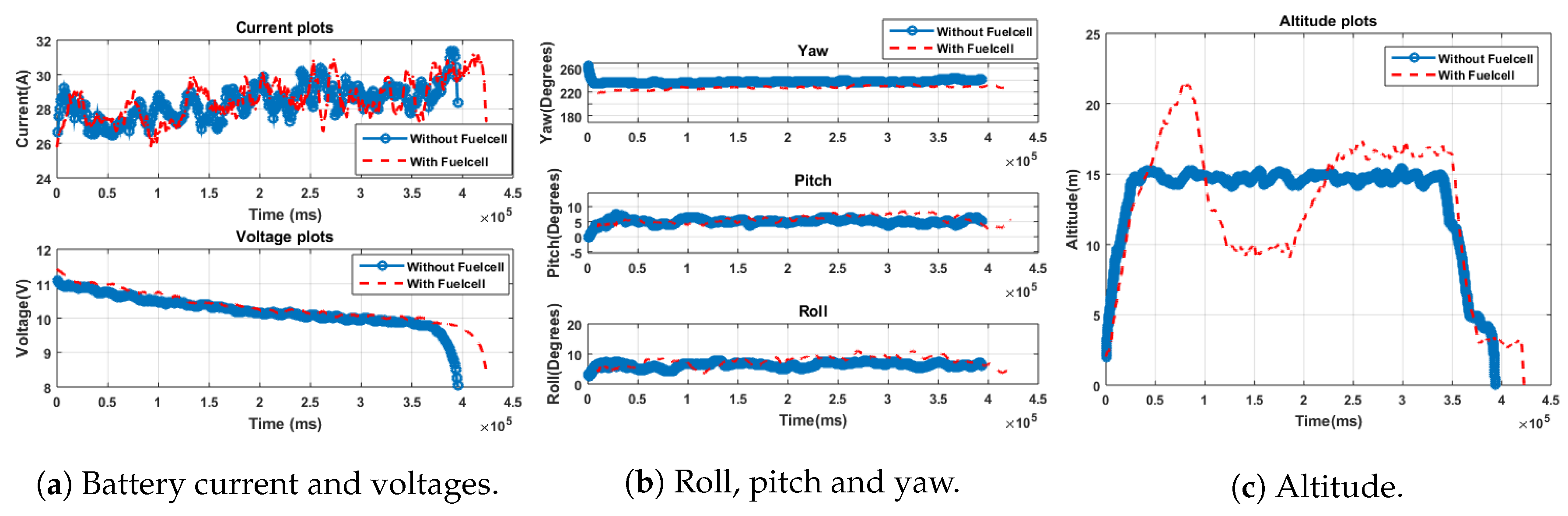
3.2.2. Results of Cooling Batteries Onoard Drones with/without a Fuel Stick
4. Conclusions
Future Work
Author Contributions
Acknowledgments
Conflicts of Interest
References
- Ackerman, E.; Strickland, E. Medical delivery drones take flight in east Africa. IEEE Spectr. 2018, 55, 34–35. [Google Scholar] [CrossRef]
- Chung, A.Y.; Lee, J.Y.; Kim, H. Autonomous Mission Completion System for Disconnected Delivery Drones in Urban Area. In Proceedings of the 2017 IEEE International Conference on Robotics and Biomimetics (ROBIO), Macau, China, 5–8 December 2017; pp. 56–61. [Google Scholar]
- Lim, J.; Jung, H. Drone Delivery Scheduling Simulations Focusing on Charging Speed, Weight and Battery Capacity: Case of Remote Islands in South Korea. In Proceedings of the Winter Simulation Conference (WSC), Las Vegas, NV, USA, 3–6 December 2017; pp. 4550–4551. [Google Scholar]
- Park, S.; Zhang, L.; Chakraborty, S. Battery Assignment and Scheduling for Drone Delivery Businesses. In Proceedings of the IEEE/ACM International Symposium on Low Power Electronics and Design (ISLPED), Taipei, Taiwan, 24–26 July 2017; pp. 1–6. [Google Scholar]
- Dorling, K.; Heinrichs, J.; Messier, G.G.; Magierowski, S. Vehicle Routing Problems for Drone Delivery. IEEE Trans. Syst. Man Cybern. Syst. 2017, 47, 70–85. [Google Scholar] [CrossRef]
- Gonzalez, T.; David, J.; Fung, W.K. A Pilot Study on Aeronautical Surveillance System for Drone Delivery Using Heterogeneous Software Defined Radio Framework. In Proceedings of the IEEE International Conference on Real-time Computing and Robotics (RCAR), Okinawa, Japan, 14–18 July 2017; pp. 499–504. [Google Scholar]
- Linden, D.; Reddy, T.B. Handbook of Batteries, 3rd ed.; McGraw-Hill: New York, NY, USA, 2002. [Google Scholar]
- Saw, L.; Tay, A.A.O.; Zhang, L.W. Thermal Management of Lithium-Ion Battery Pack with Liquid Cooling. In Proceedings of the 31st IEEE Thermal Measurement, Modeling & Management Symposium (SEMI-THERM), San Jose, CA, USA, 15–19 March 2015; pp. 298–302. [Google Scholar]
- Madani, S.; Schaltz, E.; Knudsen Kær, S. Review of Parameter Determination for Thermal Modeling of Lithium Ion Batteries. Batteries 2018, 4, 20. [Google Scholar] [CrossRef]
- De Hoog, J.; Jaguemont, J.; Abdel-Monem, M.; Van Den Bossche, P.; Van Mierlo, J.; Omar, N. Combining an Electrothermal and Impedance Aging Model to Investigate Thermal Degradation Caused by Fast Charging. Energies 2018, 11, 804. [Google Scholar] [CrossRef]
- Koch, S.; Birke, K.; Kuhn, R. Fast Thermal Runaway Detection for Lithium-Ion Cells in Large Scale Traction Batteries. Batteries 2018, 4, 16. [Google Scholar] [CrossRef]
- Bhide, S.; Shim, T. Novel Predictive Electric Li-Ion Battery Model Incorporating Thermal and Rate Factor Effects. IEEE Trans. Veh. Technol. 2011, 60, 819–829. [Google Scholar] [CrossRef]
- Xiao, Y. Model-Based Virtual Thermal Sensors for Lithium-Ion Battery in EV Applications. IEEE Trans. Ind. Electron. 2015, 62, 3112–3122. [Google Scholar] [CrossRef]
- Saw, L.; Ye, Y.; Tay, A. Electro-thermal characterization of Lithium Iron Phosphate cell with equivalent circuit modeling. Energy Convers. Manag. 2014, 87, 367–377. [Google Scholar] [CrossRef]
- Ali, D.; Mukhopadhyay, S.; Rehman, H.; Khurram, A. UAS based Li-ion battery model parameters estimation. Control Eng. Pract. 2017, 66, 126–145. [Google Scholar] [CrossRef]
- Klein, R.; Chaturvedi, N.A.; Christensen, J.; Ahmed, J.; Findeisen, R.; Kojic, A. Electrochemical Model Based Observer Design for a Lithium-Ion Battery. IEEE Trans. Control Syst. Technol. 2013, 21, 289–301. [Google Scholar] [CrossRef]
- Mukhopadhyay, S.; Zhang, F. A high-gain adaptive observer for detecting Li-ion battery terminal voltage collapse. Automatica 2014, 50, 896–902. [Google Scholar] [CrossRef]
- Belmonte, N.; Staulo, S.; Fiorot, S.; Luetto, C.; Rizzi, P.; Baricco, M. Fuel cell powered octocopter for inspection of mobile cranes: Design, cost analysis and environmental impacts. Appl. Energy 2018, 215, 556–565. [Google Scholar] [CrossRef]
- Lee, B.; Kwon, S.; Park, P.; Kim, K. Active power management system for an unmanned aerial vehicle powered by solar cells, a fuel cell, and batteries. IEEE Trans. Aerosp. Electron. Syst. 2014, 50, 3167–3177. [Google Scholar] [CrossRef]
- Lindahl, P.; Moog, E.; Shaw, S.R. Simulation, Design, and Validation of an UAV SOFC Propulsion System. IEEE Trans. Aerosp. Electron. Syst. 2012, 48, 2582–2593. [Google Scholar] [CrossRef]
- ArduPilot Mega, the Open Source Autopilot. Available online: https://www.ardupilot.co.uk (accessed on 5 June 2018).
- Mission Planner. Available online: http://ardupilot.org/planner/docs/mission-planner-overview.html (accessed on 5 June 2018).
- Horizon Educational. Available online: http://www.horizoneducational.com (accessed on 5 June 2018).
- Vasiliev, L.; Vasiliev, L., Jr. Mini-Micro Fuel Cells: Fundamentals and Applications; Chapter-Heat Transfer Enhancement in Confined Spaces of Mini-Micro Fuel Cells; Kakaç, S., Pramuanjaroenkij, A., Vasiliev, L., Eds.; Springer: Berlin/Heidelberg, Germany, 2008. [Google Scholar]


| Item | Description |
|---|---|
| Fuel Cell Type | Proton Exchange Membrane (PEM) |
| No. of cells | 14 |
| Rated output power | 30 W |
| Typical voltage and current output | 8.4 V, 3.6 A |
| Purge valve voltage | 6 V |
| Controller voltage | 5 V |
| Reactants | Hydrogen and air |
| Maximum stack temperature | 55 C |
| Hydrogen pressure | 0.45–0.55 bar |
| Humidification | Self-humidified |
| Cooling | Air (via integrated cooling fan) |
| Dimensions | 8 cm × 4.7 cm × 7.5 cm |
| Flow rate at maximum output | 0.42 L/min |
| Start-up time | ≤30 s |
| Stack efficiency | 40% at rated power |
| Stack weight | 280 g (±30 g) |
| Controller weight | 90 g (±10 g) |
| Item | Description |
|---|---|
| Capacity | 10 L |
| Storage material | AB5 metal hydride |
| Cylinder material | Aluminium |
| Cartridge size | 22 mm (diameter) × 88 mm (height) |
| Weight | Approximately 105 g |
| Rated charging pressure | 3 MPa |
| Typical discharging performance | 0.3–0.5 L/min |
| Working temperature | 0–55 C |
| Service life | 10 years |
| Item | Drone Chassis with Battery | Fuel Cell Holder Box with all Required Components (Including Fuel Stick and Pressure Regulator) | Prototype Aluminium Foil Cooling Jacket |
|---|---|---|---|
| Weight (g) | 1200 | 525.46 | 24.552 |
| Flight | Battery Temperature | C) | Flight | Flight | |
|---|---|---|---|---|---|
| Test | Takeoff | Landing | (Decrease in Battery Temperature | Time | Time Gained |
| Name | C | C | Using the Fuel Stick) | (minutes) | (seconds) |
| 1 | 30.11 | 52.63 | N/A | 6.58 | N/A |
| 2 | 30.33 | 48.27 | 4.36 | 7.06 | 28.8 |
| 3 | 24.1 | 45.9 | N/A | 6.44 | N/A |
| 4 | 26.9 | 37.8 | 8.1 | 6.61 | 10.2 |
| 5 | 23.4 | 48.6 | N/A | 5.62 | N/A |
| 6 | 28 | 44.0 | 4.6 | 6.31 | 41.4 |
| 7 | 29.2 | 46.4 | N/A | N/A | N/A |
| 8 | 34 | 42.7 | 3.7 | N/A | N/A |
© 2018 by the authors. Licensee MDPI, Basel, Switzerland. This article is an open access article distributed under the terms and conditions of the Creative Commons Attribution (CC BY) license (http://creativecommons.org/licenses/by/4.0/).
Share and Cite
Mukhopadhyay, S.; Fernandes, S.; Shihab, M.; Waleed, D. Using Small Capacity Fuel Cells Onboard Drones for Battery Cooling: An Experimental Study. Appl. Sci. 2018, 8, 942. https://doi.org/10.3390/app8060942
Mukhopadhyay S, Fernandes S, Shihab M, Waleed D. Using Small Capacity Fuel Cells Onboard Drones for Battery Cooling: An Experimental Study. Applied Sciences. 2018; 8(6):942. https://doi.org/10.3390/app8060942
Chicago/Turabian StyleMukhopadhyay, Shayok, Sheehan Fernandes, Mohammad Shihab, and Danial Waleed. 2018. "Using Small Capacity Fuel Cells Onboard Drones for Battery Cooling: An Experimental Study" Applied Sciences 8, no. 6: 942. https://doi.org/10.3390/app8060942
APA StyleMukhopadhyay, S., Fernandes, S., Shihab, M., & Waleed, D. (2018). Using Small Capacity Fuel Cells Onboard Drones for Battery Cooling: An Experimental Study. Applied Sciences, 8(6), 942. https://doi.org/10.3390/app8060942