1. Introduction
The inhalation of aerosols has played a pivotal role in the vistas of pulmonary drug delivery since ancient times, as a way of relieving respiratory diseases [
1,
2,
3]. From a medical perspective, “aerosol therapy” is medical terminology, which is used to describe a variety of treatment techniques, including the delivery of a variety of drugs that may be administered via inhalation, targeting lung tissues and airway secretions in the upper, central, and peripheral airways [
4,
5]. These drug-delivery strategies have several advantages compared with conventional methods of oral administration. First, aerosol methods have the advantages of a direct and simple delivery of medication to the site where action is required [
6]. This produces a more rapid therapeutic effect. In addition, another important benefit of these strategies is that less medication can be used to obtain the same therapeutic effects, compared to systemically-delivered medication. As a consequence, inhalation therapy can be an extremely effective method in the field of drug delivery systems [
7,
8,
9]. In practice, these drug delivery techniques developed rapidly in the 1950s, with the development of nebulizers and pressurized metered-dose inhalers. In addition, there have been advances in the development of new nebulizers that hold promise in improving aerosol drug delivery in patients with pulmonary diseases [
10,
11,
12].
Nebulizer therapy is a traditional and common instrumental therapeutic method consisting of supplying a drug to a patient’s air-passages in the form of an aerosol, namely, the supply of tiny solid particles suspended in gas or liquid [
13,
14,
15,
16]. Generally, there are three types of conventional nebulizer equipment: jet nebulizers, ultrasonic nebulizers, and mesh nebulizers. Air-jet nebulizers generate drug aerosols by using the energy provided by compressed gas [
17]. The jet stream generated by high-speed gas is passed through a narrow Venturi tube and an area of negative pressure, where the air jet emerges and draws liquid from a reservoir, up a feed tube. However, jet nebulization causes the formation of solvent vapor, which saturates outgoing air. The generated solvent vapor cools down the nebulizer fluid and results in an increase in solute concentration in the residual fluid [
18]. The drawback of this method is the need for a source of compressed gas and its inherent inefficiency. Ultrasonic nebulizers generate aerosols using a high-frequency vibrating piezoelectric crystal, producing a fountain at the air–liquid interface. However, excessive frequency energy is converted to heat, causing the temperature of the liquid within the nebulizer to increase [
19,
20]. Therefore, this method can lead to serious thermal denaturalization of therapeutic agents. Practically, traditional ultrasonic nebulizers are also inefficient for delivering suspensions and viscous liquids [
8,
21]. To overcome these problems, new types of vibrating-mesh nebulizers have been developed in recent years. In this method, a piezoelectric crystal within the nebulizer induces vibrations that are transmitted to an adjacent mesh with multiple apertures [
22]. This result causes the extrusion of fluid through the apertures to generate aerosols [
22]. Commercial products using this technology include Aeroneb (Aerogen, Galway, Ireland), MicroAir (Omron, Vernon Hills, IL, USA), eFlow (PARI, Midlothian, VA, USA), and I-neb (Respironics, Murrysville, PA, USA) [
23]. A silicone-based mesh has also been introduced recently [
24]. This new technology offers many features and practical advantages, such as an increased fine particle fraction due to standardized micro-perforations, a higher output rate of inhaled medication, improved portability, and easier handling [
25]. However, the vibrating mesh nebulizers require daily cleaning and sanitization protocols to keep the meshes from becoming clogged over time, which can change the aerosol output rate and aerosol droplet size distribution [
26]. Furthermore, despite all these technical developments, the biological safety and durability of these products have not been addressed, even though many people use these devices. Durability is a very important factor because the metal mesh can be broken by continuous ultrasonic vibrations. If the metal mesh is broken, tiny pieces of broken metal can have harmful effects on human beings, when they are circulating or accumulated in the body. Therefore, it is very important to ensure the safety and durability of this device.
The aim of this research is to develop a micro-porous mesh nebulizer with biocompatibility and durability. Most important is to develop a controllable Pd–Ni membrane filter in mesh nebulizer devices, such that drug delivery efficiency is maximized. In order to achieve these goals, micro-pump technology, consisting of piezoelectric inkjet print heads, is suggested as the key component of the Pd–Ni membrane filter for the generation of micro-aerosol [
27]. The driving mechanism of nebulization in this device was completed through the integration of the piezoelectric element, micro-porous Pd–Ni membrane filter, and the cavity of the pump. A Pd–Ni membrane filter, which minimizes the toxicity of Ni, was fabricated by applying a two-step procedure involving lithography and electroplating processes. The morphology and structural properties of the Pd–Ni membrane filter were investigated via scanning electron microscopy, X-ray diffraction, and atomic absorption spectroscopy. The nebulized liquid droplet sizes of various drugs were directly measured using a sophisticated laser diffraction particle-size analyzer.
2. Materials and Methods
2.1. Fabrication of the Pd–Ni Membrane Filter
During the process of manufacturing the Pd–Ni membrane filter, all experiments were performed in a clean room with a class of 1000. The relative humidity and temperature were ~50% and ~25 °C, respectively. Our experiments did not consider throughput.
The Pd–Ni membrane filter was fabricated using lithography and electroplating processes to generate micro-porous nozzles. First, the lithography process was used to form micro-patterns. The substrates used for the lithographic study were 6-inch brass-rolled strips with surfaces polished by an etching solution. A positive photoresist (PR, AZGXR-601) of about 5 mL was static-dispensed onto the brass substrate and immediately followed by spinning. The spin speed and coating time of the spin-coating process were approximately 1000 rpm and 1 min, respectively. High aspect ratios were achieved by conducting the exposure process under a patterned photomask. The UV lamp was a 350 W high-pressure mercury lamp, and the typical UV intensity was 10 W/cm2 at 365 nm for 8 s. After the exposure process, the patterned substrate was developed in an aqueous developer (AZ300MIF), which was diluted five times using deionized water, at room temperature.
This study used fluorine compound passivation treatment as a release reagent under specific operating conditions to generate a passivation layer above the brass substrate. This passivation layer enabled the electroformed Pd–Ni alloy filter of the nebulizer to be easily released from the brass substrate. The micro-electroplating technique was used to electrodeposit metals into the structure, defined by a column-like pattern. Electroforming of the Pd–Ni alloy membrane filter using a fountain-type electroforming machine developed in this study and Pd–Ni electrolytic bath was effective in shrinking the holes to the desired diameter (
Figure 1). The electrolytes flowing through the anode titanium net-type plate came into contact with the fixed brass cathode. The metal ion ratio of Pd to Ni was 1:1 in the electrolyte solution. The reaction temperature and pH were approximately 48 °C and 8, respectively. After the electroforming process, the brass substrate was removed and the residual photoresists were washed several times with a chemical solvent.
2.2. Characterization of the Pd–Ni membrane Filter
The surface morphology and topography of the microporous Pd–Ni membrane filter were observed using field-emission scanning electron microscopy (FESEM, Hitachi, SU–70, Tokyo, Japan) and energy dispersive X-ray spectroscopy (EDS, Oxford, AZtecOneXT, Abingdon, UK), respectively. The crystallographic characteristics and nanostructure of the microporous Pd–Ni membrane filter were investigated with an X-ray diffractometer (PANalytical, X’Pert Pro MPD, Almelo, The Netherlands) operated at 40 kV and 150 mA in the 2θ range of 30–90°. Quantitative analysis of the Pd and Ni content ratio was carried out using inductively-coupled plasma mass spectrometry (ICP-MS, SQ-ICP-MS, Thermo Fisher Scientific, Waltham, MA, USA). The micro-hardness of the micro-porous Pd–Ni membrane filter was measured with a Vickers hardness tester (HMV2 Micro Vickers Hardness Tester, Shimadzu, Kyoto, Japan).
2.3. Biocompatibility Assessment
The biocompatibility of the micro-porous membrane filter was evaluated by performing cytotoxicity tests, using L-929 (mouse fibroblast) and A-549 (human alveolar basal epithelial cell) cells, using two recommended methods: A direct contact method and an extract dilution method, which have been previously described [
28,
29]. The two types of cells were cultured in Dulbecco’s modified Eagle’s medium (DMEM) containing 4 mM
l-glutamine, 1.5 g/L sodium bicarbonate, 4.5 g/L
d-glucose, 1.0 mM sodium pyruvate, 10% fetal bovine serum, and 1% antibiotic antimycotic solution, including 10,000 units of penicillin, 10 mg of streptomycin, and 25 g of amphotericin B per mL (Sigma-Aldrich Co., St. Louis, MO, USA).
The morphology of the cells was visualized under the micro-porous membrane filter using the direct contact method by transfecting the L-929 and A-549 cells with green fluorescent protein (GFP), as previously described [
30,
31]. Briefly, films of high-density polyethylene (HDPE, thickness 0.5 mm), a negative control, and polyurethane containing zinc diethyldithiocarbamate (PU-ZDEC, thickness 0.5 mm), a positive control, were supplied by the Hatano Research Institute’s Food and Drug Safety Center, and the films (1 × 1 cm
2) were sterilized using ethylene oxide gas for use as the negative and positive controls. Pre-cultured GFP-transfected L-929 and A-549 cells were plated in 6-well plates (Costar Corp., Greenwich, CT, USA) at 1.5 × 10
5 cells per well, and the plates were pre-incubated for 24 h at 37 °C in an incubator (5% CO
2 conditions). The samples, the Pd–Ni membrane filter, and the HDPE and PU-ZDEC films were overlaid onto the cells to form a confluent monolayer in the center of each well, and were further incubated for 24 h. To confirm the morphological changes by the Pd–Ni membrane filter, the GFP-transfected L-929 and A-549 cells in each well were imaged using an automated imaging reader (Cytation 3; BioTek Instrument, Inc., Winooski, VT, USA) with fluorescence optics (excitation at 465 nm and emission at 503 nm).
Assessment of the biocompatibility of the Pd–Ni membrane filter using an extract dilution method as previously described [
28] was achieved by placing the samples, Pd–Ni membrane filter, HDPE, and PU-ZDEC films in screw-capped tubes containing 2x DMEM and agitated at 100 rpm for 48 h in a 37 °C incubator. After incubation, the extracts were then serially diluted, two-fold, by adding fresh media containing FBS. The L-929 and A-549 cells were plated in the 24-well plate and incubated with the same density of cells and conditions as described above. After incubating for 24 h, the medium was replaced with diluted extract media and incubated under the same conditions for a further 24 h. The cells were incubated with a Cell Counting Kit-8 (CCK-8) solution (Dojindo Laboratories, Kumamoto, Japan) for 15 min after washing three times with DPBS. The cell viabilities in each sample were calculated by measuring the absorbance of each well at 450 nm on a multimodal micro-plate reader (Cytation 3). Cell viability was expressed as a percentage of surviving cells in relation to the number of control cells.
2.4. Assessment of the Size of Nebulized Liquid Droplets
The particle size and distributions of the nebulized liquid droplet were measured directly using a laser diffraction method. A sophisticated laser diffraction particle-size analyzer (Malvern Panalytical, Spraytec, Malvern, UK) was used to serially measure the size distribution of nebulized particles that passed through the laser detection fields at 1 s intervals for the duration of the nebulization. With the receiver lens attached, droplets with diameters between 0.1 and 100 μm could be measured. This system included a laser, optics, detectors, gathering of data, and analytical software. The nebulized liquid droplet size was measured using deionized water, amphetamine (10 mg/mL), and levofloxacin (10 mg/mL) as the delivery drug.
2.5. Statistical Analyses
All samples that were subjected to biocompatibility testing were tested in duplicate, and each experiment was repeated twice (n = 4). The quantitative analysis data were expressed as the mean ± standard deviation (SD). Statistical comparisons were performed with a Student’s t-test and significant differences were indicated by using a value of p < 0.05.
3. Results and Discussion
The process for fabricating the micro-porous Pd–Ni membrane filter consists of two steps: (1) the lithography process; and (2) the electroplating process, as shown in
Figure 2. The lithography process was used to generate standard column-like patterns, an important process that determines the position of the filter pore and the size of the whole filter. This was followed by the electroplating process, which involved an electrochemical reaction to form a thick palladium–nickel alloy layer above the brass substrate. The required fine-scale specification was achieved using a similar technique that employs piezoelectric inkjet print heads.
Prior to measurements, images of each part of the Pd–Ni membrane filter were defined to confirm the direction in which aerosols were moving. The direction of entrance to the Pd–Ni membrane filter was the “inlet”, and the direction of exiting to the outside was the “outlet”, as shown in
Figure 3a. The size of the spray droplets was mainly determined by the size of the filter pore. Therefore, the filter plate was an important part of the micro-nebulizer. The morphologies, structure, and size of the micro-porous Pd–Ni membrane filter were investigated using FESEM and optical microscopy. The diameter of the membrane filter was 15 mm and was circular in shape, and this membrane filter had 6517 nozzle pores, which were distributed in an area of 28.3 mm
2 (
Figure 3a). High-magnification images (
Figure 3c,e) indicate that the membrane filter surface exhibited a clean and clear morphology with electrodeposited particles being well separated and homogeneously distributed over the surface.
Figure 3b,c shows images of the filter inlet, which had a curved, funnel-shaped structure. The average size of an inlet pore was 4.7 μm with a distribution of ±0.20 μm. On the other hand,
Figure 3d,e shows images of the filter outlet, which had a flat shape. In the outlet direction, a single filter had a 50 μm diameter boundary and a 4.2 ± 0.15 μm diameter outlet pore. In addition, the pitch size between two hole centers is 70 μm. Precise control of the electroplating process enabled the deviation in the pore diameters of both the inlet and outlet pores to be maintained at less than 0.5 μm.
The cross-sectional morphology of the electroformed membrane filter showed a thickness of approximately 41 μm (
Figure 4a). The filter could precisely control the electro-deposition thickness in the electroplating process, with a total thickness variation of less than 5%. Therefore, this electrochemical method could achieve a filter pore dimension deviation of less than 2 μm.
The composition of the Pd–Ni alloy was evaluated using EDS analyses to examine the composition of the fabricated Pd–Ni alloy filter.
Figure 4b shows the location where the EDS measurement in the inlet pore direction of the Pd–Ni membrane filter was conducted. The EDS analysis of the Pd–Ni membrane filter revealed the existence of Pd and Ni elements, further confirming the formation of the Pd–Ni alloy (
Figure 4c). The Pd and Ni element contents were 80.99 and 19.01 wt %, respectively.
ICP-MS was used to quantitatively analyze the Pd–Ni membrane filter. The ICP-MS analysis of the surface of the Pd–Ni alloy filter to determine the elemental composition indicated that the palladium content was 7500.37 ppm, and the nickel content was 1704.80 ppm, respectively. Therefore, the weight ratio of Pd:Ni was 81.48:18.51.
The X-ray powder diffraction (XRD) pattern of the micro-porous Pd–Ni membrane filter provided more detailed structural information, as shown in
Figure 5a. The strong Bragg reflection peaks (2
θ = 42.3, 49.2, 71.5, and 86.4°) reflected their Miller indices ((111), (200), (220), and (311) lattice planes), respectively. The positions and relative intensities of all diffraction peaks corresponded well with the Fm3m crystal structure of the Pd–Ni alloy, which was in good agreement with the values reported in the literature (JCPDS Card No. 65-9444). The strong and sharp peaks suggested that the Pd–Ni alloy crystals were highly crystalline. In addition, this result indicated that the electroplating method clearly formed a Pd–Ni alloy structure without any annealing process. The average crystallite size (D) of the electrodeposited Pd–Ni alloy crystals was estimated by fitting the diffraction peak profiles with a convolution of Lorentzian functions (inset of
Figure 5a), and the extent of line broadening was estimated using the Scherrer equation:
where
λ is the wavelength,
β is the full width at half-maximum (fwhm) measured in radians on the 2
θ scale, and
θ is the Bragg angle for the measured hkl peak. The mean crystallite size of Pd–Ni alloy was 11.69 nm, which was calculated using the most intense peak (111) on the XRD pattern.
Thermogravimetric analysis (TGA) was performed to study the oxidation behavior of the Pd–Ni alloy filter in the temperature range 20 °C~900 °C in air (
Figure 5b). At low temperatures, i.e., below 300 °C, the membrane filter was hardly oxidized as there was inadequate energy to overcome the activation energy required for oxidation reactions to occur. As the ambient temperature was increased to 900 °C, the oxidation rate of the Pd–Ni alloy filter increased almost exponentially. The initial oxidation rate was extremely low at lower temperatures, because the reaction was in the chemical rate regime. This oxidation property of the Pd–Ni alloy filter confirmed that oxidation corrosion during piezoelectric vibration rarely occurred.
The micro-hardness of the Pd–Ni alloy membrane filter is a very important factor to measure mechanical surface hardness. The electroplating Pd–Ni alloy membrane filter had a hardness close to 553.5 Hv (average value of 10 measurements). This result indicated that the Pd–Ni alloy membrane filter is unlikely to fracture when it undergoes high-frequency vibration at 100 kHz, as previously reported [
32]. Therefore, we can confirm that the Pd–Ni alloy membrane filter with a hardness approximating 553.5 Hv was more suitable than pure nickel with a hardness below 300 Hv.
In vitro cytotoxicity testing to evaluate the biocompatibility of the fabricated micro-porous membrane filter is essential to assess, not only the filter itself, but also the safety and cytotoxic potential of the material passing through the filter.
Therefore, cytotoxicity tests on the L-929 (mouse fibroblast) and A-549 (human alveolar basal epithelial cell) cells were conducted using two recommended methods, a direct contact method and an extract dilution method, according to the ISO 10993-5 standard; the methods were modified as described previously [
28,
29].
First, the cytotoxicities of the membrane filter were confirmed with fibroblast and alveolar basal epithelial cells, using the direct contact method, as the qualitative evaluation of the biocompatibility by using morphological change. As shown in
Figure 6a,b, the micro-porous membrane filter was found to exhibit no cytotoxicity, with a strong green fluorescence signal, and no changes in the cell morphology, compared to the control for both the L-929 and A-549 cells. Furthermore, the cells under the micro-porous membrane filter retained their typical morphologies, as compared to the negative control (HDPE). However, the cellular morphologies of the positive control (ZEDC-PU) of both cells mostly changed significantly, with the green fluorescence signal being either weak or entirely absent. This indicated that the positive control of both cells completely died as a result of the ZDEC released from the positive control film.
The extraction method also presented no significant cytotoxicity of the micro-porous membrane filter, with no decreased cell viabilities for both the L-929 and A-549 cells, as shown in
Figure 6c,d.
The results of the biocompatibility test suggested that the microporous membrane filter can be useful for the delivery of some drugs using a nebulizer.
To generate the micro-aerosol drops, the Pd–Ni alloy membrane filter was mounted on the designed mock-up spray head, and a piezoelectric transducer was used to drive the ultrasonic nebulizer. The designed mock-up of the nebulizer device includes a medication chamber, piezoelectric actuator, and electrical control unit.
Figure 7 shows the micro-nebulizer designed in this study. The volumetric flow rate of a droplet becomes the largest when the vibration frequency of the spray head approaches the frequency of mechanical resonance. The optimal vibration frequency of the spray head was the second resonance of 98.5 kHz (displacement: 0.0091), which is a high-frequency vibration operation. The result shows that when the working frequency of the piezoactuator is set at 98.5 kHz, a nebulizing flow rate of 0.34 mL/min is obtained. The electrical requirements of PZT were 14 V (rms) and 178 mA (rms). Therefore, power consumption was approximately 2.5 W.
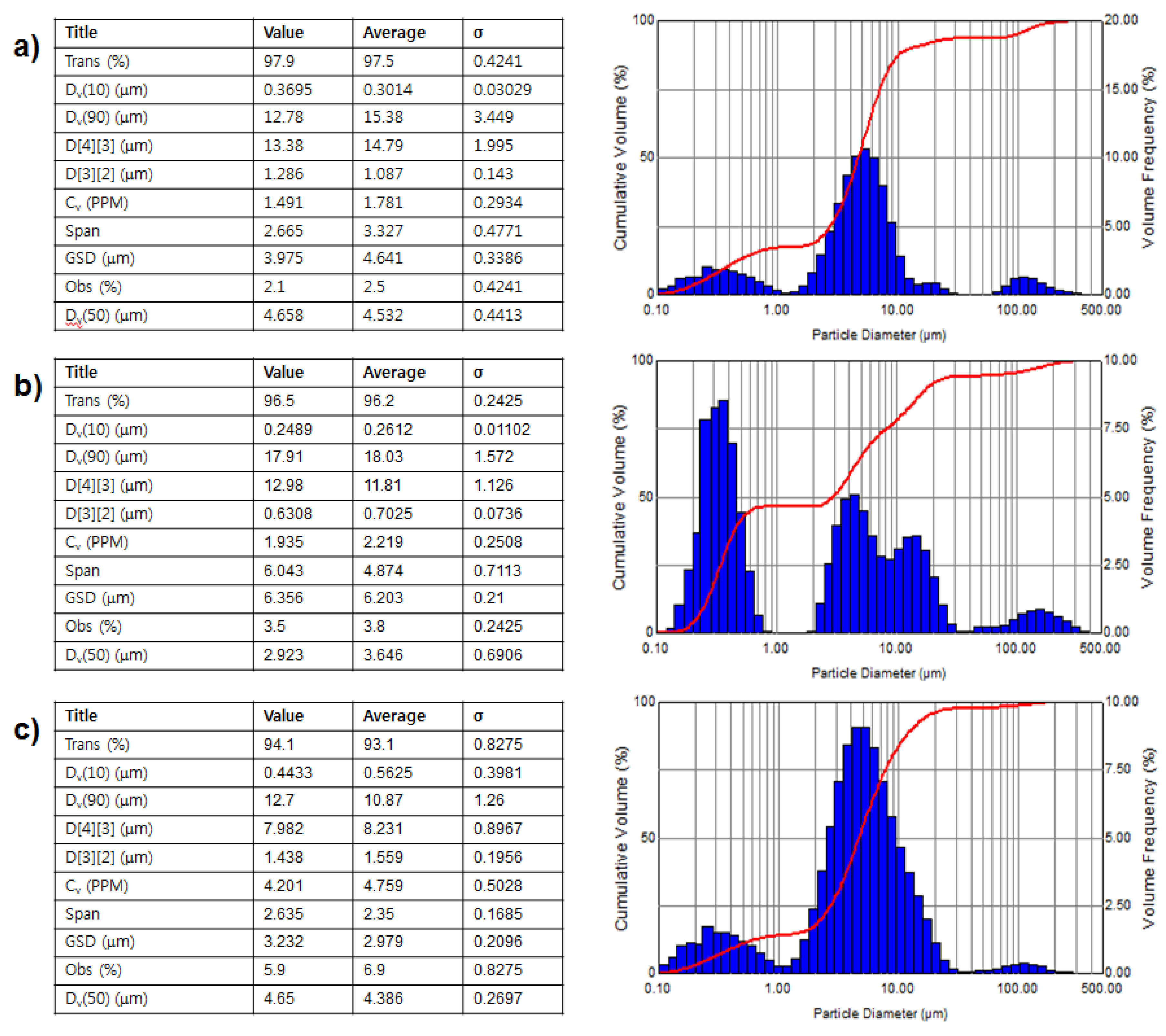
Figure 8 shows the characteristic diagrams of aerosol drops of various drug solutions. The droplets of all drugs were mostly distributed between 1 μm and 10 μm (
Figure 8). In the case of deionized (DI) water, the median value of the particle size distribution (Dv(50) value shown in
Figure 8) showed that the average particle size of the nebulized drug was 4.53 μm. In addition, the surface weighted mean (D[3][2] value shown in
Figure 8), which is sensitive to a small particle size, was 1.09 μm. This result indicated that it can be inferred that the droplet size distribution of the micro-nebulizer described in this research was finer and smaller than that of current and conventional devices. On the other hand, the Dv(50) value of amphetamine solution was 3.65 μm and the D[3][2] value was 0.70 μm. These results indicated that, in the case of the nebulized amphetamine solution, the average size of the particles, and that of small particles, was smaller than the particles of nebulized DI water. These differences may be caused by the formation of irregularly-aggregated amphetamine molecules at high concentrations of amphetamine. Generally, it is well known that organic drug molecules with amphiphilic properties participate in the formation of irregular aggregation at high concentrations. Therefore, the formed aggregates were expected to greatly affect the size shrinkage of drug droplets. Similar results were obtained for the levofloxacin solution. In the case of levofloxacin, the Dv(50) value wsas 4.39 μm and the D[3][2] value was 1.56 μm.

 and
and 