Review

Probing Ferroic States in Oxide Thin Films Using Optical Second Harmonic Generation

Department of Materials, ETH Zurich, Vladimir-Prelog-Weg 4, 8093 Zurich, Switzerland
*
Author to whom correspondence should be addressed.
Appl. Sci. 2018, 8(4), 570; https://doi.org/10.3390/app8040570
Submission received: 28 February 2018 / Revised: 27 March 2018 / Accepted: 3 April 2018 / Published: 6 April 2018
(This article belongs to the Section Materials Science and Engineering)

Abstract

:
Forthcoming low-energy consumption oxide electronics rely on the deterministic control of ferroelectric and multiferroic domain states at the nanoscale. In this review, we address the recent progress in the field of investigation of ferroic order in thin films and heterostructures, with a focus on non-invasive optical second harmonic generation (SHG). For more than 50 years, SHG has served as an established technique for probing ferroic order in bulk materials. Here, we will survey the specific new aspects introduced to SHG investigation of ferroelectrics and multiferroics by working with thin film structures. We show how SHG can probe complex ferroic domain patterns non-invasively and even if the lateral domain size is below the optical resolution limit or buried beneath an otherwise impenetrable cap layer. We emphasize the potential of SHG to distinguish contributions from individual (multi-) ferroic films or interfaces buried in a device or multilayer architecture. Special attention is given to monitoring switching events in buried ferroic domain- and domain-wall distributions by SHG, thus opening new avenues towards the determination of the domain dynamics. Another aspect studied by SHG is the role of strain. We will finally show that by integrating SHG into the ongoing thin film deposition process, we can monitor the emergence of ferroic order and properties in situ, while they emerge during growth. Our review closes with an outlook, emphasizing the present underrepresentation of ferroic switching dynamics in the study of ferroic oxide heterostructures.

Graphical Abstract

1. Introduction

Among the ferroic systems, ferroelectrics are subject to intense scrutiny by the scientific community due to their promising impact on current and future energy-efficient technologies [1,2,3,4]. The low-energy consuming electric field driving their polarization direction, and therefore their functionality, makes ferroelectrics of interest for novel device applications. In the drive for power-efficient oxide electronics, the recent development regarding the control of thin film ferroelectricity spans from the determination of critical thicknesses in the ultrathin regime [5,6] to ferroelectric domain engineering using epitaxial strain [7,8]. Since all ferroelectrics are piezoelectric, their range of applications can even be extended beyond charge-based memory devices to include mechanical device concepts such as stress sensors, etc. [2]. Furthermore, in the case of coexisting electric and magnetic orders in multiferroic thin film materials, new avenues toward increased data storage density can be realized [9,10,11]. A memory bit could indeed be stored independently in the magnetic and in the ferroelectric state. In addition, when the two ferroic orders are coupled, the magnetoelectric coupling can enable the implementation of energy-efficient, electrically writable magnetic memories [12,13,14,15].
Reviews on SHG and its potential for probing ferroic states in bulk crystals are available in the literature [16,17,18]. Here we place the emphasis on recent development in SHG for investigating ferroelectric and multiferroic thin films and heterostructures. Therefore, the first part of this review is devoted to ferroic domain design in thin layers and superlattices. In the following sections, we review the progress made in SHG as tool to access the properties and challenges posed by ferroelectric and multiferroic domains in thin film architectures. By its symmetry sensitivity and its non-invasive nature, SHG appears as a complementary tool to the traditional approach by scanning probe microscopy (SPM) and electron microscopy.

1.1. Ferroelectric Thin Films

While tremendous advances have been made in understanding ferroelectrics on their own, fundamental aspects of their behavior in the ultrathin regime or once inserted in multilayers or superlattice architectures are still under intense investigation [19,20,21]. The buildup of a ferroelectric polarization P in a material is accompanied by the accumulation of bound charges at its surfaces. As a result, the system hosts an internal field, induced by these bound charges, which is oppositely oriented to the polarization direction; see Figure 1. This depolarizing field D depends on the thickness of the ferroelectric layer and its electrostatic environment, such as the presence of metallic electrodes or the surrounding gas partial pressure and their respective charge screening efficiencies [22,23,24]. The role of the depolarizing field becomes critical in ultrathin ferroelectric single layers and in superlattices, where interface effects may become predominant [19,21,25,26]. As illustrated in Figure 1, a small change in film thickness and charge environment will have a drastic influence on the manifestation of a ferroelectric state and its domain configuration. For instance, in superlattices, polarization can be stabilized at ultra-low thickness [27,28] or a global enhancement of ferroelectricity can be achieved [29]. In a charge compensating environment, a single domain state is favored in a wide range of thicknesses; see Figure 1b. In the case of absent or incomplete charge screening, the presence of the depolarizing field will result in splitting of the single-domain state into a 180° multi-domain pattern, the formation of flux-closure domains or the emergence of ferroelectric vortices depending on the thickness and strain state considered; see Figure 1c.
In ferroelectric-based heterostructures, the intricate character of the interactions between polar and non-polar, metallic and non-metallic layers and the difficulty to access buried ferroelectric states renders the control of polarization challenging. Furthermore, probing the emergence of ferroelectricity or the domain state in thin films as function of thickness, strain and temperature is hindered by the lack of contactless probing techniques. Leakage currents [30] in the ultrathin regime and at elevated temperatures prevent the understanding of ferroelectricity in the low thickness regime.
On the structural level, pioneering theory and experimental work dealing with ferroelectric thin film behavior under epitaxial stress evidenced the potential of epitaxial strain as a new degree of freedom for controlling the ferroelectric state in single layers [7]. In situ oxide growth diagnostic tools such as reflection high energy electron diffraction (RHEED) [31] together with the development of single crystal substrate manufacture, allow precise engineering of the strain state in high-quality thin films. Using a combination of phase field simulations and experimental techniques, it was further shown that strain can be used to tune the ferroelectric polarization [32], enhance the Curie temperature [33,34] and induce a selectivity to specific ferroelectric switching events [35]. Epitaxial strain can also be used to induce a ferroic state. For instance, ferromagnetism was strain induced in orthorhombic LuMnO3 thin films [36] while a polar state was stabilized in tensile strained SrMnO3 thin films [37]. However, experimental evidence of such a control remains inaccessible in multilayer architectures due to the increasing role of interfaces and the lack of a direct probe of ferroelectricity in a buried configuration.

1.2. Multiferroicity in Thin Films

The so called multiferroic materials are defined in the single-phase case by the simultaneous presence of two or more ferroic orders. Hence, a ferroelectric state can under certain conditions coexist with magnetic order [38]. Multiferroic materials were first investigated in the late 1950s and were the subject of an intense revival when the scientific community became aware of their high potential towards low-energy consuming electronics [39,40].
Taking advantage of the progress in thin film deposition techniques, the early motivation for multiferroic thin-film growth resided in reproducing multiferroic bulk properties in reduced dimensions to lower the external switching field requirements for applications. The pioneering results in the field deal with the growth of multiferroic magnetoelectric BiFeO3 (BFO) thin films [41] and multiferroic hexagonal manganite thin films [42,43]. In both cases, the coexistence of magnetic ordering and ferroelectric polarization was shown. The multiferroic thin film research field subsequently evolved and led to the development of strain engineering of multiferroic properties [44,45,46] and the design of artificial multiferroic heterostructures where multiferroicity is introduced as a product effect by the combination of different ferroic constituents [44].
Following the recent development of the electrical control of magnetization using multiferroics [47], the development of experimental techniques giving access to multiferroic and magnetoelectric domain configurations has become a priority for the scientific community.

1.3. Ferroic Domain Engineering in Single Layers and Superlattices

The combination of epitaxial strain, surface termination and electrostatics in ferroic thin films and heterostructures can be used for domain engineering. Deterministic control of the domain formation process toward the design of complex ferroic states in three dimensions is a necessary means to realize next-generation oxide-based devices [48,49,50,51].
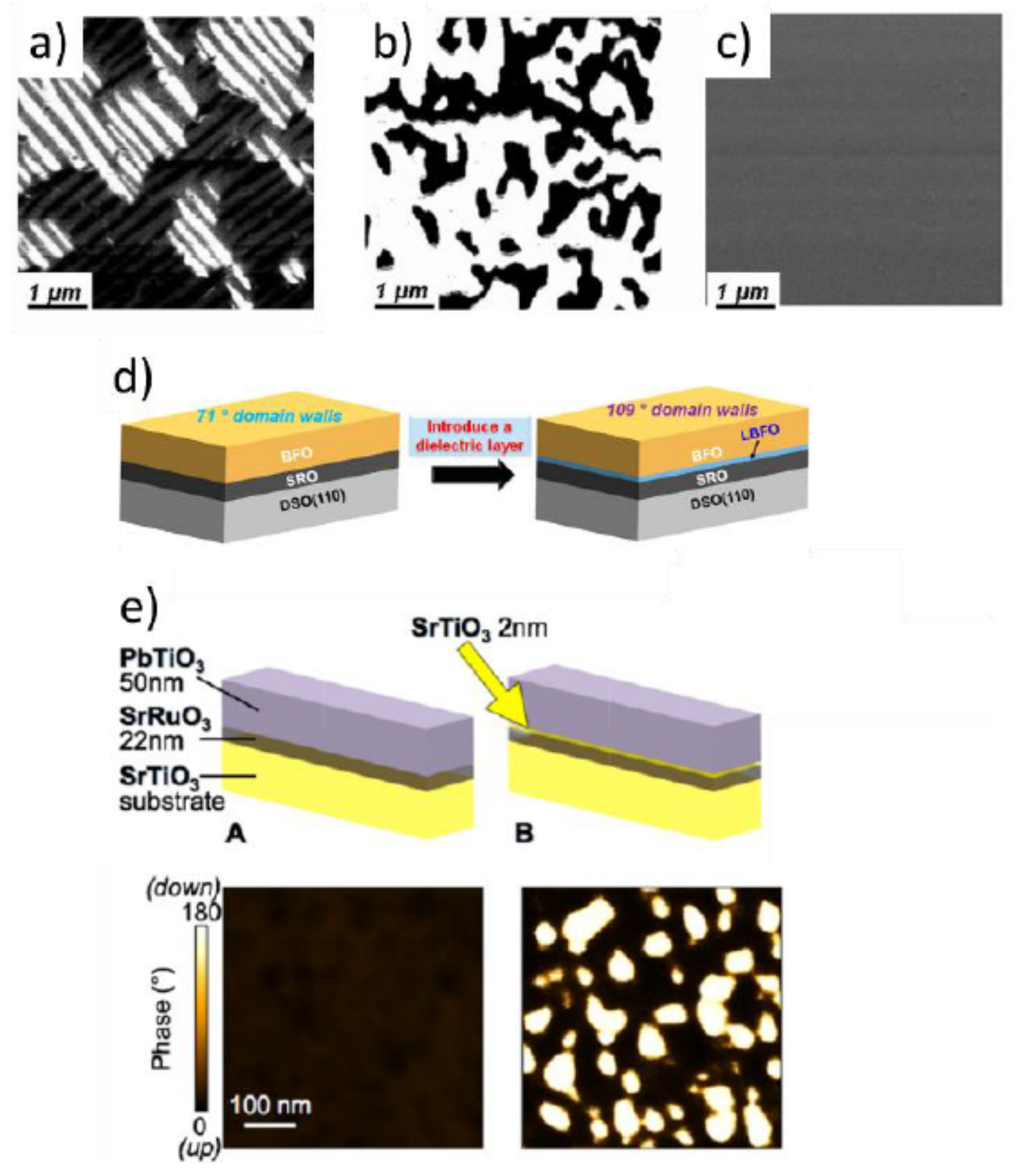
One instructive example of strain engineering the ferroic domain structure in single layers is the case of multiferroic BFO thin films. In this system, Chu and coworkers [52] demonstrated the ability to modify the ferroelectric domain state by using relevant substrate orientations and surface states. Starting from the eight symmetry-allowed polar axes along the <111> crystallographic directions of the pseudo-cubic unit cell, the number of as-grown ferroelectric variants could be tuned to either a four ferroelectric variants or a two ferroelectric variants configuration, when grown on the cubic perovskite (001) or (110) orientation of SrTiO3 (STO) substrates, respectively. A single domain state could be achieved when using (111) oriented STO (see Figure 2a–c). Further tuning of the domain architecture was achieved with the use of scandate substrates [53]. DyScO3 (DSO) crystallizes in the orthorhombic space group with a pseudo-cubic unit cell exhibiting a slight anisotropy between the in-plane lattice parameters [54]. This results in an in-plane anisotropic strain which can further lift the degeneracy of polar domains of perovskite ferroelectrics [53]. Scandate substrates have also been used to induce multiferroicity in STO thin films [55,56] and EuTiO3 layers [57,58].
Beyond epitaxial strain considerations alone, the macroscopic out-of-plane polarization orientation and the domain state in thin film ferroelectrics also drastically depend on their electrostatic environment [59] and the surface termination of the substrate [60,61]. Screening conditions affect the stability of domain walls and are a key parameter in the control of complex domain structures. By inserting a dielectric layer between the ferroelectric thin film and the metallic buffer, the 109° stripe domain state could be favored in BFO [62] and 180° domains were stabilized in PbTiO3 (PTO) [63,64]; see Figure 2d,e, respectively.
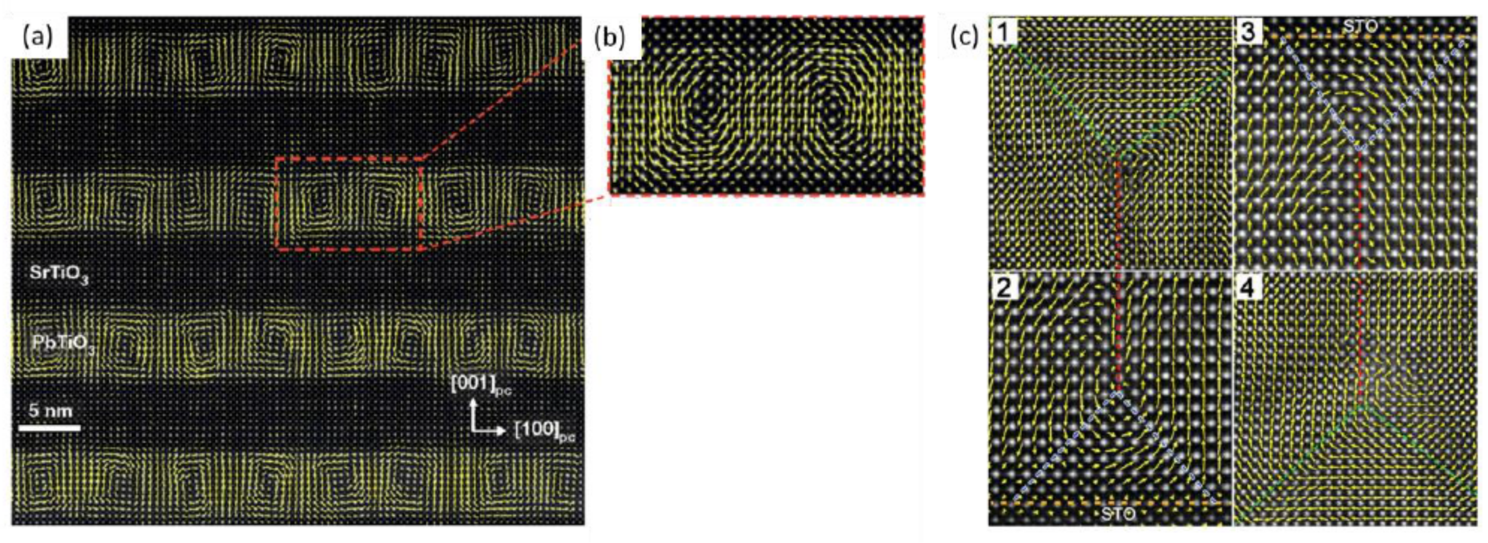
By tuning ferroelectric layer thicknesses and controlling the nature of the charge screening environment in heterostructures and superlattices, it is possible to engineer the ferroelectric domain architecture in three dimensions [61,65]. A prominent example is the formation of ferroelectric vortex domains in PTO/STO superlattices, as shown in Figure 3a,b [48] or the stabilization of flux-closure domain patterns in PTO single layers inserted between two STO dielectric layers; see Figure 3c [65].
The direct observation of three-dimensional ferroelectric and multiferroic domain architectures is however not trivial. The conventional SPM technique usually requires the contact with the functional layer and is inherently surface sensitive, therefore lacking the demanded depth analysis of the structure. A particular challenge arises in probing domain structures in a multilayer configuration where the ferroic layers are capped by an impenetrable layer. In active devices, the functional layer is often capped by a conducting electrode which limits the piezoresponse force analysis to the out-of-plane polarization component [4,66,67].

1.4. Current Challenges in Probing Ferroic Domains in Thin Films

Currently, state-of-the-art observation of ferroelectric domain distribution in the volume is provided primarily by scanning transmission electron microscopy (STEM). This imaging technique allows spatial mapping of local polarization but remains a destructive analysis and is highly dependent on the sample preparation. Other experimental techniques such as synchrotron X-ray diffraction-based techniques [21,26,68] can identify polarization orientation and additional periodicities originating from domain formation, but the involvement of large-scale facilities renders their generalization towards day-to-day operation impractical. For a complete understanding of the role of epitaxial strain and electrostatics at the created oxide interface, noninvasive access to the polarization state is essential.
When it comes to probing several ferroic orders simultaneously, as is desirable in multiferroics, additional experimental constraints need to be considered. Most ferroelectric multiferroic materials exhibit antiferromagnetic ordering and therefore do not possess a net magnetic moment. Hence, antiferromagnetic domain visualization remains challenging. An efficient way to observe antiferromagnetic domains is using the principle of ferroic domain imprint transfer [69,70,71,72,73]. A thin ferromagnetic layer is deposited in direct contact with the multiferroic layer. The interfacial exchange coupling with the underlying antiferromagnetic layer results in the formation of ferromagnetic domains in the ferromagnetic film that can be resolved using scanning electron microscopy with polarization analysis (SEMPA) [72] as shown in Figure 4a,b, or magnetic force microscopy (MFM) [72,74]. The underlying ferroelectric domain state is however no longer reachable using conventional scanning probe experiments, i.e., piezoresponse force microscopy (PFM), after the ferromagnet has been deposited.
Recently, a single spin magnetometer technique was developed based on point-like impurity nitrogen-vacancy (NV) defect in diamond [75,76,77]. This scanning-probe technique was used to spatially resolve the local magnetic order in multiferroic antiferromagnetic BFO thin films [78]. A periodic modulation in the magnetic response corresponding to a spin cycloid was measured within a single ferroelectric domain; see Figure 4c,d. This spatially resolved characterization of antiferromagnetic domains does not prevent the subsequent ferroelectric analysis in the same surface area and signifies important progress towards the analysis of multiferroic domains.
However, the direct access to multiferroic domains in buried configurations, i.e., in a device architecture or in a superlattice, remains impossible using the scanning probe approach.

2. Optical Second Harmonic Generation for Investigation of Ferroic Materials

Optical second harmonic generation (SHG) offers a complementary approach to SPM analysis in ferroic analysis. It is non-invasive, contact-free and can probe the entire volume of a thin film structure including buried layers in heterostructures.

2.1. SHG in Bulk Ferroic Systems

Optical SHG refers to the frequency doubling of a light wave. The SHG emission in a crystal depends on its point group symmetry and SHG is therefore in general sensitive to any point symmetry violation in the material. Since the emergence of ferroic order is intimately linked to a lowering of the crystal point-group symmetry, such ordered states are aptly probed with SHG [16,17,18,79]. More importantly, this technique can be used to probe coexisting ferroic states, as in multiferroics. The source term for SHG is described macroscopically by the tensor Equation (1).
P i ( 2 ω ) = ε 0 χ i j k E j ( ω ) E k ( ω )
The tensor components χijk belong to the third-rank second-order susceptibility tensor χ(2), parameterizing the non-linear light-matter interaction. The indices i, j and k are defined with respect to the crystallographic axes of the crystal x, y and z and denote the directions of the respective oscillating fields. E is the electric field component of the incident light at frequency ω, and P is the polarization at frequency 2ω induced inside the material. This induced polarization acts as a source of an emitted, frequency-doubled, light wave with intensity ISHG ∝ |P (2ω)|2. The point-group symmetry of a compound determines its set of tensor components χijk ≠ 0. The allowed tensor components for each symmetry group can be found tabulated in literature [80].
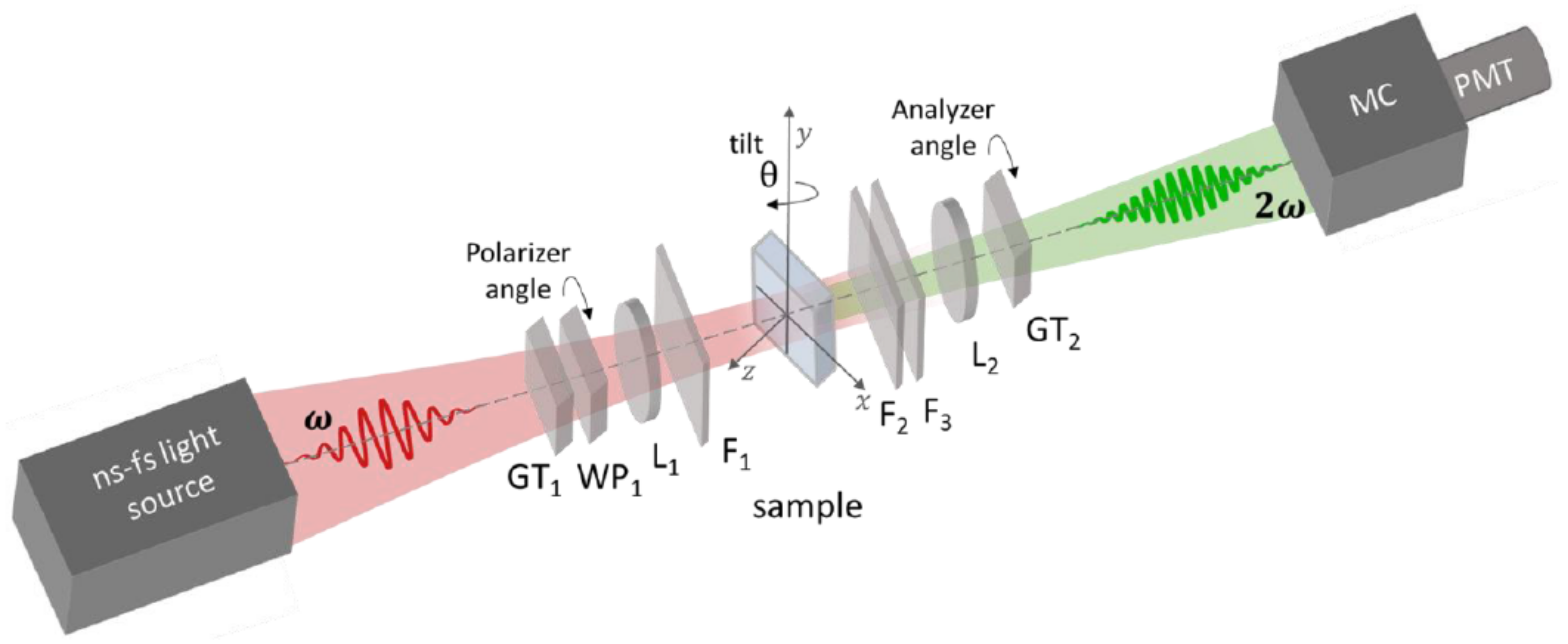
Experimentally, specific χijk components can be accessed through a careful choice of incident and detected light polarization [16,17,18]. The spectral dependence of the χ(2) tensor can be determined using a tunable wavelength light source and can provide in-depth information on specific electronic transitions and optimal SHG response [81,82]. A schematic of a basic SHG set up in transmission is given in Figure 5. The direction of polarization of the probe beam is defined by the polarizer angle, and the polarization direction of the detected SHG light is projected along the analyzer angle, as indicated in Figure 5. Because the second harmonic light is spectrally distinct from the fundamental light, the SHG frequency can be simply monitored separately from the probe beam intensity and is as such a background-free characterization technique.
In the specific case of ferroelectrics, inversion symmetry is broken by a polar distortion, allowing non-zero χijk components. To characterize the polar distortion along a certain crystallographic direction, and to be able to discriminate between excited tensor components, one can fix the detected polarization direction of the second harmonic light, i.e., the analyzer angle, while rotating the polarization of the probe beam. Here, we refer to such characterization as polarizer measurements. In general, the polar axis of the investigated sample can point along an unknown direction. This orientation can be accessed by fixing both the incoming and detected light polarization while rotating the sample along the azimuthal angle defined by the sample surface.
Equivalently, this in-plane polar anisotropy measurement can also be performed with a simultaneous rotation of the polarization of both probing and detected light while keeping the sample position fixed. Because the SHG technique only probes polar distortions projected on a plane perpendicular to the k-vector of the incident light wave, it may be necessary to introduce a tilt of the angle of incidence (denoted by θ in Figure 5). This changes the direction of the k-vector with respect to the crystal and provides access to certain domain orientations.
SHG is a well-established technique to non-invasively probe bulk materials where domain dimensions are expected to be larger than the spatial resolution limit (about a micrometer). Indeed, it has been used to image ferroelectric domains [83], antiferromagnetic domains [84,85] and more recently multiferroic domains in bulk systems [86,87], as can be seen in Figure 6.
Local symmetry mapping is performed by selectively coupling to SHG tensor components which are domain orientation dependent. Spatially-resolved SHG, using a charge-coupled device (CCD) camera detection system, then shows domains with 90° relative orientation in different brightness; see Figure 6a. Since each phase of a material corresponds to an individual set of non-linear tensor components, phase coexistence can also be mapped using optical SHG. Figure 6b demonstrates the presence of orthorhombic twins in a tetragonal BaTiO3 (BTO) crystal. Furthermore, domains with opposite order parameter, i.e., ±P in the ferroelectric case, emit SHG light waves with a relative 180° phase shift. Superimposing these light waves with a reference light, one can achieve domain contrast and observe oppositely oriented domains with different brightness [79,88].
Moreover, the emergence of SHG signal as a function of temperature is a powerful method to identify the critical temperature of phase transitions in the ferroic compound under investigation. This is particularly useful when standard characterization techniques are unable to characterize the emergence of the ferroic order [86].
For exemplifying the relation that connects a particular pattern of ferroic domains to a specific polarization-dependent SHG signal we consider the case of a single-domain ferroelectric state in the multiferroic model system BFO. The point symmetry of ferroelectric BFO allows a set of independent non-zero SHG susceptibilities. These are described as complex values so that they possess an amplitude χijk and a relative phase Ψijk. The resulting ferroelectric SHG signal is then given by [88]:
| P i ( 2 ω ) | 2 | j , k χ i j k e i Ψ i j k E j ( 2 ω ) E k ( 2 ω ) | 2
With z as surface normal, we find χxxx, χxxy, χxyy, χyyy, χyyx, χyxx, χxzz, χyzz, χzzx, χzzy as non-zero independent components for BFO (and accordingly for Ψijk) in accordance with its point symmetry group m. The effective polarization components of the SHG wave are given by
P x ( 2 ω )   χ x x x e i Ψ x x x cos 2 θ sin 2 φ + 2 χ x x y e i Ψ x x y cos θ cos φ sin φ + χ x y y e i Ψ x y y cos 2 φ + χ x z z e i Ψ x z z sin 2 θ sin 2 φ
P y ( 2 ω )   χ y y y e i Ψ y y y cos 2 φ + 2 χ y y x e i Ψ y y x cos θ cos φ sin φ + χ y x x e i Ψ y x x cos 2 θ sin 2 φ + χ y z z e i Ψ y z z sin 2 θ sin 2 φ
P z ( 2 ω )   2 χ z z x e i Ψ z z x cos θ sin θ sin 2 φ + 2 χ z z y e i Ψ z z y sin θ cos φ sin φ
Here, θ is the tilting angle, defined as the angle between the surface normal of the film and the k-vector of the incident light (θ = 0° corresponds to normal incidence). Furthermore, φ is the angle between the polarization of the linearly polarized incoming light and the y-axis; see Figure 5. Based on Equations (3)–(5), measurement of the polarization dependence of the SHG signal hence reveals the orientation of the ferroelectric polarization. In the general case, additional aspects increase the complexity of Equations (3)–(5). For example, in the case of a multidomain pattern, the spontaneous polarization of the single domain is either replaced by the net polarization of the domain pattern or the respective SHG waves associated to each contributing domain state are added up to reveal the total SHG yield of the domain pattern [88]. Furthermore, surface SHG contributions and Fresnel coefficients in the beam propagation [89] may have to be considered.

2.2. Special Considerations in Thin Film SHG Experiments

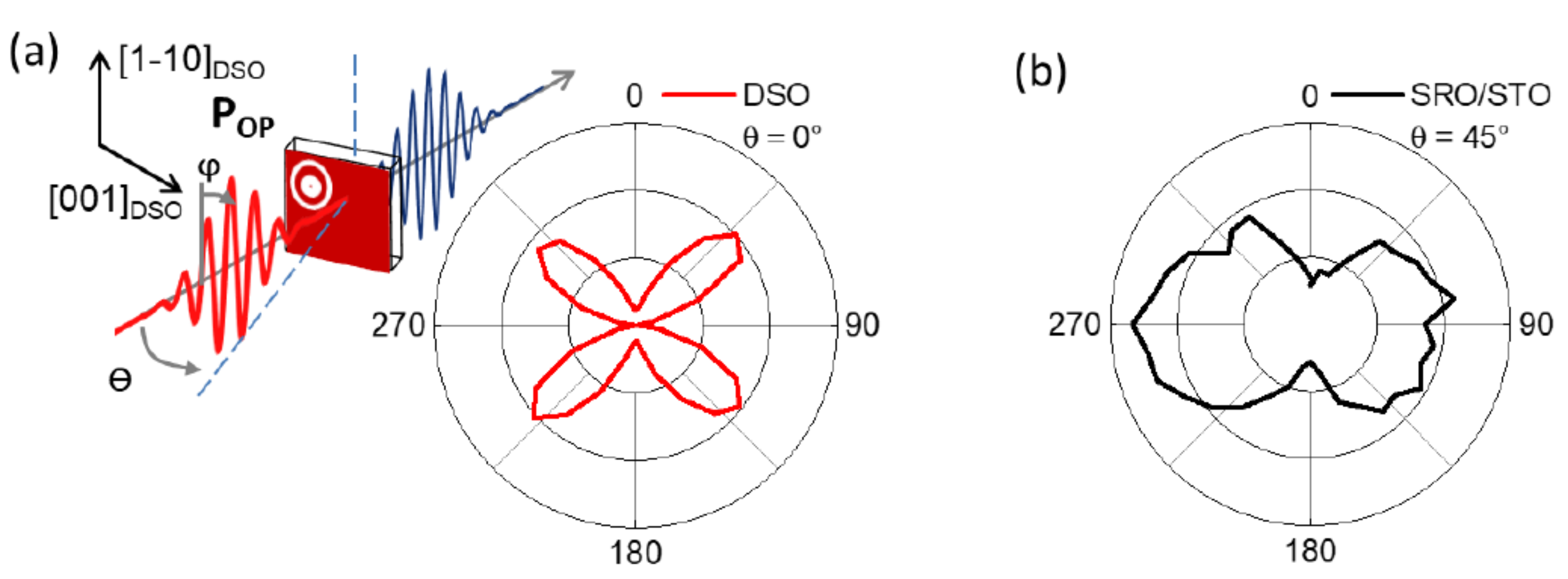
Nonexistent in bulk systems, the presence of a substrate in the thin film system can have a significant influence on the SHG response. The substrate material may itself produce a non-zero SHG signal (see Figure 7) [88] that can interfere with the thin film response. Additionally, due to the breaking of inversion symmetry at surfaces and interfaces, there is often a surface contribution to the SHG response [86,88,90]. These additional components should be considered in thin film experiments as they may be a dominant part of the SHG signal in reduced volume conditions of the ferroic layer.
On the other hand, such parasitic SHG provides a reference light wave which can be used in interference experiments to achieve domain contrast in imaging experiments [79,86,88]. The substrate-induced SHG response in the case of a DSO substrate measured in transmission is shown in Figure 7a. The surface-related SHG signal emerging from a centrosymmetric SrRuO3 (SRO) metallic oxide measured in reflection is shown in Figure 7b.
For full access to the possible orientations of polar axes in a thin film material, it is often desirable to generate SHG in transmission where surface contributions can be avoided in normal incidence configuration. However, while thin films of only a few tens of nanometers in thickness have negligible absorption throughout the visible and near-infrared spectrum, the absorption spectrum and possible birefringence effects of some substrates might affect the thin film SHG detection [16,80]. To minimize the substrate SHG contributions in thin film measurements, it may be advantageous to use an experimental setup in reflection geometry. There is therefore no standard SHG setup for thin films analysis and the balance between substrate, surface, and thin film contribution must be optimized in each measurement.
Finally, in contrast to many bulk systems, the expected domain sizes in thin films are usually below the optical SHG resolution limit. While certain sub-resolution features can be detected using SHG under the proper conditions, the efficiency to probe a ferroelectric state in thin films with SHG truly comes into its own when single domain or macroscopically-ordered domain systems are selected, i.e., when a macroscopic net polarization is present.

3. Probing Ferroic States in Thin Films Using SHG

In the following sections we review the major areas of application of SHG for probing ferroic states in thin film single layers and heterostructures. Results dealing with prototypical ferroelectric PbZr0.2Ti0.8O3 (PZT) and multiferroic BFO materials are highlighted.

3.1. Optical Second Harmonic in Domain Engineered Ferroic Thin Films

The SHG technique is a powerful technique for the analysis of polar states in thin films possessing a net ferroelectric polarization, i.e., in a single domain state or in domain-engineered systems [88]. Uniaxial tetragonal ferroelectric PbZr0.2Ti0.8O3 (PZT), the most technologically relevant ferroelectric compound, shows a thickness-dependent domain distribution [91]. A fully strained film can exhibit a single domain state with a polar axis pointing out of plane, along the long tetragonal c-axis. Above a threshold thickness (of about 60 nm in the case of PZT grown on LaAlO3 substrates [91]), strain relaxation will induce a coexistence of nanosized in-plane oriented domains, i.e., a-domains with a polarization pointing along the in-plane oriented long axis, together with the out-of-plane c-domains [92,93]. The a-domains nucleate from either the top or the lower interfaces and their distribution in the volume can have major implication on the ferroelectric switching dynamics and thus on the targeted applications [94,95,96]. It is, however, non-trivial to access the ferroelectric domain distribution in the thin film volume when using scanning probe techniques due to their limited depth sensitivity.
As discussed in the previous section, the optical SHG technique only probes polar distortions projected on a plane perpendicular to the k-vector of the incoming light wave [16,17,18]. It is, therefore, possible to disentangle the contribution of a- and c-domains by changing the orientation of the ferroelectric polar axis with respect to the incident light beam [97].
The single-domain state of a thin film (15 nm thick) with a polarization pointing out of plane can be confirmed by PFM as shown in Figure 8a. For a fully c-oriented tetragonal film with point group 4mm, three independent χijk components (χzzz, χzxx and χxzx) are non-zero [80,97]. At normal incidence (θ = 0°), no second harmonic response is expected since the out-of-plane directed ferroelectric polarization then points along the k-vector. When tilting the ferroelectric system with respect to the incident light beam, the increment of the incidence angle will result in an increase of the associated SHG signal as shown in Figure 8b. The specific light polarization configuration is described in the inset of Figure 8b. The angular dependence of the SHG light in the polarizer measurement identifies the projection of the polar distortion to be along the direction of the double-lobe shape, as seen in Figure 8c. Here, the [001]DSO direction of the substrate is orthogonal to the tilt-axis ([1–10]DSO) and represents the projection of an out-of-plane polarization.
For a thicker layer, the epitaxial strain relaxation promotes the growth of nanosized stripe-domains with an in-plane polarization orientation, as evidenced by the PFM scan performed on the 75 nm thick film in Figure 8d. Here, specific light polarization configurations allow discriminating between the in-plane (in black) and the out-of-plane (in blue) contributions to the nonlinear optical response, as shown in Figure 8e. It is worth emphasizing that the SHG intensity associated with the in-plane domains is non-vanishing at normal incidence (θ = 0°), where no contribution is expected from c-axis (out-of-plane) domains. The polarizer measurement shown in Figure 8f highlights the presence of a macroscopic in-plane polarization directed along [1–10]DSO. Note that in the presence of a complex sub-optical-resolution domain architecture where two sets of orthogonally oriented a-domains coexist [93], the SHG signal will not yield the spontaneous polarization of each domain but rather reflect the direction of the macroscopic in-plane net polarization resulting from the sum of all the a-domain contributions. In the present case, this corresponds to a 45° rotation of the polar axis shown in Figure 8f, as further discussed below for the case of BFO films. SHG is therefore sensitive to ferroelectric domains smaller than the optical resolution and the presence of a-domains throughout the volume of the film can be identified optically [97]. We note however that complementary scanning transmission electron microscopy is necessary to address specific domain morphologies throughout the film thickness [97].
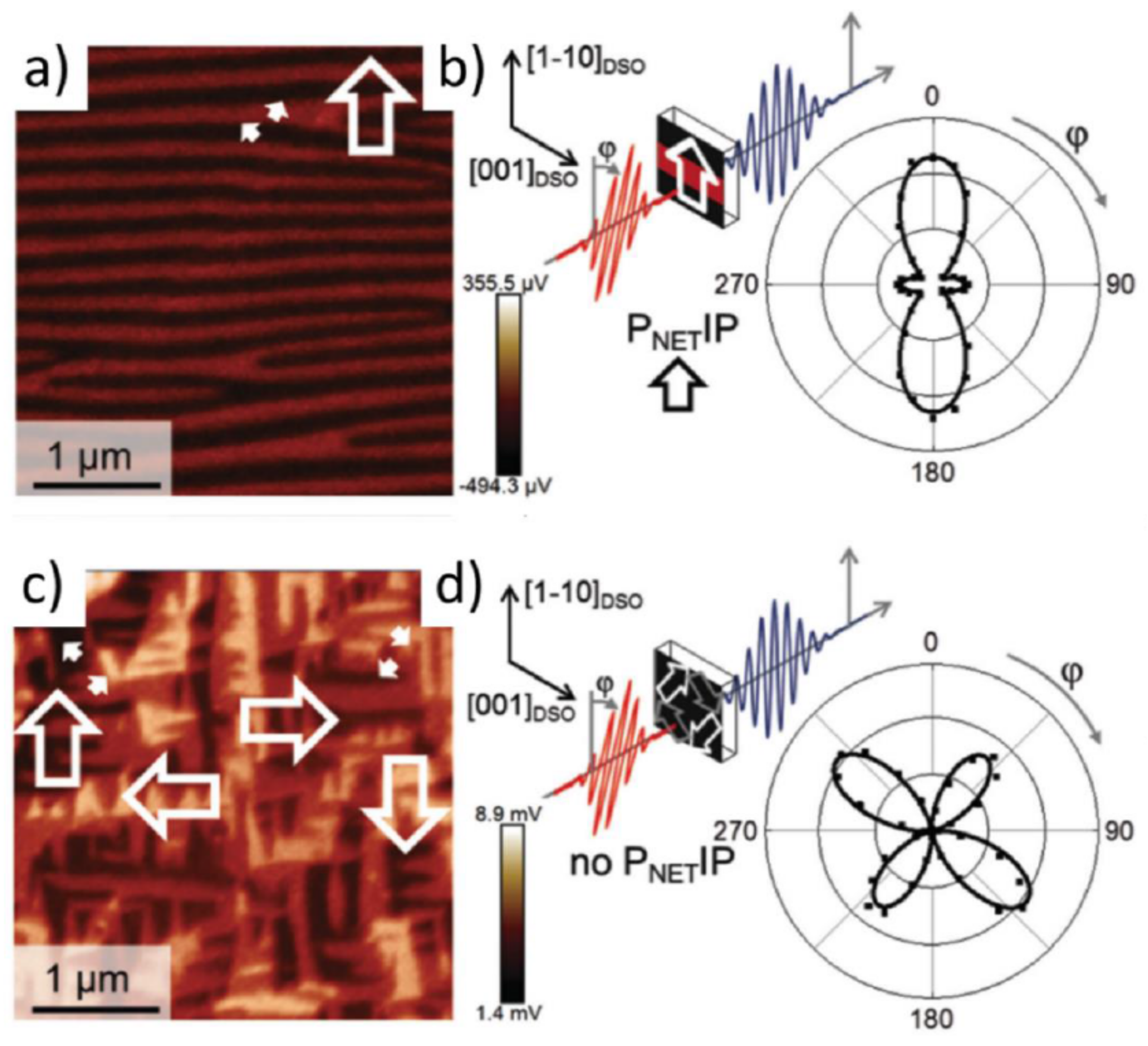
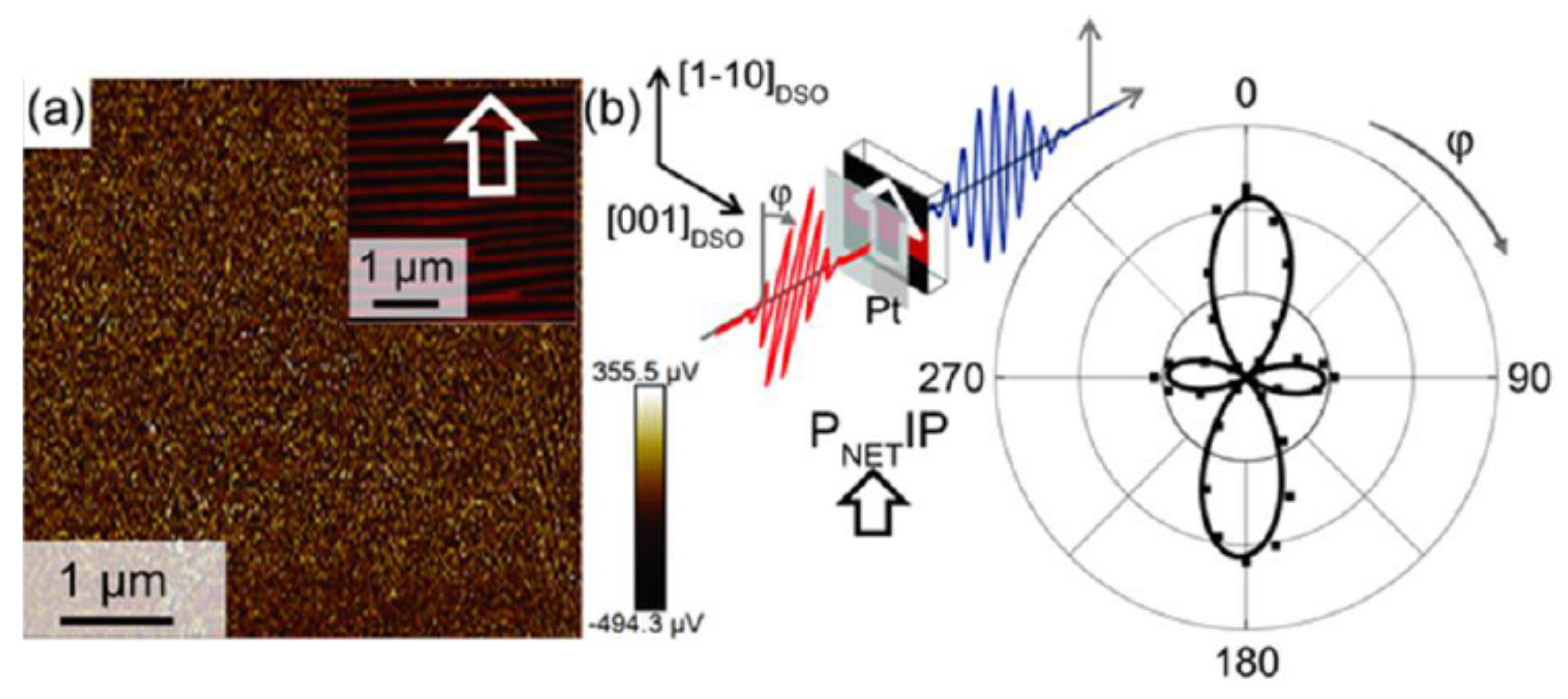
The correspondence between the angular dependence of SHG and the orientation of the polar axis can be exploited further to identify the direction of a net polarization when more complex domain structures are considered [88]. For example, domain-engineered multiferroic BFO films subject to an in-plane anisotropic strain present two ferroelectric variants arranged in a stripe pattern (Figure 9a) [88]. The in-plane projections of the polarization in adjacent domains differ by 90° as highlighted by the small white arrows in the PFM scan in Figure 9a. This produces an average net in-plane polarization orthogonal to the domain wall elongation (indicated by the large white arrow in Figure 9a). The angular dependence of the SHG light therefore manifests as a two-fold shape oriented along the macroscopic polar axis direction as shown in Figure 9b.
In the absence of such in-plane anisotropy, four equivalent ferroelectric variants nucleate, characterized by the absence of an average macroscopic in-plane polarization (Figure 9c). In this case, the associated SHG signal does not depend on the sample orientation; see Figure 9d.
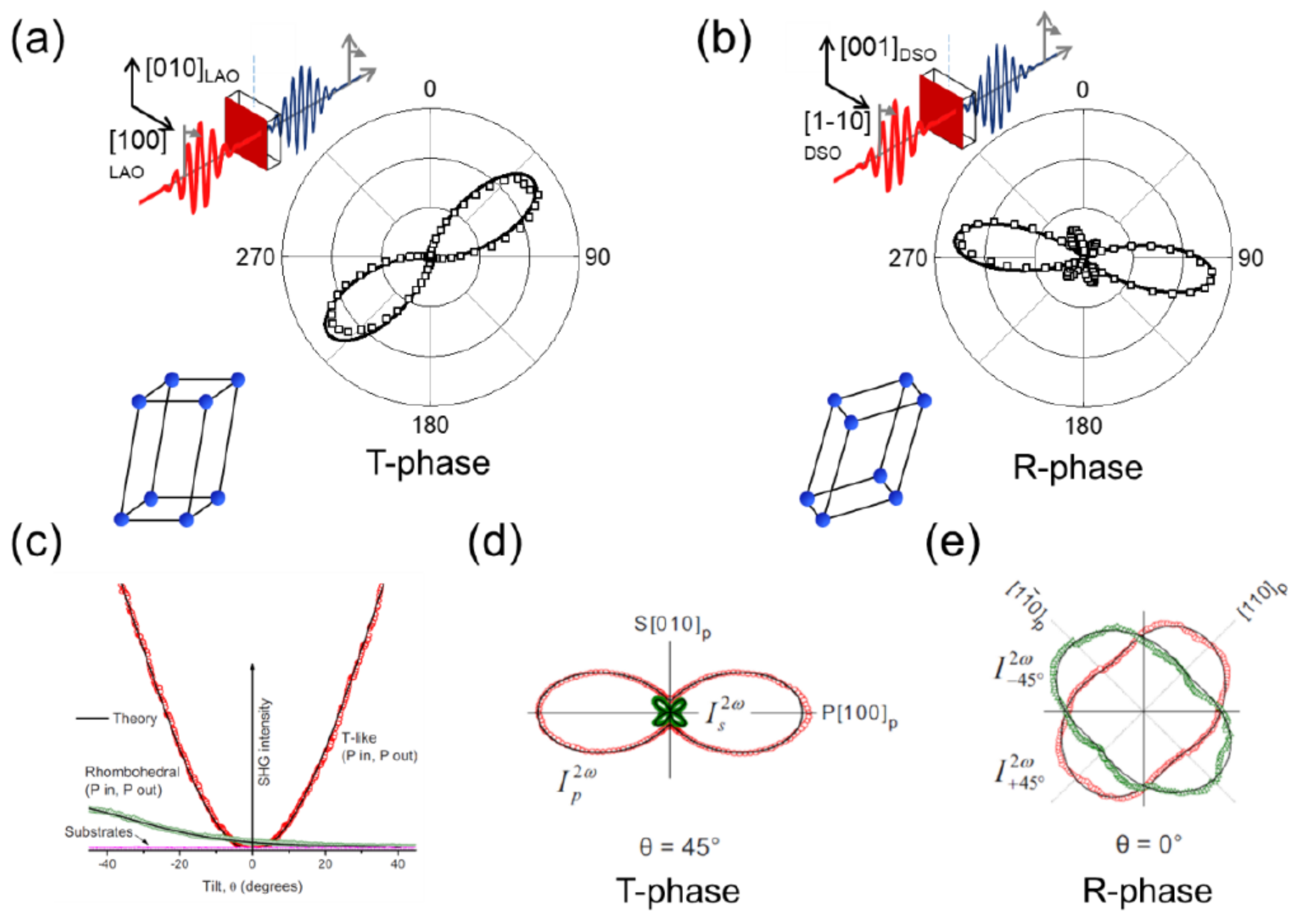
SHG can also detect subtle structural changes such as strain dependent monoclinic distortions in epitaxial films. In particular, large compressive strains (>4.5%) in BFO films induce a tetragonal-like distortion favoring the emergence of a pseudo-tetragonal phase, i.e., BFO T-phase, while smaller compressive strains are associated with a rhombohedral-like distortion stabilizing the pseudo-rhombohedral phase, i.e., BFO R-phase [98,99]. These two phases possess the same monoclinic point group m but are characterized by a rotation of the in-plane polarization of 45° at the unit-cell level [100]. With SHG, these two phases can be simply distinguished by observing the direction of the double-sided lobe [88,101,102,103] as shown in Figure 10a,b. Note that the orientation of the polar axis is inclined by a few degrees with respect to the crystallographic axes due to the monoclinic distortion.
The R- and T-phases can also coexist in the same thin film system [98]. At the strain-driven morphotropic phase boundary, exotic conducting states and enhanced piezoelectric coefficients have been observed [104,105]. The SHG contributions associated with the two phases have different relative intensities as a function of the angle of incidence [101,102,103,106] as shown in Figure 10c. The pseudo-tetragonal phase (in red) has a symmetric behavior similar to a genuine tetragonal structure (cf. Figure 8b), while the SHG response of the R-phase (in green) reflects its polarization anisotropy. These distinct behaviors allow associating the nonlinear optical output at different incidence angles to the two ferroelectric phases, as shown in Figure 10d,e. In particular, a measurement at θ = 45° will be sensitive to the T-phase, while at normal incidence the SHG output is associated to the R-phase.
For a fixed substrate, i.e., strain state, the strain relaxation with increasing thickness will modify the relative ratio of BFO T- and R-phases. This structural evolution results in a symmetry change for BFO films at various thicknesses that can be studied with SHG [107]. In ultrathin films grown in a compressive strain state using Nb-doped STO as substrate, a four-fold rotational symmetry associated with the absence of in-plane anisotropy is attributed to the T-phase [107] as shown in Figure 11a. Around 100 nm, there is a transition regime where both phases coexist, while at 180 nm the polar axis of the R-phase is fully developed as observed in Figure 11b,c.

3.2. Imaging of Ferroic Switching Events

Optical SHG polarizer and anisotropy measurements probe the net polarization state of thin films in various domain configuration and phases. To visualize domains, domain walls and electric field induced switching events, the symmetry investigation can be combined with spatial resolution when performing SHG imaging.
Understanding the dynamics and switching mechanisms of ferroic switching events is the first step towards a deterministic control over the targeted functionality. While ferroelectric switching events can be probed at the nanoscale using a combination of STEM and PFM [95,96,97], complex switching events in magnetoelectric multiferroic compounds require the ability to map several coexisting order parameters at the single domain scale. In BFO thin films, the electric-field-induced change in the antiferromagnetic domain configuration has been demonstrated [108,109] at the scale of the ferroelectric domains. In Figure 12a,b, the local change of magnetic order after voltage application is shown using a combination of PFM and photoemission electron microscopy (PEEM) [108]. This seminal work established the one-to-one coupling between the ferroelectric domain architecture and the corresponding antiferromagnetic domains. The electric field control over this domain correlation led to the deterministic observation of electric field induced magnetization reversal in BFO-based heterostructure at room temperature [11,12,13,14,110].
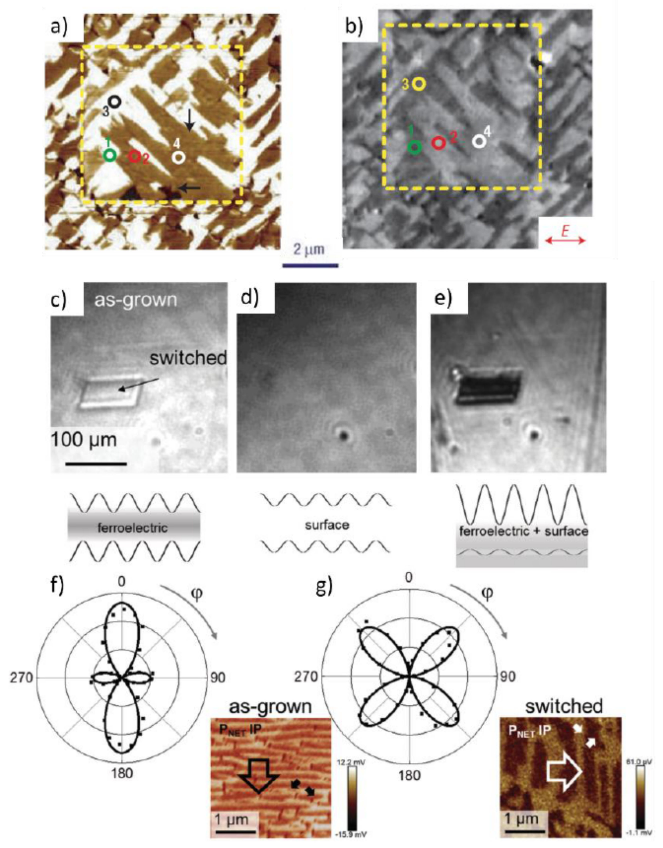
Using spatially-resolved SHG, the respective domain structure of each ferroic order and their mutual coupling can be non-invasively probed. As mentioned previously, the as-grown domain architecture in ferroic thin films is typically well below the optical resolution limit (see Figure 12). On the other hand, using scanning probe techniques, it is possible to electrically write macroscopic single domains that are large enough for SHG imaging. Taking advantage of interference effects between oppositely polarized domains and surface contributions [88], one can selectively resolve either the voltage induced domain walls or domains; see Figure 12c–e. Starting from an as-grown ordered ferroelectric domain pattern, SHG imaging together with symmetry component analysis can distinguish between different types of scanning tip-induced switching events [88]. Therefore, specific switching events induced by the trailing field (originating from the lateral movement of the tip during the scan) [111,112] can be optically probed, as shown in Figure 12f,g.
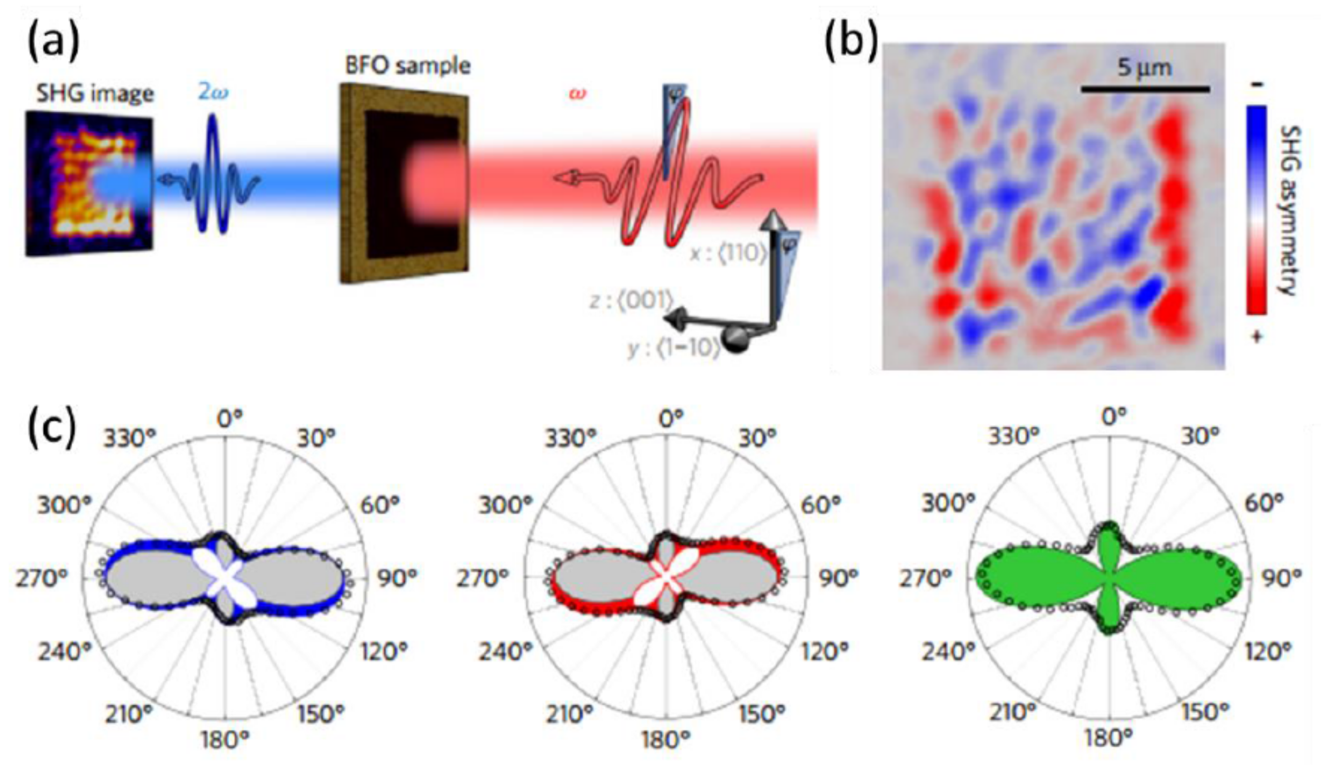
Furthermore, the simultaneous evolution of several ferroic orders upon application of external fields can also be visualized using spatially resolved SHG [113]. By symmetry component analysis of the local SHG response, contributions from both ferroelectric domains and antiferromagnetic domain variants were deconvoluted in BFO thin films (Figure 13). The individual symmetry components were isolated using spatially resolved polarizer measurements. The anisotropy of the light polarimetry distribution was identified and correlated to the presence of different antiferromagnetic domain variants, superimposed on the ferroelectric response; see Figure 13b. Comparing the spatially resolved SHG response of the domain structure before and after application of a scanning probe-tip induced external electric field, it could be observed that the switching of the ferroelectric polarization was accompanied by a change in the antiferromagnetic domain state [113]. This optical ferroic domain-mapping capacity demonstrated in the case of BFO thin films opens new avenues toward the determination of magnetoelectric switching dynamics in multiferroic-based heterostructures.
It has to be emphasized here, that the polarization orientation in thin films can be probed with SHG even when the layer is capped with a top electrode [88]. Figure 14 shows the PFM and SHG response of a BFO thin film capped with 4 nm Pt. While no in-plane PFM domain contrast is observed, the polarizer SHG measurement can identify the direction of the macroscopic polar axis of the buried BFO layer (see Figure 9b). Contrary to SPM techniques, the SHG signal can therefore be used to probe a polar state in a buried layer and is therefore appropriate for in-operando monitoring of multiferroic magnetoelectric switching events and ferroic domain dynamics.

3.3. Domain Wall Architecture

During the last decade, a wide variety of novel phenomena has been discovered at domain walls in ferroic systems ranging from unusual electronic conductance to inseparably entangled spin and charge degrees of freedom [114]. Ferroic domain walls are two-dimensional functional objects that can be created and erased on demand, introducing new opportunities for the next generation of rewritable nanoelectronics [115,116,117].
To investigate these nanosized objects, a combination of multiple techniques is required. For instance, a conducting scanning probe tip can be used to write a desired domain pattern and create 180° domain walls, but it cannot provide information on their internal architecture, i.e., polarization orientation, symmetry, etc. STEM is commonly used to investigate the atomic configuration across a domain wall section [97,118] but the information is limited to a single projection perpendicular to the domain wall propagation. SHG can provide complementary information on the polar structure of the domain walls. By directly relating the nonlinear susceptibility tensor elements with the symmetry linked to ferroic order in the system, SHG can selectively pick up the signal from different types of domain-wall configurations, determining their internal polarization orientation [119]. The domain wall architecture can therefore be investigated in three dimensions using a combination of STEM and SHG for cross-section and top view structure analysis, respectively.
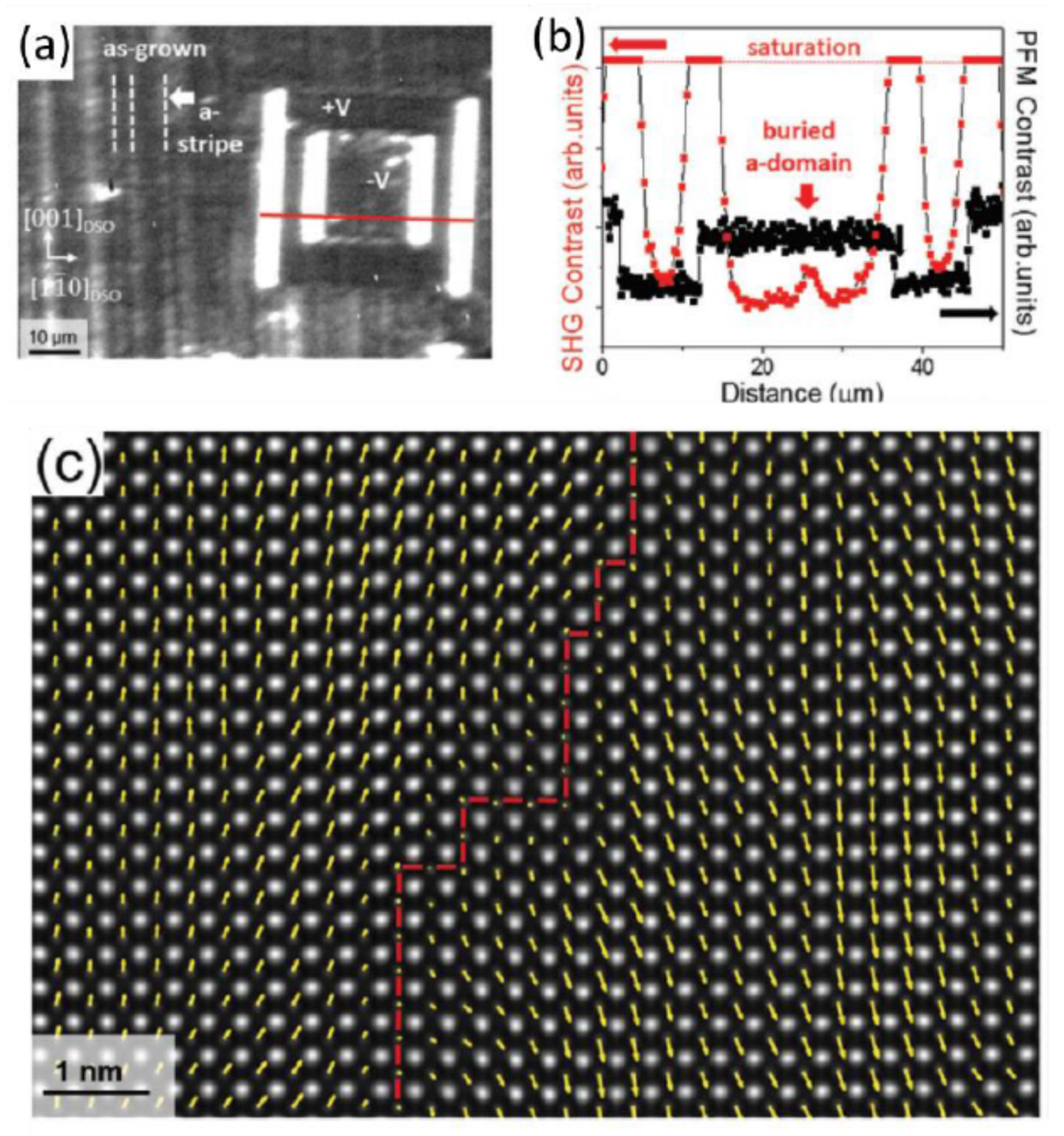
The SHG image of a ferroelectric PZT thin film exhibiting a mixed a-/c-domain state is shown in Figure 15a. The image, acquired with an in-plane polarization sensitivity [97], displays stripes along the [001]DSO orientation corresponding to [1–10]DSO-polarized a-domains together with an artificially poled region.
Strikingly, a non-zero SHG intensity is observed at the edges of the tip-poled region which cannot be explained by the assumed Ising-like 180° domain walls architecture in strained thin films [97,120]. At 180° Ising-like domain walls, the contributions of SHG response from the neighboring opposite domains interfere destructively due to a 180° phase difference [79,88]. In addition, in the present optical configuration, i.e., normal incidence, the sensitivity is not set to an out-of-plane oriented polarization. The likely explanation for a non-zero SHG signal at the domain wall is therefore the existence of an in-plane polarization component within the ferroelectric domain wall itself. This corresponds to the presence of a Néel or Bloch component of the polarization, usually observed at domain walls in ferromagnetic systems [121]. It is also interesting to note that, although the PFM line profile in the switched region in Figure 15b shows a single c-domain state, the SHG signal profile, which probes the total film thickness, reveals the presence of persisting buried a-domains in the same region [97].
The combination of STEM and SHG allows the investigation of 180° domain walls in cross-section and top view, respectively. The Ising component observed when mapping atomic displacement across the wall (Figure 15c) combined with a polarization component perpendicular to the domain wall plane identified by SHG imaging (Figure 15a), led to the demonstration of mixed Ising-Néel behavior of the PZT thin film ferroelectric wall [97,122].

4. Future Perspectives

4.1. Remaining Challenges in 3D Resolution in Thin Films

In standard ferroelectrics, 180° domain walls used to be considered Ising-like due to the strong correlation between strain and polar distortion [123]. The observation of tilted mixed Ising-Néel walls in thin films is suggesting new opportunities at these functional interfaces—one can push the analogy further, to magnetic domain walls, and expect to probe a Bloch behavior at a ferroelectric thin film domain wall. In LiTaO3 crystals [122], the detection of a polarization component within the plane of the wall by SHG allowed the identification of the Bloch-like nature of 180° domain walls, as shown in Figure 16a. The observation of such a wall type in thin films is still unreported.
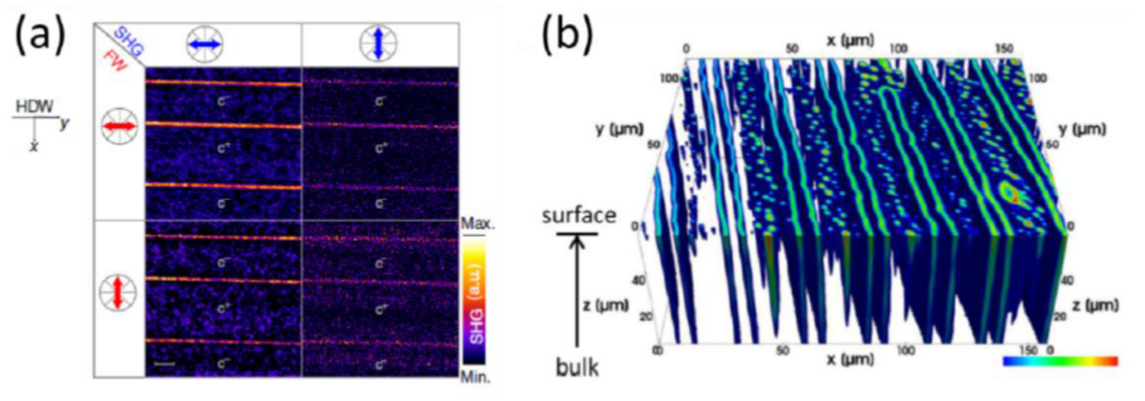
In bulk materials, imaging techniques are gaining increasing interest with the push towards the internal structure analysis of single domain walls. The full mapping of ferroelectric domain walls can now be performed during their creation at the ferroelectric phase transition and in three dimensions using temperature dependent confocal SHG microscopy [124,125,126], as shown in Figure 16b in the case of ferroelectric triglycine sulfate (TGS) [127].
Regarding thin films, the optical investigation of domain walls remains challenging due to the optical resolution limit and the limited SHG active domain wall volume. Recent progress dealing with laser-scanning SHG microscopy [128] and near-field SHG nano-imaging [129,130] where tip-enhanced SHG signals are collected with a spatial resolution approaching the submicron range [131,132] has been achieved and opens new avenues towards the symmetry analysis of nanoscale objects.

4.2. Probing Ferroelectric Heterostructures during the Growth Process

Significant advances have been made in the growth quality of thin film oxide ferroelectrics. Still, the process has been lacking control of the polar state in multilayer architectures. Most of the technological applications for ferroic thin films require a deterministic control of the domain state. Ferroelectric tunnel junctions require the stabilization of a single-domain state to maximize the polarization-orientation dependent change in conduction between the switched states [133,134]. In the case of tetragonal ferroelectric-based memory, the presence of the as-grown in-plane domains hinders the switching process of the out-of-plane polarization state [2,96]. Eliminating the in-plane domains in these systems would thus be of interest [135]. On the other hand, in multiferroic heterostructures aiming towards the electrical control of magnetization, a specific domain configuration triggers deterministic switching events [111].
To achieve full polarization control of a heterostructure, one needs to be able to monitor the polarization during the growth process. Most of the classical ferroelectric epitaxial strained systems are in fact grown in their polar phase [33,61,136]. However, none of the traditional thin-film characterization techniques can be implemented in situ due to their invasive nature and the extreme conditions during deposition, such as high substrate temperatures and pressure variations.
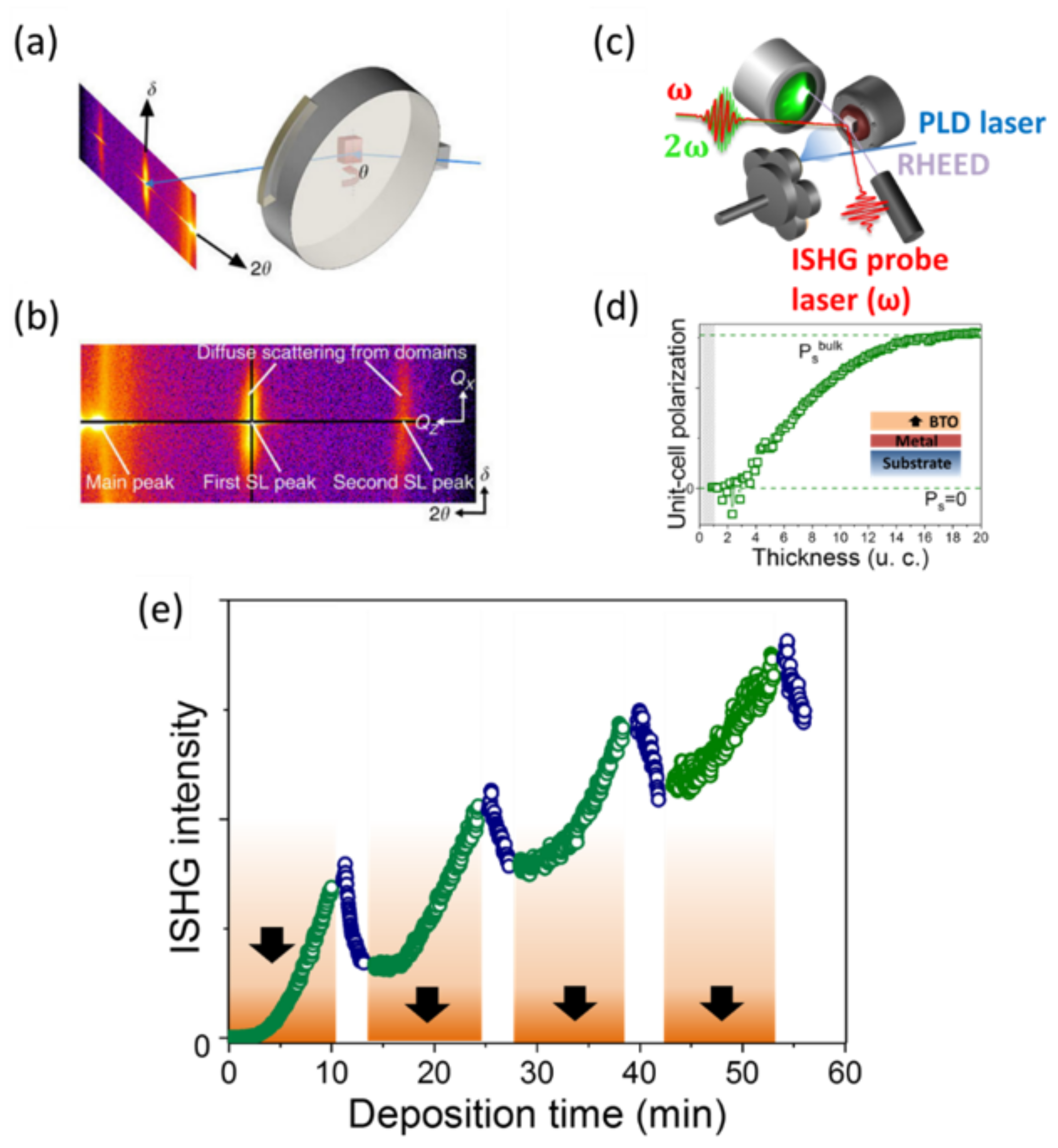
Synchrotron x-ray-based techniques, which are sensitive to periodicity in polar systems, i.e., lattice parameter and periodic domain splitting, have been used to show that past a critical thickness, BTO thin films experience an increased tetragonality during the growth process [21,136]. A schematic of the experimental setup is shown in Figure 17a,b with the corresponding measurements. These pioneering experiments revealed the emergence of the polar state during the growth and broadened the investigation of ferroelectric materials in situ. This technique, however, requires high intensity flux and is limited to highly periodic patterns.
SHG is sensitive to symmetry breaking at the emergence of all ferroic orders, which makes it an ideal technique for studying not only single- and complex-domain states but also the transition from one to another. Its non-invasive and non-destructive nature renders the optical coupling into a growth chamber conceivable [61,137,138,139]. Aside from a few attempts to characterize growth of metallic ferromagnets [138,140] and its use as a surface reaction probe [141], the SHG potential as oxide growth diagnostic tool during the pulsed laser deposition process has only recently been demonstrated [61]. A schematic of the in situ SHG (ISHG) experimental setup is shown in Figure 17c.
Direct access to the thin film polarization during its growth is achieved in real time using ISHG. The emergence of the ferroelectric polarization in BTO is shown in Figure 17d. The ability to probe multilayer systems [61,120] opens new avenues towards understanding the complex interplay between strain, interfaces, and electrostatics in oxide superlattices. Interfering signals originating from each polar constituent of a superlattice result in destructive or constructive interference depending on their relative polarization orientation. For instance, Figure 17e shows a succession of increasing ISHG intensity during the growth of ferroelectric BFO layers with parallel polarization orientation. The growth of oppositely polarized layers results in a decrease of the signal [61].
Depolarizing field, strain, interfaces, and thickness-related effects on the ferroic state of oxide thin films can now be accessed in real time during the synthesis being the key to full deposition and functionality control for interface-based oxide-electronic devices.

4.3. Towards Magnetoelectric Switching Dynamics

Now that non-destructive access to a buried ferroelectric domain configuration is gained using SHG, tracking its dynamic response to external perturbations is enabled. It is possible, for example, to apply an electric field to magnetoelectric devices and track the resulting shifts in the magnetic domain pattern. To the best of our knowledge, only a few experiments were carried out with the scope of monitoring the multiferroic, respectively magnetoelectric switching dynamics [13,142,143]. In the case of BFO thin films, the kinetics of the electric field induced reversal of the canting of the antiferromagnetically aligned spins has been investigated using time dependent dual-frequency PFM studies and first principle calculations [13]. A two-step switching process of the coupled polarization and the antiferromagnetic order results in the observed electric field induced magnetization reversal.
In another study, SHG measurements performed on bulk MnWO4 revealed a surprisingly slow reversal of the magnetic order parameter by an electric field on the time scale of milliseconds [143]. Hence, although understanding the switching dynamics rather than solely the presence of a magnetoelectric coupling is essential for any type of device application, research in this direction remains an underdeveloped topic. The non-invasive nature of SHG may now pave the way to such investigations [88,113] in multifunctional thin film architectures.
Parallel to this, alternatives to multiferroic and magnetoelectric switching mechanisms are gaining increasing interest in the push for low-energy-consuming electric-field control of magnetization. Spin-orbit-torque-based magnetic domain switching may serve as an example here [144]. Recent experiments have demonstrated a current induced magnetic switching in the picosecond regime [145].

5. Conclusions

Optical SHG is an established tool to investigate the ferroic nature of single crystals. It enabled major achievements in the field of ferroelectrics and multiferroics [16,17,18]. It relies on the ability to selectively probe several order parameters in one experiment which has a great impact on multiferroic dynamics [38] and on the observation of coupled magnetic and electric domains in a multiferroic compound [146]. Recent advances in ferroic domain engineering in thin films using epitaxial strain as a new degree of freedom are progressively rendering optical characterization of nanoscale ordered ferroic domains in thin films possible. Polar axis orientation, Curie temperature, strain tuning of the ferroelectric polarization and electric field induced switching events can now be probed non-invasively with monolayer accuracy.
Because the SHG probe has a long working distance, the investigation of the emergence of the polarization during the thin film deposition process can be designed [61]. In parallel with in situ structural knowledge gained with RHEED, in situ SHG gives the functional information in real time during the synthesis. The ISHG characterization is not affected by the extreme conditions during the growth process and can improve the understanding of ferroelectricity from the first unit cell deposited. The direct access to the ferroic domain state during growth is opening new routes towards the full control over ferroelectricity. The manipulation of the polarization orientation during the growth in a multilayer will have an important role in future applications. In addition, artificial domain walls with arbitrary polarization sequences [120] offer a wide range of physical properties [11,114,120] and can for instance be designed on demand. A possible application would deal with the ability to electrically tune the symmetry environment of a layer sandwiched between two ferroelectric films [120]. The capacity to set and verify buried polar states during the growth [61] allows tuning of the strain, charge and symmetry environment of an adjacent active layer such as symmetry sensitive topological states, metal insulator transitions or colossal magnetoresistance systems. Furthermore, in situ SHG will support efforts in the understanding of polar states in the ultrathin regime and in complex oxide-based heterostructures and superlattices. For example, the development of the technologically promising voltage amplification based on transient negative capacitance in ferroelectric heterostructures will greatly benefit from the investigation of the early stage of ferroelectric vortex formation [50,51].

Acknowledgments

The authors thank J. Schaab for fruitful discussions. The authors acknowledge funding through the SNSF R’Equip Program (Grant. No. 206021-144988).

Conflicts of Interest

The authors declare no conflict of interest.

References

  1. Scott, J.F.; De Araujo, C.A.P. Ferroelectric memories. Science 1989, 246, 1400–1405. [Google Scholar] [CrossRef] [PubMed]
  2. Setter, N.; Damjanovic, D.; Eng, L.; Fox, G.; Gevorgian, S.; Hong, S.; Kingon, A.; Kohlstedt, H.; Park, N.Y.; Stephenson, G.B.; et al. Ferroelectric thin films: Review of materials, properties, and applications. J. Appl. Phys. 2006, 100, 051606. [Google Scholar] [CrossRef]
  3. Garcia, V.; Bibes, M.; Bocher, L.; Valencia, S.; Kronast, F.; Crassous, A.; Moya, X.; Enouz-Vedrenne, S.; Gloter, A.; Imhoff, D.; et al. Ferroelectric Control of Spin Polarization. Science 2010, 327, 1106–1110. [Google Scholar] [CrossRef] [PubMed]
  4. Chanthbouala, A.; Garcia, V.; Cherifi, R.O.; Bouzehouane, K.; Fusil, S.; Moya, X.; Xavier, S.; Yamada, H.; Deranlot, C.; Mathur, N.D.; et al. A ferroelectric memristor. Nat. Mater. 2012, 11, 860–864. [Google Scholar] [CrossRef]
  5. Junquera, J.; Ghosez, P. Critical thickness for ferroelectricity in perovskite ultrathin films. Nature 2003, 422, 506–509. [Google Scholar] [CrossRef] [PubMed]
  6. Fong, D.D.; Stephenson, G.B.; Streiffer, S.K.; Eastman, J.A.; Auciello, O.; Fuoss, P.H.; Thompson, C. Ferroelectricity in ultrathin perovskite films. Science 2004, 304, 1650–1653. [Google Scholar] [CrossRef] [PubMed]
  7. Schlom, D.G.; Chen, L.Q.; Eom, C.B.; Rabe, K.M.; Streiffer, S.K.; Triscone, J.M. Strain tuning of ferroelectric thin films. Annu. Rev. Mater. Res. 2007, 37, 589–626. [Google Scholar] [CrossRef]
  8. Damodaran, A.R.; Agar, J.C.; Pandya, S.; Chen, Z.; Dedon, L.; Xu, R.; Apgar, B.; Saremi, S.; Martin, L.W. New modalities of strain-control of ferroelectric thin films. J. Phys. Condens. Matter 2016, 28, 263001. [Google Scholar] [CrossRef] [PubMed]
  9. Scott, J.F. Multiferroic memories. Nat. Mater. 2007, 6, 256–257. [Google Scholar] [CrossRef] [PubMed]
  10. Gajek, M.; Bibes, M.; Fusil, S.; Bouzehouane, K.; Fontcuberta, J.; Barthélémy, A.; Fert, A. Tunnel junctions with multiferroic barriers. Nat. Mater. 2007, 6, 296–302. [Google Scholar] [CrossRef] [PubMed]
  11. Trassin, M. Low energy consumption spintronics using multiferroic heterostructures. J. Phys. Condens. Matter 2016, 28, 033001. [Google Scholar] [CrossRef] [PubMed]
  12. Heron, J.T.; Trassin, M.; Ashraf, K.; Gajek, M.; He, Q.; Yang, S.Y.; Nikonov, D.E.; Chu, Y.H.; Salahuddin, S.; Ramesh, R. Electric-Field-Induced Magnetization Reversal in a Ferromagnet-Multiferroic Heterostructure. Phys. Rev. Lett. 2011, 107, 217202. [Google Scholar] [CrossRef] [PubMed]
  13. Heron, J.T.; Bosse, J.L.; He, Q.; Gao, Y.; Trassin, M.; Ye, L.; Clarkson, J.D.; Wang, C.; Liu, J.; Salahuddin, S.; et al. Deterministic switching of ferromagnetism at room temperature using an electric field. Nature 2014, 516, 370–373. [Google Scholar] [CrossRef] [PubMed]
  14. Heron, J.T.; Schlom, D.G.; Ramesh, R. Electric field control of magnetism using BiFeO3-based heterostructures. Appl. Phys. Rev. 2014, 1, 021303. [Google Scholar] [CrossRef]
  15. Bibes, M.; Barthélémy, A. Multiferroics: Towards a magnetoelectric memory. Nat. Mater. 2008, 7, 425–426. [Google Scholar] [CrossRef] [PubMed]
  16. Denev, S.A.; Lummen, T.T.A.; Barnes, E.; Kumar, A.; Gopalan, V. Probing Ferroelectrics Using Optical Second Harmonic Generation. J. Am. Ceram. Soc. 2011, 94, 2699–2727. [Google Scholar] [CrossRef]
  17. Fiebig, M.; Pavlov, V.V.; Pisarev, R.V. Second-harmonic generation as a tool for studying electronic and magnetic structures of crystals: Review. J. Opt. Soc. Am. B 2005, 22, 96–118. [Google Scholar] [CrossRef]
  18. Yokota, H.; Kaneshiro, J.; Uesu, Y. Optical Second Harmonic Generation Microscopy as a Tool of Material Diagnosis. Phys. Res. Int. 2012, 2012, 704634. [Google Scholar] [CrossRef]
  19. Khestanova, E.; Dix, N.; Fina, I.; Scigaj, M.; Rebled, J.M.; Magén, C.; Estradé, S.; Peiró, F.; Herranz, G.; Fontcuberta, J.; et al. Untangling electrostatic and strain effects on the polarization of ferroelectric superlattices. Adv. Funct. Mater. 2016, 26, 6446–6453. [Google Scholar] [CrossRef]
  20. Liu, G.; Chen, J.; Lichtensteiger, C.; Triscone, J.M.; Aguado-Puente, P.; Junquera, J.; Valanoor, N. Positive Effect of an Internal Depolarization Field in Ultrathin Epitaxial Ferroelectric Films. Adv. Electron. Mater. 2016, 2, 1500288. [Google Scholar] [CrossRef]
  21. Bein, B.; Hsing, H.C.; Callori, S.J.; Sinsheimer, J.; Chinta, P.V.; Headrick, R.L.; Dawber, M. In situ X-ray diffraction and the evolution of polarization during the growth of ferroelectric superlattices. Nat. Commun. 2015, 6, 10136. [Google Scholar] [CrossRef] [PubMed]
  22. Zubko, P.; Gariglio, S.; Gabay, M.; Ghosez, P.; Triscone, J.M. Interface Physics in Complex Oxide Heterostructures. Annu. Rev. Condens. Matter Phys. 2011, 2, 141–165. [Google Scholar] [CrossRef]
  23. Stephenson, G.B.; Highland, M.J. Equilibrium and stability of polarization in ultrathin ferroelectric films with ionic surface compensation. Phys. Rev. B 2011, 84, 064107. [Google Scholar] [CrossRef]
  24. Lichtensteiger, C.; Dawber, M.; Stucki, N.; Triscone, J.M.; Hoffman, J.; Yau, J.B.; Ahn, C.H.; Despont, L.; Aebi, P. Monodomain to polydomain transition in ferroelectric PbTiO3 thin films with La0.67Sr0.33MnO3 electrodes. Appl. Phys. Lett. 2007, 90, 052907. [Google Scholar] [CrossRef]
  25. Dawber, M.; Chandra, P.; Littlewood, P.B.; Scott, J.F. Depolarization corrections to the coercive field in thin-film ferroelectrics. J. Phys. Condens. Matter 2003, 15, L393–L398. [Google Scholar] [CrossRef]
  26. Streiffer, S.K.; Eastman, J.A.; Fong, D.D.; Thompson, C.; Munkholm, A.; Ramana Murty, M.V.; Auciello, O.; Bai, G.R.; Stephenson, G.B. Observation of nanoscale 180 degrees stripe domains in ferroelectric PbTiO3 thin films. Phys. Rev. Lett. 2002, 89, 067601. [Google Scholar] [CrossRef] [PubMed]
  27. Tenne, D.A.; Bruchhausen, A.; Lanzillotti-Kimura, N.D.; Fainstein, A.; Katiyar, R.S.; Cantarero, A.; Soukiassian, A.; Vaithyanathan, V.; Haeni, J.H.; Tian, W.; et al. Probing nanoscale ferroelectricity by ultraviolet Raman spectroscopy. Science 2006, 313, 1614–1616. [Google Scholar] [CrossRef] [PubMed]
  28. Dawber, M.; Stucki, N.; Lichtensteiger, C.; Gariglio, S.; Ghosez, P.; Triscone, J.M. Tailoring the properties of artificially layered ferroelectric superlattices. Adv. Mater. 2007, 19, 4153–4159. [Google Scholar] [CrossRef]
  29. Lee, H.N.; Christen, H.M.; Chisholm, M.F.; Rouleau, C.M.; Lowndes, D.H. Strong polarization enhancement in asymmetric three-component ferroelectric superlattices. Nature 2005, 433, 395–399. [Google Scholar] [CrossRef] [PubMed]
  30. Scott, J.F. Ferroelectrics go bananas. J. Phys. Condens. Matter 2008, 20, 021001. [Google Scholar] [CrossRef]
  31. Rijnders, G.J.H.M.; Koster, G.; Blank, D.H.A.; Rogalla, H. In situ monitoring during pulsed laser deposition of complex oxides using reflection high energy electron diffraction under high oxygen pressure. Appl. Phys. Lett. 1997, 70, 1888–1890. [Google Scholar] [CrossRef]
  32. Ederer, C.; Spaldin, N.A. Effect of Epitaxial Strain on the Spontaneous Polarization of Thin Film Ferroelectrics. Phys. Rev. Lett. 2005, 95, 257601. [Google Scholar] [CrossRef] [PubMed]
  33. Choi, K.J.; Biegalski, M.; Li, Y.L.; Sharan, A.; Schubert, J.; Uecker, R.; Reiche, P.; Chen, Y.B.; Pan, X.Q.; Gopalan, V.; et al. Enhancement of Ferroelectricity in Strained BaTiO3 Thin Films. Science 2004, 5, 1005–1009. [Google Scholar] [CrossRef] [PubMed]
  34. Damodaran, A.R.; Breckenfeld, E.; Chen, Z.; Lee, S.; Martin, L.W. Enhancement of ferroelectric Curie temperature in BaTiO3 films via straininduced defect dipole alignment. Adv. Mater. 2014, 26, 6341–6347. [Google Scholar] [CrossRef] [PubMed]
  35. Xu, R.; Liu, S.; Grinberg, I.; Karthik, J.; Damodaran, A.R.; Rappe, A.M.; Martin, L.W. Ferroelectric polarization reversal via successive ferroelastic transitions. Nat. Mater. 2015, 14, 79–86. [Google Scholar] [CrossRef] [PubMed]
  36. White, J.S.; Bator, M.; Hu, Y.; Luetkens, H.; Stahn, J.; Capelli, S.; Das, S.; Döbeli, M.; Lippert, T.; Malik, V.K.; et al. Strain-Induced Ferromagnetism in Antiferromagnetic LuMnO3 Thin Films. Phys. Rev. Lett. 2013, 111, 037201. [Google Scholar] [CrossRef] [PubMed]
  37. Becher, C.; Maurel, L.; Aschauer, U.; Lilienblum, M.; Magén, C.; Meier, D.; Langenberg, E.; Trassin, M.; Blasco, J.; Krug, I.P.; et al. Strain-induced coupling of electrical polarization and structural defects in SrMnO3 films. Nat. Nanotechnol. 2015, 10, 661–665. [Google Scholar] [CrossRef] [PubMed]
  38. Fiebig, M.; Lottermoser, T.; Meier, D.; Trassin, M. The evolution of multiferroics. Nat. Rev. Mater. 2016, 1, 16046. [Google Scholar] [CrossRef]
  39. Fiebig, M. Revival of the magnetoelectric effect. J. Phys. D Appl. Phys. 2005, 38, R123–R152. [Google Scholar] [CrossRef]
  40. Spaldin, N.A.; Fiebig, M. The Renaissance of Magnetoelectric Multiferroics. Science 2005, 309, 391–392. [Google Scholar] [CrossRef] [PubMed]
  41. Wang, J.; Neaton, J.B.; Zheng, H.; Nagarajan, V.; Ogale, S.B.; Liu, B.; Viehland, D.; Vaithyanathan, V.; Schlom, D.G.; Waghmare, U.V.; et al. Epitaxial BiFeO3 Multiferroic Thin Film Heterostructures. Science 2003, 299, 1719–1722. [Google Scholar] [CrossRef] [PubMed]
  42. Martí, X.; Sánchez, F.; Hrabovsky, D.; Fàbrega, L.; Ruyter, A.; Fontcuberta, J.; Laukhin, V.; Skumryev, V.; García-Cuenca, M.V.; Ferrater, C.; et al. Exchange biasing and electric polarization with YMnO3. Appl. Phys. Lett. 2006, 89, 032510. [Google Scholar] [CrossRef] [Green Version]
  43. Laukhin, V.; Skumryev, V.; Martí, X.; Hrabovsky, D.; Sánchez, F.; García-Cuenca, M.V.; Ferrater, C.; Varela, M.; Lüders, U.; Bobo, J.F.; et al. Electric-Field Control of Exchange Bias in Multiferroic Epitaxial Heterostructures. Phys. Rev. Lett. 2006, 97, 227201. [Google Scholar] [CrossRef] [PubMed] [Green Version]
  44. Ramesh, R.; Spaldin, N.A. Multiferroics: Progress and prospects in thin films. Nat. Mater. 2007, 6, 21–29. [Google Scholar] [CrossRef] [PubMed]
  45. Shimamoto, K.; Mukherjee, S.; Manz, S.; White, J.S.; Trassin, M.; Kenzelmann, M.; Chapon, L.; Lippert, T.; Fiebig, M.; Schneider, C.W.; et al. Tuning the multiferroic mechanisms of TbMnO3 by epitaxial strain. Sci. Rep. 2017, 7, 44753. [Google Scholar] [CrossRef] [PubMed]
  46. Trassin, M.; Viart, N.; Versini, G.; Loison, J.L.; Vola, J.P.; Schmerber, G.; Crégut, O.; Barre, S.; Pourroy, G.; Lee, J.H.; et al. Epitaxial thin films of multiferroic GaFeO3 on conducting indium tin oxide (001) buffered yttrium-stabilized zirconia (001) by pulsed laser deposition. Appl. Phys. Lett. 2007, 91, 202504. [Google Scholar] [CrossRef]
  47. Chu, Y.H.; Martin, L.W.; Holcomb, M.B.; Gajek, M.; Han, S.J.; He, Q.; Balke, N.; Yang, C.H.; Lee, D.; Hu, W.; et al. Electric-field control of local ferromagnetism using a magnetoelectric multiferroic. Nat. Mater. 2008, 7, 478–482. [Google Scholar] [CrossRef] [PubMed]
  48. Yadav, A.K.; Nelson, C.T.; Hsu, S.L.; Hong, Z.; Clarkson, J.D.; Schlepüetz, C.M.; Damodaran, A.R.; Shafer, P.; Arenholz, E.; Dedon, L.R.; et al. Observation of polar vortices in oxide superlattices. Nature 2016, 530, 198–201. [Google Scholar] [CrossRef] [PubMed]
  49. Shafer, P.; García-Fernández, P.; Aguado-Puente, P.; Damodaran, A.R.; Yadav, A.K.; Nelson, C.T.; Hsu, S.L.; Wojdel, J.C.; Íñiguez, J.; Martin, L.W.; et al. Emergent chirality in the electric polarization texture of titanate superlattices. Proc. Natl. Acad. Sci. USA 2018, 115, 915–920. [Google Scholar] [CrossRef] [PubMed]
  50. Khan, A.I.; Chatterjee, K.; Wang, B.; Drapcho, S.; You, L.; Serrao, C.; Bakaul, S.R.; Ramesh, R.; Salahuddin, S. Negative capacitance in a ferroelectric capacitor. Nat. Mater. 2015, 14, 182–186. [Google Scholar] [CrossRef] [PubMed]
  51. Zubko, P.; Wojdeł, J.C.; Hadjimichael, M.; Fernandez-Pena, S.; Sené, A.; Luk'yanchuk, I.; Triscone, J.M.; Íñiguez, J. Negative capacitance in multi-domain ferroelectric superlattices. Nature 2016, 534, 524–528. [Google Scholar] [CrossRef] [PubMed]
  52. Chu, Y.H.; Cruz, M.P.; Yang, C.H.; Martin, L.W.; Yang, P.L.; Zhang, J.X.; Lee, K.; Yu, P.; Chen, L.Q.; Ramesh, R. Domain Control in Multiferroic BiFeO3 through Substrate Vicinality. Adv. Mater. 2007, 19, 2662–2666. [Google Scholar] [CrossRef]
  53. Chu, Y.H.; He, Q.; Yang, C.H.; Yu, P.; Martin, L.W.; Shafer, P.; Ramesh, R. Nanoscale control of domain architectures in BiFeO3 thin films. Nano Lett. 2009, 9, 1726–1730. [Google Scholar] [CrossRef] [PubMed]
  54. Chen, Z.H.; Damodaran, A.R.; Xu, R.; Lee, S.; Martin, L.W. Effect of “symmetry mismatch” on the domain structure of rhombohedral BiFeO3 thin films. Appl. Phys. Lett. 2014, 104, 182908. [Google Scholar] [CrossRef]
  55. Haeni, J.H.; Irvin, P.; Chang, W.; Uecker, R.; Reiche, P.; Li, Y.L.; Choudhury, S.; Tian, W.; Hawley, M.E.; Craigo, B.; et al. Room-temperature ferroelectricity in strained SrTiO3. Nature 2004, 430, 758–761. [Google Scholar] [CrossRef] [PubMed]
  56. Vasudevarao, A.; Kumar, A.; Tian, L.; Haeni, J.H.; Li, Y.L.; Eklund, C.J.; Jia, Q.X.; Uecker, R.; Reiche, P.; Rabe, K.M.; et al. Multiferroic Domain Dynamics in Strained Strontium Titanate. Phys. Rev. Lett. 2006, 97, 257602. [Google Scholar] [CrossRef] [PubMed]
  57. Fennie, C.J.; Rabe, K.M. Magnetic and Electric Phase Control in Epitaxial EuTiO3 from First Principles. Phys. Rev. Lett. 2006, 97, 267602. [Google Scholar] [CrossRef] [PubMed]
  58. Lee, J.H.; Fang, L.; Vlahos, E.; Ke, X.; Jung, Y.W.; Kourkoutis, L.F.; Kim, J.W.; Ryan, P.J.; Heeg, T.; Roeckerath, M.; et al. A strong ferroelectric ferromagnet created by means of spin-lattice coupling. Nature 2010, 466, 954–958. [Google Scholar] [CrossRef] [PubMed]
  59. Highland, M.J.; Fister, T.T.; Fong, D.D.; Fuoss, P.H.; Thompson, C.; Eastman, J.A.; Streiffer, S.K.; Stephenson, G.B. Equilibrium Polarization of Ultrathin PbTiO3 with Surface Compensation Controlled by Oxygen Partial Pressure. Phys. Rev. Lett. 2011, 107, 187602. [Google Scholar] [CrossRef] [PubMed]
  60. Yu, P.; Luo, W.; Yi, D.; Zhang, J.X.; Rossell, M.D.; Yang, C.H.; You, L.; Singh-Bhalla, G.; Yang, S.Y.; He, Q.; et al. Interface control of bulk ferroelectric polarization. Proc. Natl. Acad. Sci. USA 2012, 109, 9710–9715. [Google Scholar] [CrossRef] [PubMed]
  61. De Luca, G.; Strkalj, N.; Manz, S.; Bouillet, C.; Fiebig, M.; Trassin, M. Nanoscale design of polarization in ultrathin ferroelectric heterostructures. Nat. Commun. 2017, 8, 1419. [Google Scholar] [CrossRef] [PubMed]
  62. Chen, D.; Chen, Z.; He, Q.; Clarkson, J.D.; Serrao, C.R.; Yadav, A.K.; Nowakowski, M.E.; Fan, Z.; You, L.; Gao, X.; et al. Interface Engineering of Domain Structures in BiFeO3 Thin Films. Nano Lett. 2017, 17, 486–493. [Google Scholar] [CrossRef] [PubMed]
  63. Lichtensteiger, C.; Weymann, C.; Fernandez-Pena, S.; Paruch, P.; Triscone, J.M. Built-in voltage in thin ferroelectric PbTiO3 films: The effect of electrostatic boundary conditions. New J. Phys. 2016, 18, 043030. [Google Scholar] [CrossRef]
  64. Lichtensteiger, C.; Fernandez-Pena, S.; Weymann, C.; Zubko, P.; Triscone, J.M. Tuning of the Depolarization Field and Nanodomain Structure in Ferroelectric Thin Films. Nano Lett. 2014, 14, 4205–4211. [Google Scholar] [CrossRef] [PubMed]
  65. Tang, Y.L.; Zhu, Y.L.; Ma, X.L.; Borisevich, A.Y.; Morozovska, A.N.; Eliseev, E.A.; Wang, W.Y.; Wang, Y.J.; Xu, Y.B.; Zhang, Z.D.; et al. Observation of a periodic array of flux-closure quadrants in strained ferroelectric PbTiO3 films. Science 2015, 348, 547–551. [Google Scholar] [CrossRef] [PubMed]
  66. Gruverman, A.; Wu, D.; Scott, J.F. Piezoresponse Force Microscopy Studies of Switching Behavior of Ferroelectric Capacitors on a 100-ns. Phys. Rev. Lett. 2008, 100, 097601. [Google Scholar] [CrossRef] [PubMed]
  67. Jo, J.Y.; Yang, S.M.; Kim, T.H.; Lee, H.N.; Yoon, J.-G.; Park, S.; Jo, Y.; Jung, M.H.; Noh, T.W. Nonlinear Dynamics of Domain-Wall Propagation in Epitaxial Ferroelectric Thin Films. Phys. Rev. Lett. 2009, 102, 045701. [Google Scholar] [CrossRef] [PubMed]
  68. Lefevre, C.; Demchenko, A.; Bouillet, C.; Luysberg, M.; Devaux, X.; Roulland, F.; Versini, G.; Barre, S.; Wakabayashi, Y.; Boudet, N.; et al. Nondestructive Method for the Determination of the Electric Polarization Orientation in Thin Films: Illustration on Gallium Ferrite Thin Films. Small Methods 2017, 1, 1700234. [Google Scholar] [CrossRef]
  69. Lahtinen, T.H.E.; Tuomi, J.E.; van Dijken, S. Pattern Transfer and Electric-Field-Induced Magnetic Domain Formation in Multiferroic Heterostructures. Adv. Mater. 2011, 23, 3187–3191. [Google Scholar] [CrossRef] [PubMed]
  70. Franke, K.J.A.; López González, D.; Hämäläinen, S.J.; van Dijken, S. Size Dependence of Domain Pattern Transfer in Multiferroic Heterostructures. Phys. Rev. Lett. 2014, 112, 017201. [Google Scholar] [CrossRef] [PubMed]
  71. Franke, K.J.A.; Van de Wiele, B.; Shirahata, Y.; Hämäläinen, S.J.; Taniyama, T.; van Dijken, S. Reversible Electric-Field-Driven Magnetic Domain-Wall Motion. Phys. Rev. X 2015, 5, 011010. [Google Scholar] [CrossRef]
  72. Trassin, M.; Clarkson, J.D.; Bowden, S.R.; Liu, J.; Heron, J.T.; Paull, R.J.; Arenholz, E.; Pierce, D.T.; Unguris, J. Interfacial coupling in multiferroic/ferromagnet heterostructures. Phys. Rev. B 2013, 87, 134426. [Google Scholar] [CrossRef]
  73. Unguris, J.; Bowden, S.R.; Pierce, D.T.; Trassin, M.; Ramesh, R.; Cheong, S.W.; Fackler, S.; Takeuchi, I. Simultaneous imaging of the ferromagnetic and ferroelectric structure in multiferroic heterostructures. APL Mater. 2014, 2, 076109. [Google Scholar] [CrossRef]
  74. You, L.; Wang, B.; Zou, X.; Lim, Z.S.; Zhou, Y.; Ding, H.; Chen, L.; Wang, J. Origin of the uniaxial magnetic anisotropy in La0.7Sr0.3MnO3 on stripe-domain BiFeO3. Phys. Rev. B 2013, 88, 184426. [Google Scholar] [CrossRef]
  75. Maze, J.R.; Stanwix, P.L.; Hodges, J.S.; Hong, S.; Taylor, J.M.; Cappellaro, P.; Jiang, L.; Dutt, M.V.G.; Togan, E.; Zibrov, A.S.; et al. Nanoscale magnetic sensing with an individual electronic spin in diamond. Nature 2008, 455, 644–647. [Google Scholar] [CrossRef] [PubMed]
  76. Balasubramanian, G.; Chan, I.Y.; Kolesov, R.; Al-Hmoud, M.; Tisler, J.; Shin, C.; Kim, C.; Wojcik, A.; Hemmer, P.R.; Krueger, A.; et al. Nanoscale imaging magnetometry with diamond spins under ambient conditions. Nature 2008, 455, 648–651. [Google Scholar] [CrossRef] [PubMed]
  77. Rondin, L.; Tetienne, J.P.; Hingant, T.; Roch, J.F.; Maletinsky, P.; Jacques, V. Magnetometry with nitrogen-vacancy defects in diamond. Rep. Prog. Phys. 2014, 77, 056503. [Google Scholar] [CrossRef] [PubMed]
  78. Gross, I.; Akhtar, W.; Garcia, V.; Martínez, L.J.; Chouaieb, S.; Garcia, K.; Carrétéro, C.; Barthélémy, A.; Appel, P.; Maletinsky, P.; et al. Real-space imaging of non-collinear antiferromagnetic order with a single-spin magnetometer. Nature 2017, 549, 252–256. [Google Scholar] [CrossRef] [PubMed]
  79. Kaneshiro, J.; Uesu, Y.; Fukui, T. Visibility of inverted domain structures using the second harmonic generation microscope: Comparison of interference and non-interference cases. J. Opt. Soc. Am. B 2010, 27, 888–894. [Google Scholar] [CrossRef]
  80. Lüpke, G. Characterization of semiconductor interfaces by second-harmonic generation. Surf. Sci. Rep. 1999, 35, 75–161. [Google Scholar] [CrossRef]
  81. Fröhlich, D.; Kiefer, T.; Leute, S.; Lottermoser, T. Nonlinear spectroscopy of antiferromagnetics. Appl. Phys. B 1999, 68, 465–471. [Google Scholar] [CrossRef]
  82. Rubano, A.; Fiebig, M.; Paparo, D.; Marino, A.; Maccariello, D.; di Uccio, U.S.; Granozio, F.M.; Marrucci, L.; Richter, C.; Paetel, S.; et al. Spectral and spatial distribution of polarization at the LaAlO3/SrTiO3 interface. Phys. Rev. B 2011, 83, 155405. [Google Scholar] [CrossRef]
  83. Lummen, T.T.A.; Gu, Y.; Wang, J.; Lei, S.; Xue, F.; Kumar, A.; Barnes, A.T.; Barnes, E.; Denev, S.; Belianinov, A.; et al. Thermotropic phase boundaries in classic ferroelectrics. Nat. Commun. 2014, 5, 3172. [Google Scholar] [CrossRef] [PubMed] [Green Version]
  84. Fiebig, M.; Fröhlich, D.; Sluyterman v. L., G.; Pisarev, R.V. Domain topography of antiferromagnetic Cr2O3 by second-harmonic generation. Appl. Phys. Lett. 1995, 66, 2906–2908. [Google Scholar] [CrossRef]
  85. Schoenherr, P.; Giraldo, L.M.; Lilienblum, M.; Trassin, M.; Meier, D.; Fiebig, M. Magnetoelectric Force Microscopy on Antiferromagnetic 180° Domains in Cr2O3. Materials 2017, 10, 1051. [Google Scholar] [CrossRef] [PubMed]
  86. Matsubara, M.; Manz, S.; Mochizuki, M.; Kubacka, T.; Iyama, A.; Aliouane, N.; Kimura, T.; Johnson, S.L.; Meier, D.; Fiebig, M. Magnetoelectric domain control in multiferroic TbMnO3. Science 2015, 348, 1112–1115. [Google Scholar] [CrossRef] [PubMed]
  87. Manz, S.; Matsubara, M.; Lottermoser, T.; Büchi, J.; Iyama, A.; Kimura, T.; Meier, D.; Fiebig, M. Reversible Optical Switching of Antiferromagnetism in TbMnO3. Nat. Photonics 2016, 10, 653–656. [Google Scholar] [CrossRef]
  88. Trassin, M.; De Luca, G.; Manz, S.; Fiebig, M. Probing Ferroelectric Domain Engineering in BiFeO3 Thin Films by Second Harmonic Generation. Adv. Mater. 2015, 27, 4871–4876. [Google Scholar] [CrossRef] [PubMed]
  89. Dick, B.; Gierulski, A.; Marowsky, G.; Reider, G.A. Determination of the nonlinear optical susceptibility χ(2) of surface layers by sum and difference frequency generation in reflection and transmission. Appl. Phys. B 1985, 38, 107–116. [Google Scholar] [CrossRef]
  90. Guyot-Sionnest, P.; Chen, W.; Shen, Y.R. General considerations on optical second-harmonic generation from surfaces and interfaces. Phys. Rev. B 1986, 33, 8254–8263. [Google Scholar] [CrossRef]
  91. Nagarajan, V.; Jenkins, I.G.; Alpay, S.P.; Li, H.; Aggarwal, S.; Salamanca-Riba, L.; Roytburd, A.L.; Ramesh, R. Thickness dependence of structural and electrical properties in epitaxial lead zirconate titanate films. J. Appl. Phys. 1999, 86, 595–602. [Google Scholar] [CrossRef]
  92. Nesterov, O.; Matzen, S.; Magen, C.; Vlooswijk, A.H.G.; Catalan, G.; Noheda, B. Thickness scaling of ferroelastic domains in PbTiO3 films on DyScO3. Appl. Phys. Lett. 2013, 103, 142901. [Google Scholar] [CrossRef]
  93. Feigl, L.; Yudin, P.; Stolichnov, I.; Sluka, T.; Shapovalov, K.; Mtebwa, M.; Sandu, C.S.; Wei, X.K.; Tagantsev, A.K.; Setter, N. Controlled stripes of ultrafine ferroelectric domains. Nat. Commun. 2014, 5, 4677. [Google Scholar] [CrossRef] [PubMed]
  94. Su, D.; Meng, Q.; Vaz, C.A.F.; Han, M.G.; Segal, Y.; Walker, F.J.; Sawicki, M.; Broadbridge, C.; Ahn, C.H. Origin of 90° domain wall pinning in Pb(Zr0.2Ti0.8)O3 heteroepitaxial thin films. Appl. Phys. Lett. 2011, 99, 102902. [Google Scholar] [CrossRef]
  95. Gao, P.; Britson, J.; Jokisaari, J.R.; Nelson, C.T.; Baek, S.H.; Wang, Y.; Eom, C.B.; Chen, L.Q.; Pan, X. Atomic-scale mechanisms of ferroelastic domain-wall-mediated ferroelectric switching. Nat. Commun. 2013, 4, 2791. [Google Scholar] [CrossRef]
  96. Gao, P.; Britson, J.; Nelson, C.T.; Jokisaari, J.R.; Duan, C.; Trassin, M.; Baek, S.H.; Guo, H.; Li, L.; Wang, Y.; et al. Ferroelastic domain switching dynamics under electrical and mechanical excitations. Nat. Commun. 2014, 5, 3801. [Google Scholar] [CrossRef] [PubMed]
  97. De Luca, G.; Rossell, M.D.; Schaab, J.; Viart, N.; Fiebig, M.; Trassin, M. Domain wall architecture in tetragonal ferroelectric thin films. Adv. Mater. 2017, 29, 1605145. [Google Scholar] [CrossRef] [PubMed]
  98. Zeches, R.J.; Rossell, M.D.; Zhang, J.X.; Hatt, A.J.; He, Q.; Yang, C.H.; Kumar, A.; Wang, C.H.; Melville, A.; Adamo, C.; et al. A Strain-Driven Morphotropic Phase Boundary in BiFeO3. Science 2009, 326, 977–980. [Google Scholar] [CrossRef] [PubMed]
  99. Sando, D.; Barthélémy, A.; Bibes, M. BiFeO3 epitaxial thin films and devices: Past, present and future. J. Phys. Condens. Matter 2014, 26, 47320. [Google Scholar] [CrossRef] [PubMed]
  100. Beekman, C.; Siemons, W.; Ward, T.Z.; Chi, M.; Howe, J.; Biegalski, M.D.; Balke, N.; Maksymovych, P.; Farrar, A.K.; Romero, J.B.; et al. Phase Transitions, Phase Coexistence, and Piezoelectric Switching Behavior in Highly Strained BiFeO3 Films. Adv. Mater. 2013, 25, 5561–5567. [Google Scholar] [CrossRef] [PubMed]
  101. Kumar, A.; Denev, S.; Zeches, R.J.; Vlahos, E.; Podraza, N.J.; Melville, A.; Schlom, D.G.; Ramesh, R.; Gopalan, V. Probing mixed tetragonal/rhombohedral-like monoclinic phases in strained bismuth ferrite films by optical second harmonic generation. Appl. Phys. Lett. 2010, 97, 112903. [Google Scholar] [CrossRef]
  102. Haislmaier, R.C.; Podraza, N.J.; Denev, S.; Melville, A.; Schlom, D.G.; Gopalan, V. Large nonlinear optical coefficients in pseudo-tetragonal BiFeO3 thin films. Appl. Phys. Lett. 2013, 103, 031906. [Google Scholar] [CrossRef]
  103. Kumar, A.; Rai, R.C.; Podraza, N.J.; Denev, S.; Ramirez, M.; Chu, Y.H.; Martin, L.W.; Ihlefeld, J.; Heeg, T.; Schubert, J.; et al. Linear and nonlinear optical properties of BiFeO3. Appl. Phys. Lett. 2008, 92, 121915. [Google Scholar] [CrossRef]
  104. Zhang, J.; Ke, X.; Gou, G.; Seidel, J.; Xiang, B.; Yu, P.; Liang, W.I.; Minor, A.M.; Chu, Y.H.; van Tendeloo, G.; et al. A nanoscale shape memory oxide. Nat. Commun. 2013, 4, 2768. [Google Scholar] [CrossRef] [PubMed]
  105. Seidel, J.; Trassin, M.; Zhang, Y.; Maksymovych, P.; Uhlig, T.; Milde, P.; Köhler, D.; Baddorf, A.P.; Kalinin, S.V.; Eng, L.M.; et al. Electronic Properties of Isosymmetric Phase Boundaries in Highly Strained Ca-Doped BiFeO3. Adv. Mater. 2014, 26, 4376–4380. [Google Scholar] [CrossRef] [PubMed]
  106. Roh, C.J.; Hamh, S.Y.; Woo, C.S.; Kim, K.E.; Yang, C.H.; Lee, J.S. Ferroelectric domain states of a tetragonal BiFeO3 thin film investigated by second harmonic generation microscopy. Nanoscale Res. Lett. 2017, 12, 353. [Google Scholar] [CrossRef] [PubMed]
  107. Wang, J.S.; Jin, K.J.; Guo, H.Z.; Gu, J.X.; Wan, Q.; He, X.; Li, X.L.; Xu, X.L.; Yang, G.Z. Evolution of structural distortion in BiFeO3 thin films probed by second-harmonic generation. Sci. Rep. 2016, 6, 38268. [Google Scholar] [CrossRef] [PubMed]
  108. Zhao, T.; Scholl, A.; Zavaliche, F.; Lee, K.; Barry, M.; Doran, A.; Cruz, M.P.; Chu, Y.H.; Ederer, C.; Spaldin, N.A.; et al. Electrical control of antiferromagnetic domains in multiferroic BiFeO3 films at room temperature. Nat. Mater. 2006, 5, 823–829. [Google Scholar] [CrossRef] [PubMed]
  109. Holcomb, M.B.; Martin, L.W.; Scholl, A.; He, Q.; Yu, P.; Yang, C.H.; Yang, S.Y.; Glans, P.A.; Valvidares, M.; Huijben, M.; et al. Probing the evolution of antiferromagnetism in multiferroics. Phys. Rev. B 2010, 81, 134406. [Google Scholar] [CrossRef]
  110. Zhou, Z.; Trassin, M.; Gao, Y.; Gao, Y.; Qiu, D.; Ashraf, K.; Nan, T.; Yang, X.; Bowden, S.R.; Pierce, D.T.; et al. Probing electric field control of magnetism using ferromagnetic resonance. Nat. Commun. 2015, 6, 6082. [Google Scholar] [CrossRef] [PubMed]
  111. Balke, N.; Choudhury, S.; Jesse, S.; Huijben, M.; Chu, Y.H.; Baddorf, A.P.; Chen, L.Q.; Ramesh, R.; Kalinin, S.V. Deterministic control of ferroelastic switching in multiferroic materials. Nat. Nanotechnol. 2009, 4, 868–875. [Google Scholar] [CrossRef] [PubMed]
  112. Crassous, A.; Sluka, T.; Tagantsev, A.K.; Setter, N. Polarization charge as a reconfigurable quasi-dopant in ferroelectric thin films. Nat. Nanotechnol. 2015, 10, 614–618. [Google Scholar] [CrossRef] [PubMed]
  113. Chauleau, J.Y.; Haltz, E.; Carrétéro, C.; Fusil, S.; Viret, M. Multi-stimuli manipulation of antiferromagnetic domains assessed by second-harmonic imaging. Nat. Mater. 2017, 16, 803–807. [Google Scholar] [CrossRef] [PubMed]
  114. Meier, D. Functional domain walls in multiferroics. J. Phys. Condens. Matter 2015, 27, 463003. [Google Scholar] [CrossRef] [PubMed]
  115. Seidel, J.; Martin, L.W.; He, Q.; Zhan, Q.; Chu, Y.H.; Rother, A.; Hawkridge, M.E.; Maksymovych, P.; Yu, P.; Gajek, M.; et al. Conduction at domain walls in oxide multiferroics. Nat. Mater. 2009, 8, 229–234. [Google Scholar] [CrossRef] [PubMed]
  116. Mundy, J.A.; Schaab, J.; Kumagai, Y.; Cano, A.; Stengel, M.; Krug, I.P.; Gottlob, D.M.; Doğanay, H.; Holtz, M.E.; Held, R.; et al. Functional electronic inversion layers at ferroelectric domain walls. Nat. Mater. 2017, 16, 622–627. [Google Scholar] [CrossRef] [PubMed]
  117. Sharma, P.; Zhang, Q.; Sando, D.; Lei, C.H.; Liu, Y.; Li, J.; Nagarajan, V.; Seidel, J. Nonvolatile ferroelectric domain wall memory. Sci. Adv. 2017, 3, e1700512. [Google Scholar] [CrossRef] [PubMed]
  118. Holtz, M.E.; Shapovalov, K.; Mundy, J.A.; Chang, C.S.; Yan, Z.; Bourret, E.; Muller, D.A.; Meier, D.; Cano, A. Topological Defects in Hexagonal Manganites: Inner Structure and Emergent Electrostatics. Nano Lett. 2017, 17, 5883–5890. [Google Scholar] [CrossRef] [PubMed]
  119. Tolédano, P.; Guennou, M.; Kreisel, J. Order-parameter symmetries of domain walls in ferroelectrics and ferroelastics. Phys. Rev. B 2014, 89, 134104. [Google Scholar] [CrossRef]
  120. Becher, C.; Trassin, M.; Lilienblum, M.; Nelson, C.T.; Suresha, S.J.; Yi, D.; Yu, P.; Ramesh, R.; Fiebig, M.; Meier, D. Functional ferroic heterostructures with tunable integral symmetry. Nat. Commun. 2014, 5, 4295. [Google Scholar] [CrossRef] [PubMed]
  121. Dennis, C.L.; Borges, R.P.; Buda, L.D.; Ebels, U.; Gregg, J.F.; Hehn, M.; Jouguelet, E.; Ounadjela, K.; Petej, I.; Prejbeanu, I.L.; et al. The defining length scales of mesomagnetism: A Review. J. Phys. Condens. Matter 2002, 14, R1175–R1262. [Google Scholar] [CrossRef]
  122. Cherifi-Hertel, S.; Bulou, H.; Hertel, R.; Taupier, G.; Dorkenoo, K.D.; Andreas, C.; Guyonnet, J.; Gaponenko, I.; Gallo, K.; Paruch, P. Non-Ising and chiral ferroelectric domain walls revealed by nonlinear optical microscopy. Nat. Commun. 2017, 8, 15768. [Google Scholar] [CrossRef] [PubMed]
  123. Lee, D.; Behera, R.K.; Wu, P.; Xu, H.; Sinnott, S.B.; Phillpot, S.R.; Chen, L.Q.; Gopalan, V. Mixed Bloch-Néel-Ising character of 180° ferroelectric domain walls. Phys. Rev. B 2009, 80, 060102. [Google Scholar] [CrossRef]
  124. Flörsheimer, M.; Paschotta, R.; Kubitscheck, U.; Brillert, C.; Hofmann, D.; Heuer, L.; Schreiber, G.; Verbeek, C.; Sohler, W.; Fuchs, H. Second-harmonic imaging of ferroelectric domains in LiNbO3 with micron resolution in lateral and axial directions. Appl. Phys. B 1998, 67, 593–599. [Google Scholar] [CrossRef]
  125. Sheng, Y.; Best, A.; Butt, H.J.; Krolikowski, W.; Arie, A.; Koynov, K. Three-dimensional ferroelectric domain visualization by Čerenkov-type second harmonic generation. Opt. Express 2010, 18, 16539. [Google Scholar] [CrossRef] [PubMed]
  126. Kämpfe, T.; Reichenbach, P.; Schröder, M.; Haußmann, A.; Eng, L.M.; Woike, T.; Soergel, E. Optical three-dimensional profiling of charged domain walls in ferroelectrics by Cherenkov second-harmonic generation. Phys. Rev. B 2014, 89, 035314. [Google Scholar] [CrossRef]
  127. Wehmeier, L.; Kämpfe, T.; Haußmann, A.; Eng, L.M. In Situ 3D Observation of the Domain Wall Dynamics in a Triglycine Sulfate Single Crystal upon Ferroelectric Phase Transition. Phys. Status Solidi (RRL)-Rapid Res. Lett. 2017, 11, 1700267. [Google Scholar] [CrossRef]
  128. Prylepa, A.; Reitböck, C.; Cobet, M.; Jesacher, A.; Jin, X.; Adelung, R.; Schatzl-Linder, M.; Luckeneder, G.; Stellnberger, K.H.; Steck, T.; et al. Material characterisation with methods of nonlinear optics. J. Phys. D Appl. Phys. 2018, 51, 043001. [Google Scholar] [CrossRef]
  129. Neacsu, C.C.; van Aken, B.B.; Fiebig, M.; Raschke, M.B. Second-harmonic near-field imaging of ferroelectric domain structure of YMnO3. Phys. Rev. B 2009, 79, 100107. [Google Scholar] [CrossRef]
  130. Park, K.D.; Khatib, O.; Kravtsov, V.; Clark, G.; Xu, X.; Raschke, M.B. Hybrid tip-enhanced nanospectroscopy and nanoimaging of monolayer WSe2 with local strain control. Nano Lett. 2016, 16, 2621–2627. [Google Scholar] [CrossRef] [PubMed]
  131. Damodaran, A.R.; Clarkson, J.D.; Hong, Z.; Liu, H.; Yadav, A.K.; Nelson, C.T.; Hsu, S.L.; McCarter, M.R.; Park, K.D.; Kravtsov, V.; et al. Phase coexistence and electric-field control of toroidal order in oxide superlattices. Nat. Mater. 2017, 16, 1003–1009. [Google Scholar] [CrossRef] [PubMed]
  132. Atkin, J.M.; Berweger, S.; Jones, A.C.; Raschke, M.B. Nano-optical imaging and spectroscopy of order, phases, and domains in complex solids. Adv. Phys. 2012, 61, 745–842. [Google Scholar] [CrossRef]
  133. Zhuravlev, M.Y.; Sabirianov, R.F.; Jaswal, S.S.; Tsymbal, E.Y. Giant Electroresistance in Ferroelectric Tunnel Junctions. Phys. Rev. Lett. 2005, 94, 246802. [Google Scholar] [CrossRef]
  134. Sanchez-Santolino, G.; Tornos, J.; Hernandez-Martin, D.; Beltran, J.I.; Munuera, C.; Cabero, M.; Perez-Muñoz, A.; Ricote, J.; Mompean, F.; Garcia-Hernandez, M.; et al. Resonant electron tunnelling assisted by charged domain walls in multiferroic tunnel junctions. Nat. Nanotechnol. 2017, 12, 655–662. [Google Scholar] [CrossRef] [PubMed]
  135. Khan, A.I.; Marti, X.; Serrao, C.; Ramesh, R.; Salahuddin, S. Voltage-Controlled Ferroelastic Switching in Pb(Zr0.2Ti0.8)O3 Thin Films. Nano Lett. 2015, 15, 2229–2234. [Google Scholar] [CrossRef] [PubMed]
  136. Sinsheimer, J.; Callori, S.J.; Ziegler, B.; Bein, B.; Chinta, P.V.; Ashrafi, A.; Headrick, R.L.; Dawber, M. In-situ X-ray diffraction study of the growth of highly strained epitaxial BaTiO3 thin films. Appl. Phys. Lett. 2013, 103, 242904. [Google Scholar] [CrossRef]
  137. Rubano, A.; Günter, T.; Lilienblum, M.; Aruta, C.; Granozio, F.M.; di Uccio, U.S.; Marrucci, L.; Paparo, D.; Fiebig, M. Optical second harmonic imaging as a diagnostic tool for monitoring epitaxial oxide thin-film growth. Appl. Surf. Sci. 2015, 327, 413–417. [Google Scholar] [CrossRef]
  138. Jin, Q.Y.; Regensburger, H.; Vollmer, R.; Kirschner, J. Periodic Oscillations of the Surface Magnetization during the Growth of Co Films on Cu(001). Phys. Rev. Lett. 1998, 80, 4056–4059. [Google Scholar] [CrossRef]
  139. Yamada, C.; Kimura, T. In-situ surface second-harmonic generation study of epitaxial growth of GaAs. Jpn. J. Appl. Phys. 1995, 34, 1102–1105. [Google Scholar] [CrossRef]
  140. Jähnke, V.; Conrad, U.; Güdde, J.; Matthias, E. SHG investigations of the magnetization of thin Ni and Co films on Cu(001). Appl. Phys. B 1999, 68, 485–489. [Google Scholar] [CrossRef]
  141. Hu, X.F.; Xu, Z.; Lim, D.; Downer, M.C.; Parkinson, P.S.; Gong, B.; Hess, G.; Ekerdt, J.G. In situ optical second-harmonic-generation monitoring of disilane adsorption and hydrogen desorption during epitaxial growth on Si(001). Appl. Phys. Lett. 1997, 71, 1376–1378. [Google Scholar] [CrossRef]
  142. Roy, K.; Bandyopadhyay, S.; Atulasimha, J. Switching dynamics of a magnetostrictive single-domain nanomagnet subjected to stress. Phys. Rev. B 2011, 83, 224412. [Google Scholar] [CrossRef]
  143. Hoffmann, T.; Thielen, P.; Becker, P.; Bohatý, L.; Fiebig, M. Time-resolved imaging of magnetoelectric switching in multiferroic MnWO4. Phys. Rev. B 2011, 84, 184404. [Google Scholar] [CrossRef]
  144. Miron, I.M.; Gaudin, G.; Auffret, S.; Rodmacq, B.; Schuhl, A.; Pizzini, S.; Vogel, J.; Gambardella, P. Current-driven spin torque induced by the Rashba effect in a ferromagnetic metal layer. Nat. Mater. 2010, 9, 230–234. [Google Scholar] [CrossRef] [PubMed]
  145. Garello, K.; Avci, C.O.; Miron, I.M.; Baumgartner, M.; Ghosh, A.; Auffret, S.; Boulle, O.; Gaudin, G.; Gambardella, P. Ultrafast magnetization switching by spin-orbit torques. Appl. Phys. Lett. 2014, 105, 212402. [Google Scholar] [CrossRef]
  146. Fiebig, M.; Lottermoser, T.; Fröhlich, D.; Goltsev, A.V.; Pisarev, R.V. Observation of coupled magnetic and electric domains. Nature 2002, 419, 818–820. [Google Scholar] [CrossRef] [PubMed]
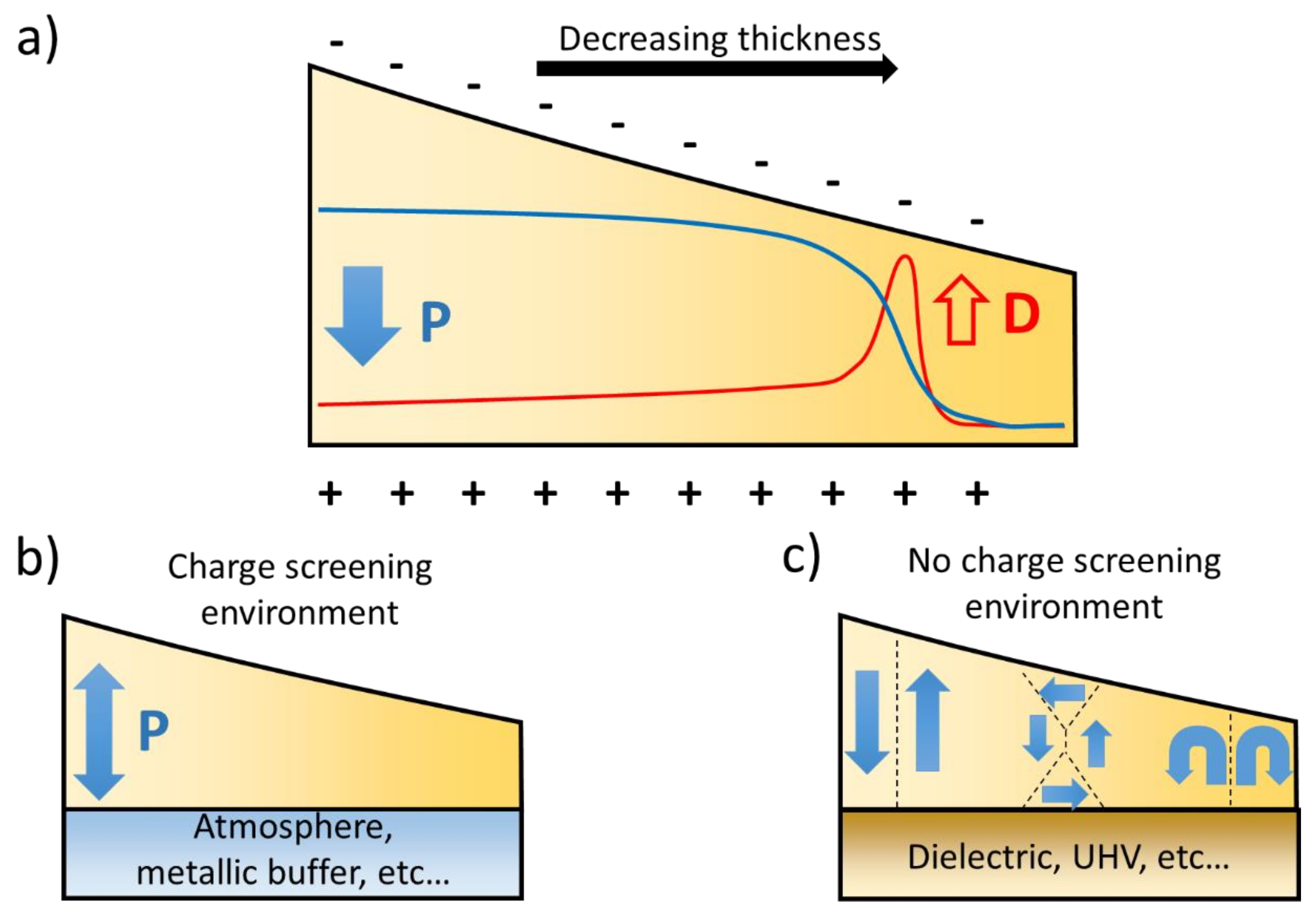
Figure 1. Thickness dependence of the polar state in ferroelectric thin films. (a) The polarization P and depolarizing field D have a thickness dependence, resulting in the minor influence of the depolarizing field on polarization in the high thickness range and a suppression of polarization at low thicknesses; (b) When the bound charges can be screened by the environment, the depolarizing field is minimized and a single domain state can be stabilized over a wide thickness range; (c) In the absence of charge screening, however, the depolarizing field favors a multi-domain state. Flux closure or vortices can also form in a specific thickness or strain regime.
Applsci 08 00570 g001
Figure 2. Domain engineering in ferroic thin films. (ac) Control of the number of ferroelectric variants in BFO using STO substrate orientation. (001), (110) and (111) orientations correspond to (ac), respectively. Reproduced with permission from [52], Copyright Wiley-VCH Verlag GmbH and Co. KGaA, 2007); (d) The insertion of a dielectric ultrathin lanthanum-doped BFO layer between BFO and the metallic SrRuO3 (SRO) buffer induces a transition from a 71° stripe domain architecture to a 109° stripe domain pattern. Reprinted with permission from [62], Copyright American Chemical Society, 2016; (e) The insertion of a dielectric STO layer between the SRO and PbTiO3 (PTO) ferroelectric film stabilizes nanoscale 180° domains. Reprinted with permission from [64], Copyright American Chemical Society, 2014.
Applsci 08 00570 g002
Figure 3. Scanning transmission electron microscopy on complex polar domains. (a) Observation of ferroelectric vortices in PTO/STO superlattice. Reprinted by permission from [48], Copyright Macmillan Publishers Ltd., 2016. (b) Close-up into a single vortex. (c) Flux-closure domain patterns in a PTO/STO multilayer system. From. Reprinted with permission from [65], Copyright AAAS, 2015.
Applsci 08 00570 g003
Figure 4. Imaging multiferroic domains in BFO thin films. (a) SEMPA showing the in-plane orientation of the ferromagnetic domains in a CoFe layer deposited on top of the multiferroic film; (b) Line scans from the backscattering electrons (red curve), SEMPA (filled black squares) and calculations (open blue squares) with a 7 mT effective coupling field highlight the coupling between the multiferroic and the ferromagnet. (a,b) Reprinted with permission from [72], Copyright the American Physical Society, 2013; (c) Magnetic field distribution recorded on a single ferroelectric domain showing the existence of a spin cycloid within a single ferroelectric domain; (d) Representation of the spin density wave (top) showing an uncompensated moment, the line scan (bottom) shows the magnetic field distribution along the cycloid propagation direction. Reprinted by permission from [78], Copyright Macmillan Publishers Ltd.: Nature, 2017.
Applsci 08 00570 g004
Figure 5. Typical SHG measurement setup in transmission. The incident probe beam is linearly polarized by a Glan-Taylor prism (GT1). The polarization of the probe beam is then set to an arbitrary polarization state by a rotatable wave-plate. WP1 can be a half-wave-plate for linear polarization states or a quarter-wave-plate to achieve circular polarization. The spot size on the sample is controlled by a focusing lens L1. Low-pass filter F1 removes any second harmonic light generated in the polarization optics before the sample. The fundamental beam and higher order harmonics are blocked by band/high-pass F2 and low-pass F3 filters. The SHG light is collected by L2, and the polarization state is analyzed by projection on a second, rotatable, GT prism (GT2). The SHG intensity is integrated after passing a monochromator (MC) and photomultiplier tube (PMT). In the case of spatially-resolved SHG, L2 is exchanged for a (microscope) objective lens and the detection unit is replaced with a CCD camera. The incident angle θ can be changed by rotating the sample around the y-axis.
Applsci 08 00570 g005
Figure 6. Imaging ferroic domains in bulk using SHG. (a) Ferroelectric domain structure in BaTiO3 (BTO). The scale bar is 8 µm. (b) Observation of orthorhombic twinning in a BTO crystal. The scale bar is 12 µm. Reprinted by permission from [83], Copyright Macmillan Publishers Ltd.: Nature Communications, 2014. (c) Antiferromagnetic domains in Cr2O3, reprinted with permission from [84] Copyright AIP Publishing, 1995. Scale bar is 1 mm. (d) Multiferroic domains in TbMnO3, Reprinted with permission from [86], Copyright AAAS, 2015.
Applsci 08 00570 g006
Figure 7. Substrate- and surface-related SHG. (a) Polarizer measurements performed on DSO in normal incidence (0° tilt angle) transmission. (b) Surface-related SHG response in anisotropy configuration at 45° incidence in reflection from an SRO thin film grown on STO substrate.
Applsci 08 00570 g007
Figure 8. Optical detection of a-domains in PZT. (a) PFM scan of a single domain, c-oriented film. The scale bar is 1 µm. (b) SHG tilt scan showing the increased contribution from c-domains with increased tilting angle. The scale bar is 2 µm. (c) Polarizer measurement at a 40° tilt angle evidencing a single polar axis in the film. (df) Corresponding PFM, tilt scan and polarizer measurement at normal incidence for a mixed a-/c-domain state, respectively.
Applsci 08 00570 g008
Figure 9. SHG on domain-engineered multiferroic BFO. (a) PFM scan of a stripe-like domain BFO film. (b) Polarizer measurement evidencing a net in-plane polarization in the film. (c,d) Corresponding PFM and polarizer measurement for an isotropic domain distribution, respectively. The signal observation in (d) does not depend on the sample crystalline orientation. Reproduced with permission from [88], Copyright Wiley-VCH Verlag GmbH and Co. KGaA, 2015.
Applsci 08 00570 g009
Figure 10. SHG to distinguish different monoclinic phases. (a,b) SHG anisotropy measurements collected at normal incidence for T- and R-phase, respectively. Reproduced with permission from [88] Copyright Wiley-VCH Verlag GmbH and Co. KGaA, 2015. (c) SHG intensity for different BFO films at different angles of incidence. (d,e) Polarizer measurements allow distinguishing the two phases. (ce) Reprinted with the permission from [101], Copyright AIP Publishing, 2010.
Applsci 08 00570 g010
Figure 11. SHG to probe strain relaxation. (ac) Polarizer measurements for different BFO film thicknesses can quantify the amount of T- and R-phases associated with a certain thickness. Reprinted from [107].
Applsci 08 00570 g011
Figure 12. Switching events in BFO thin films. (a,b) Coupled switching of ferroelectric, (a) and antiferromagnetic (b) orders in BFO thin films. The one-to-one domain correlation persists after local voltage application (within the area delimited by the yellow dashed line). Reprinted by permission from [108], Copyright Macmillan Publishers Ltd.: Nature Materials, 2006. (ce) SHG images of an SPM tip-poled 100 × 50 μm2 field in BFO on DSO (110), using surface SHG interference to selectively image domain walls (c), surface (d) or domain polarization direction (e), respectively. (f,g) Corresponding SHG polarization dependence and in-plane PFM images outside (f) and inside (g) the switched area (cg). Reproduced with permission from [88], Copyright Wiley-VCH Verlag GmbH and Co. KGaA, 2015.
Applsci 08 00570 g012
Figure 13. Multiferroic domain mapping in a BFO thin film. (a) SHG imaging set up. (b) The spatially resolved anisotropy corresponding to antiferromagnetic domains. (c) Polarizer measurements in different areas of the sample showing a spatially distributed anisotropy in the polarizer symmetry. Reprinted by permission from [113]. Copyright Macmillan Publishers Ltd.: Nature Materials, 2017.
Applsci 08 00570 g013
Figure 14. Ferroelectric domain structure in a BFO thin film on La0.7Sr0.3MnO3 buffered DSO capped with 4 nm Pt. (a) PFM image of the Pt-capped BFO shows no ferroelectric domain contrast. For comparison, the inset shows the domain structure of the uncapped BFO layer. (b) SHG polarizer measurement identifies a polar axis along the vertical orientation, corresponding to the macroscopic net polarization direction, indicated by the white arrows in the insets of (a,b). Reproduced with permission from [88], Copyright Wiley-VCH Verlag GmbH and Co. KGaA, 2015.
Applsci 08 00570 g014
Figure 15. Polar behavior of a ferroelectric domain wall. (a) SHG imaging a stripe a-domain pattern in a PZT thin film. A tip-induced switching event is visible on the right side (+V and –V indicate where a positive and negative voltage was applied by the scanning tip, respectively). (b) Piezoresponse force microscopy and SHG intensity line scans over the section indicated by the red line in (a). (c) High-angle annular dark-field (HAADF) STEM image overlaid with polarization vectors showing a smooth Néel-like rotation combined with an Ising-like polarization decrease across the domain wall. Reproduced with permission from [97], Copyright Wiley-VCH Verlag GmbH and Co. KGaA, 2016.
Applsci 08 00570 g015
Figure 16. Three-dimensional structure of domain walls in ferroelectric crystals. (a) SHG image of periodic Bloch domain walls in LiTaO3 crystals. Reprinted from [122]. (b) Three dimensional SHG microscopy image of domains walls in TGS. Reproduced with permission from [127], Copyright Wiley-VCH Verlag GmbH and Co. KGaA, 2017.
Applsci 08 00570 g016
Figure 17. Characterization of the polar state during the growth. (a) Schematic of the in situ X-ray diffraction experiment, (b) Example of diffraction results for a BTO/STO superlattice. (a,b) Reprinted from [21]. (c) Schematic of the in situ SHG experimental setup. (d) In situ SHG measurement showing the emergence of polarization during the growth of a BTO thin film. (e) In situ SHG during the deposition of a BFO/SRO multilayer with a parallel polarization configuration. (ce) Reprinted with from [61].
Applsci 08 00570 g017