Battery Management System Hardware Concepts: An Overview

 ,
,
Abstract
:1. Introduction
2. Battery Management System Requirements
- Acquisition of temperature,
- Acquisition of voltage (individual cells, stack or whole pack and Direct Current (DC)-link voltage as well),
- Acquisition of current (stack or whole pack),
- BMS master module and BMS slave modules (that acquire above mentioned values),
- Battery pack and surrounding application (e.g., car, aeroplane).
- Robustness against Electromagnetic interference (EMI).
- Contactors and
- Redundancy of the system in terms of functional safety.
- Galvanic isolation of functional systems.
- Balancing
- Power consumption, size, weight, etc.
2.1. Temperature Acquisition
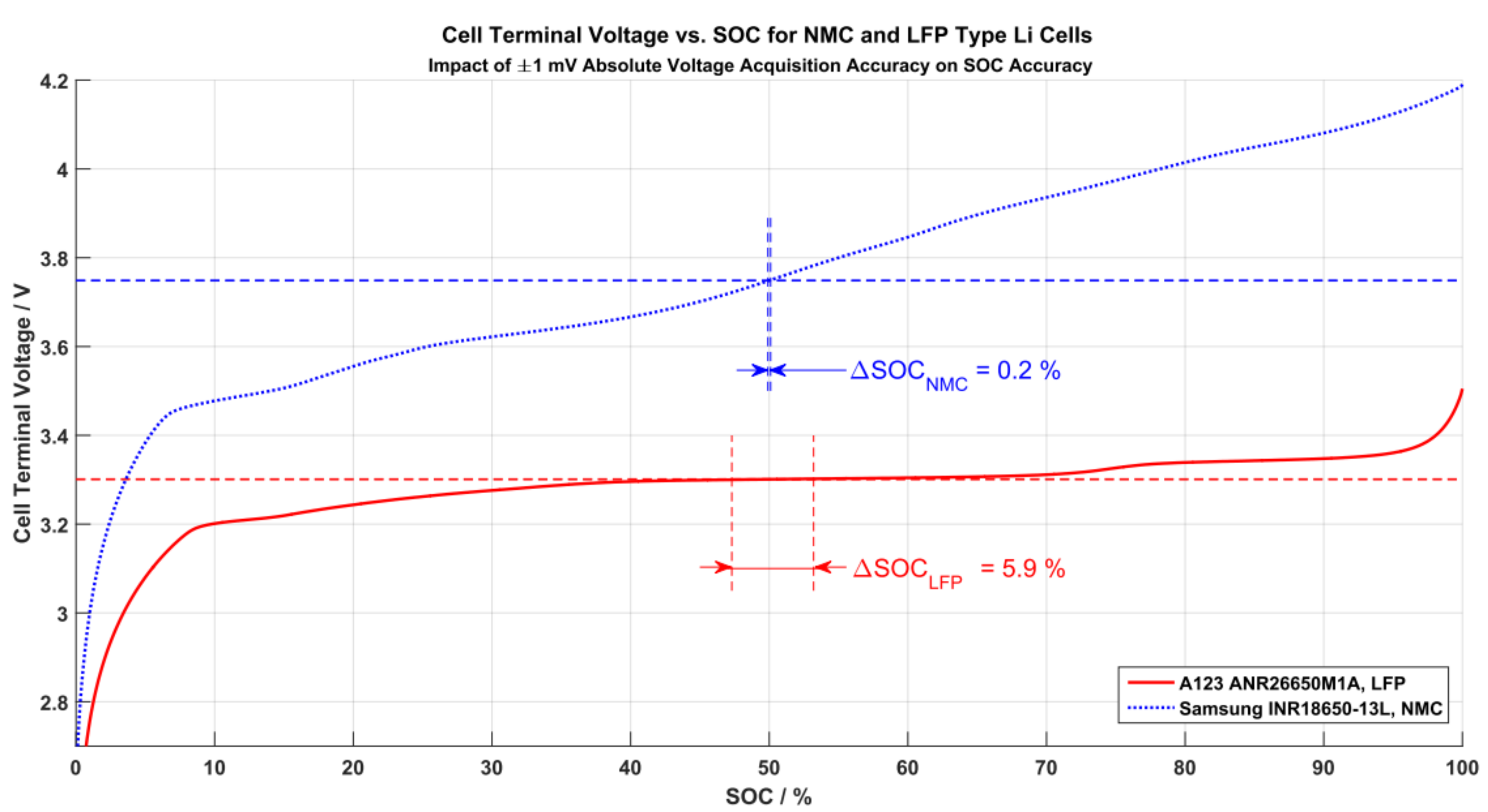
2.2. Voltage Acquisition
- The better the voltage accuracy, the better the SOC estimation.
- Using only voltage data to determine a cell’s SOC might not be sufficient.
2.3. Current Acquisition
2.4. Communication
2.5. Electromagnetic Interference
2.6. Contactors
2.7. Redundancy
2.8. Galvanic Isolation
2.9. Balancing
2.10. Other Requirements
3. Topologies of BMS
3.1. Modularization
3.2. Communication and Data Transfer
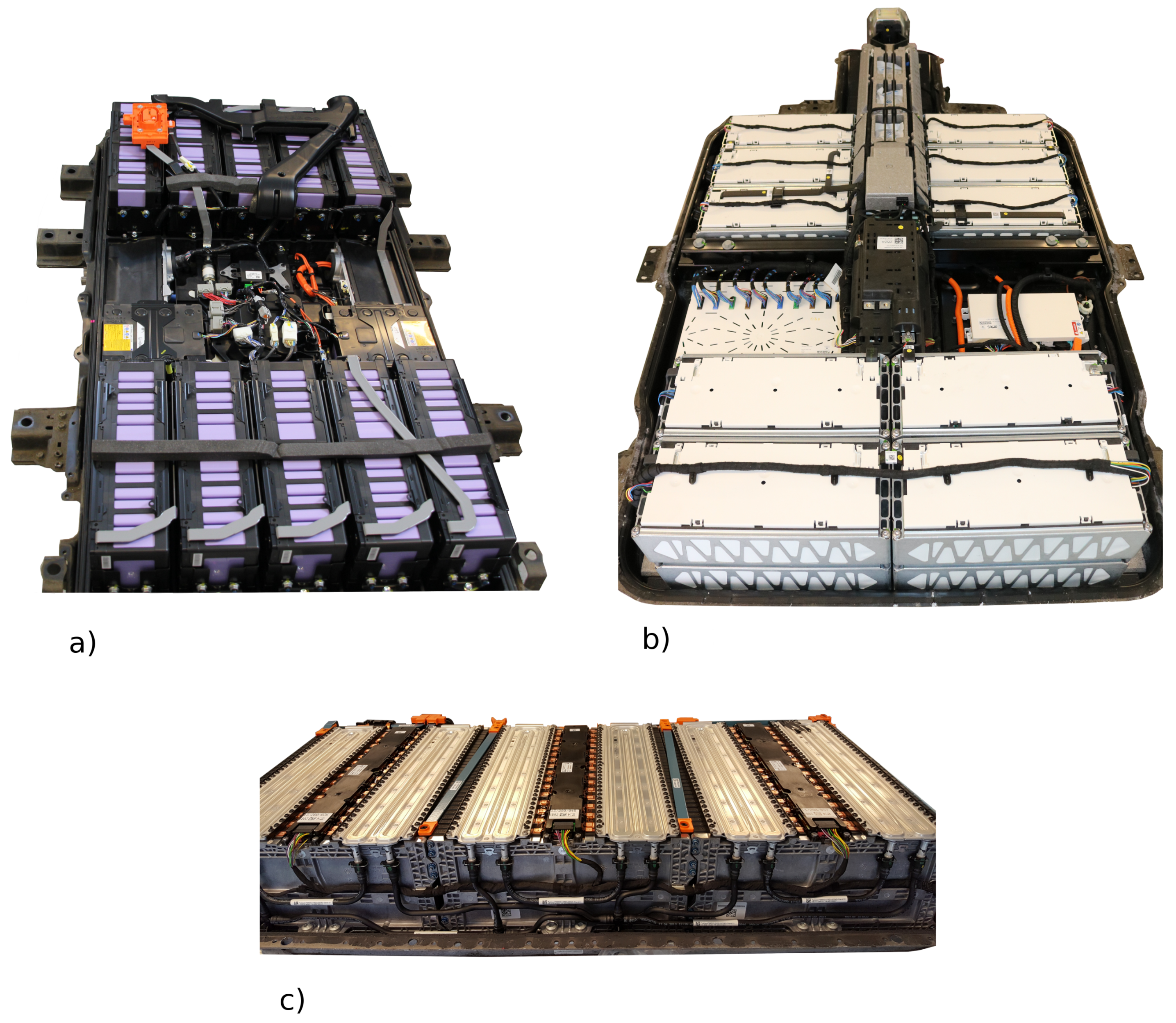
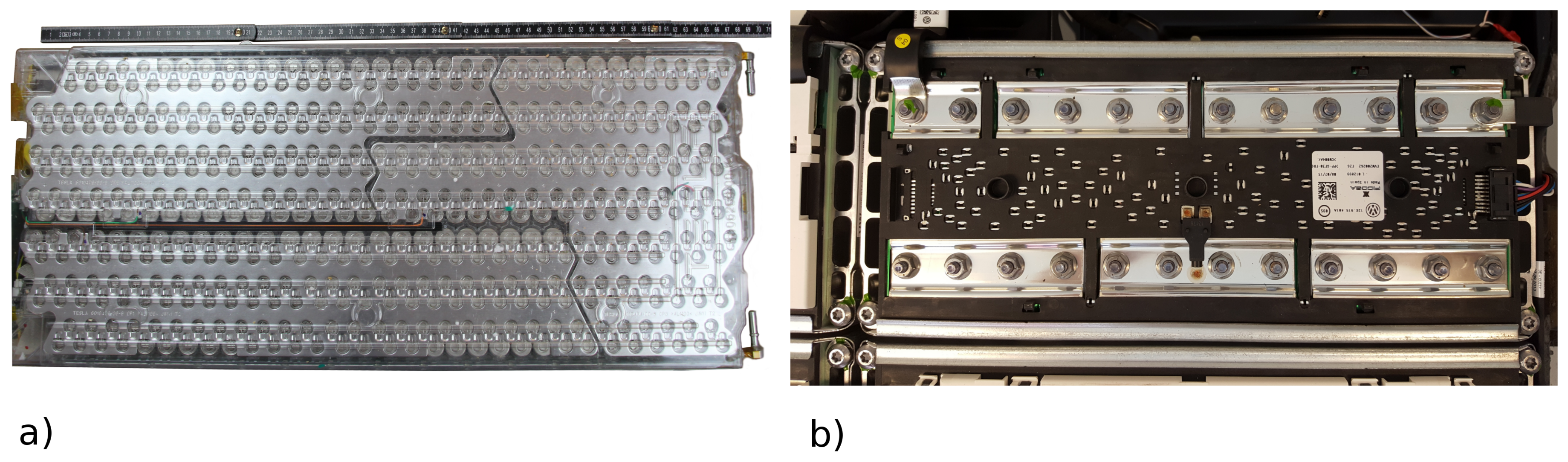
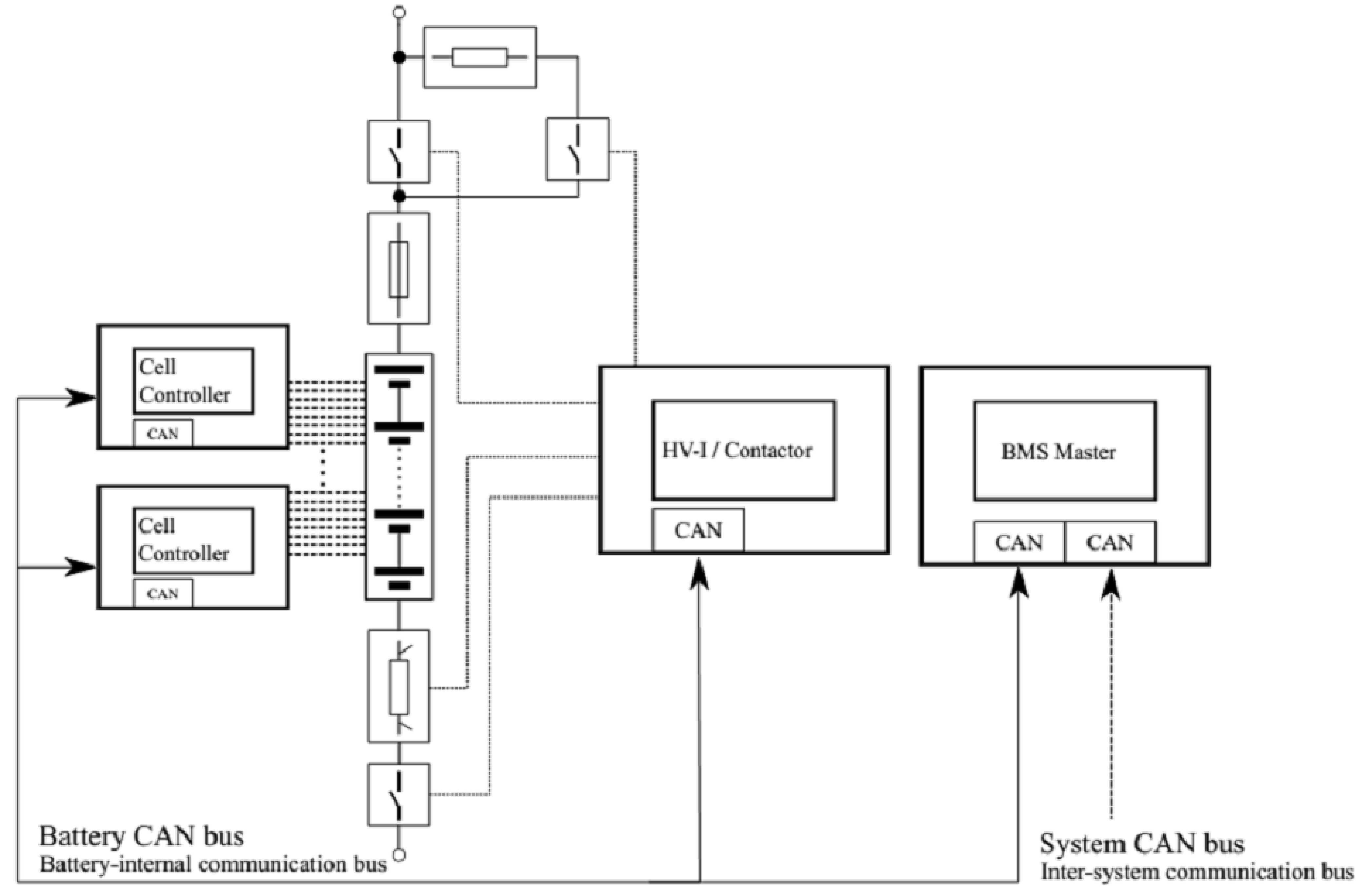
3.3. Real-World Examples
4. Measurement
4.1. Current Measurement
4.1.1. Shunt Resistor
Low-Side vs. High-Side Measuring
4.1.2. Contactless Current Sensors
4.2. Voltage Measurement
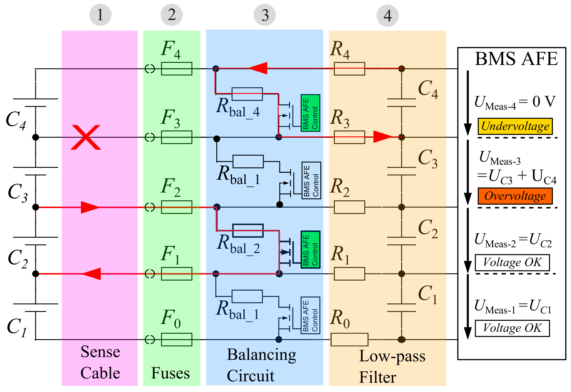
4.2.1. Cell Voltage Measurement
4.2.2. Pack Voltage Measurement
4.3. Temperature Measurement
4.4. Data Transfer
5. Balancing
6. Safety and Reliability
6.1. Insulation Measurement
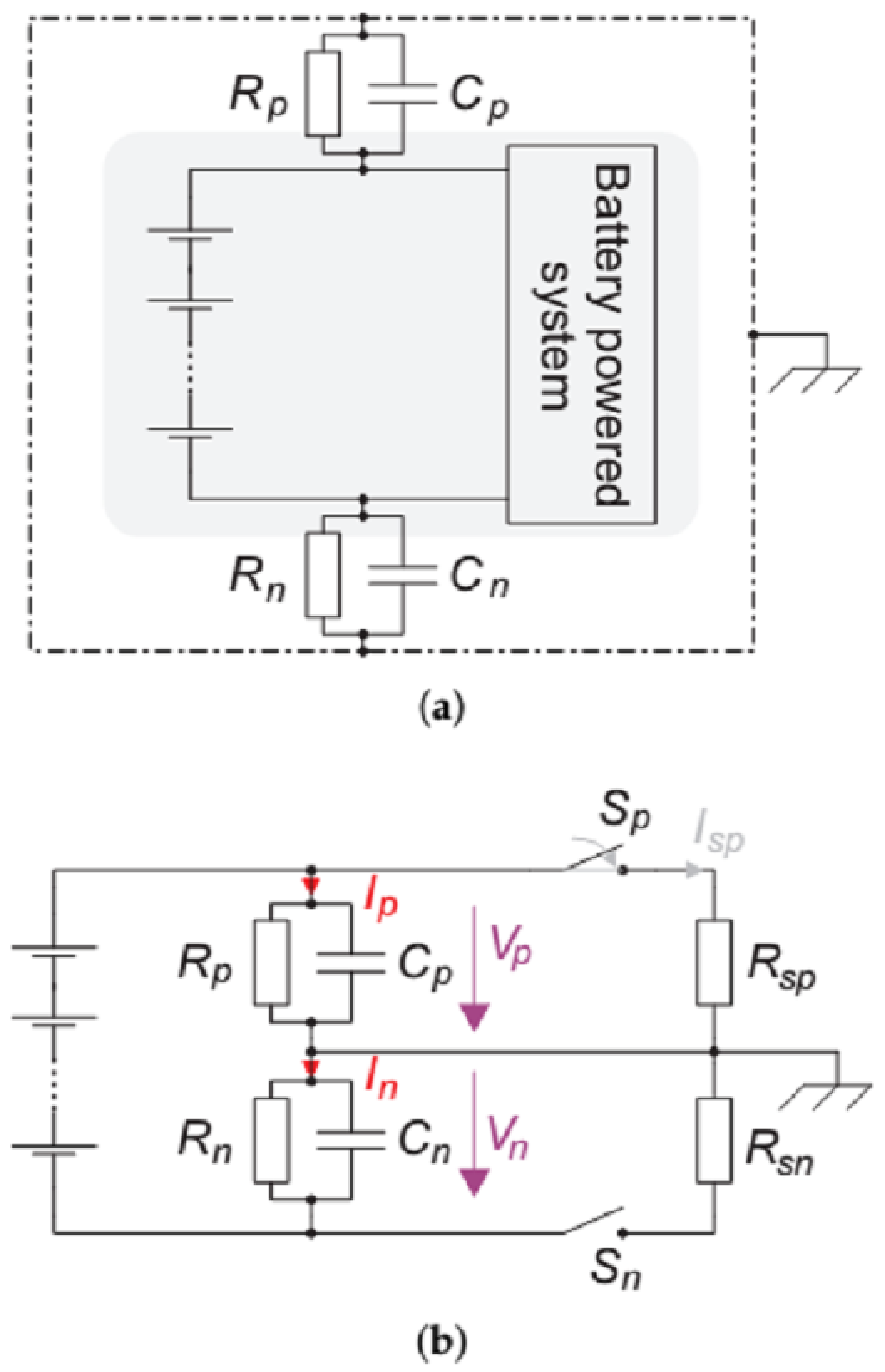
6.1.1. Measurement Method
6.1.2. Minimum Insulation Resistance
7. Conclusions
Supplementary Materials
Acknowledgments
Author Contributions
Conflicts of Interest
Abbreviations
| AC | Alternating Current |
| ADC | Analog Digital Converter |
| AFE | Analog Frontend |
| ASIC | Application-specific integrated circuit |
| BMS | battery management system |
| BMU | Battery Management Unit |
| CAN | Controller Area Network |
| CMU | Cell Management Unit |
| CTV | Cell Terminal Voltage |
| DC | Direct Current |
| ECU | Electronic Control Unit |
| EMI | Electromagnetic interference |
| ESA | European Space Agency |
| EV | Electric Vehicle |
| IC | Integrated Circuit |
| LIN | Local Interconnect Network |
| NTC | Negative Temperature Coefficient |
| OCV | Open Circuit Voltage |
| PCB | Printed Circuit Board |
| PTC | Positive Temperature Coefficient |
| SOC | State of Charge |
| SOF | State of Function |
| SOH | State of Health |
| SPI | Serial Peripheral Interface |
| VCU | Vehicle Control Unit |
| LFP | Lithium Iron Phosphate |
| NMC | Lithium Nickel Manganese Cobalt Oxide |
Appendix A. Mentioned BMS ICs and Similar Devices

| Manufacturer | Name | Mentioned | Automotive | Cells (Max) | Temp. Channels | Ref. |
|---|---|---|---|---|---|---|
| AMS | AS8506C | X | No | 7 | 2 | [26] |
| Analog Devices (Linear Technologies) | LTC6801 | X | Yes | 12 | 2 | [45] |
| Analog Devices (Linear Technologies) | LTC6802-1 | Yes | 12 | 2 | [48] | |
| Analog Devices (Linear Technologies) | LTC6802-2 | X | Yes | 12 | 2 | [25] |
| Analog Devices (Linear Technologies) | LTC6803-1/LTC6803-3 | Yes | 12 | 2 | [49] | |
| Analog Devices (Linear Technologies) | LTC6803-2/LTC6803-4 | Yes | 12 | 2 | [50] | |
| Analog Devices (Linear Technologies) | LTC6804-1/LTC6804-2 | X | Yes | 12 | 5 | [42] |
| Analog Devices (Linear Technologies) | LTC6811-1/LTC6811-2 | X | Yes | 12 | 5 | [28] |
| Maxim IC | MAX11068 | X | Yes | 12 | 2 | [3] |
| Maxim IC | MAX11080/1 | Yes | 12 | 0 | [8] | |
| Maxim IC | MAX17048/MAX17049 | X | No | 1 2 | 0 | [2] |
| Maxim IC | MAX17843 | X | Yes | 12 | 2 | [44] |
| Maxim IC | MAX17830 1 | ? | 12 | ? | [88] | |
| Maxim IC | MAX17823 2 | X | Yes | 12 | ? | [89] |
| Renesas (Intersil) | ISL78600 | Yes | 12 | 4 | [43] | |
| Renesas (Intersil) | ISL78610 | Yes | 12 | 4 | [90] | |
| Texas Instruments | BQ27220 | X | No | 1 | 1 | [1] |
| Texas Instruments | BQ76PL455-Q1 | X | Yes | 16 | 8 | [27] |
| Texas Instruments | BQ76PL536A-Q1 | X | Yes | 6 | 2 | [9] |
References
- Texas Instruments. bq27220 Single-Cell CEDV Fuel Gauge. 2016. Available online: http://www.ti.com/lit/ds/symlink/bq27220.pdf (accessed on 7 January 2018).
- Maxim Integrated. MAX17048/MAX17049 Micropower 1-Cell/2-Cell Li+ ModelGauge ICs. 2014. Available online: https://datasheets.maximintegrated.com/en/ds/MAX17048-MAX17049.pdf (accessed on 2 June 2017).
- Maxim Integrated. MAX11068 12-Channel, High-Voltage Sensor, Smart Data-Acquisition Interface. 2010. Available online: http://media.digikey.com/pdf/Data%20Sheets/Maxim%20PDFs/MAX11068.pdf (accessed on 13 January 2018).
- Pettinger, K.; Koch, G. Lecture Notes Energiespeicher IV; Hochschule Landshut: Landshut, Germany, 2015. [Google Scholar]
- Zeyen, M.G.; Wiebelt, A. Thermisches Management der Batterie. In Handbuch lithium-ionen-Batterien; Korthauer, R., Ed.; Springer: Berlin, Germany, 2013; Chapter 13; pp. 165–174. [Google Scholar]
- Ecker, M.; Sabet, P.S.; Sauer, D.U. Influence of operational condition on lithium plating for commercial lithium-ion batteries—Electrochemical experiments and post-mortem-analysis. Appl. Energy 2017, 206, 934–946. [Google Scholar] [CrossRef]
- Muratori, M. Thermal Characterization Of lithium-ion Battery Cell. Ph.D Thesis, Politechnico Di Milano University, Milan, Italy, 2009. [Google Scholar]
- Maxim Integrated. 12-Channel, High-Voltage Battery-Pack Fault Monitors. 2010. Available online: https://datasheets.maximintegrated.com/en/ds/MAX11080-MAX11081.pdf (accessed on 13 January 2018).
- Texas Instruments. BQ76PL536A-Q1 3 to 6 Series Cell lithium-ion Battery Monitor and Secondary Protection IC for EV & HEV Applications. 2016. Available online: http://www.ti.com/lit/ds/symlink/bq76pl536a-q1.pdf (accessed on 7 January 2018).
- Ziegler, S.; Woodward, R.C.; Ho-Ching Iu, H.; Lawrence, J.B. Current Sensing Techniques: A Review. IEEE Sens. J. 2009, 9, 354–376. [Google Scholar] [CrossRef]
- Marien, J.; Stäb, H. Sensorik/Messtechnik. In Handbuch lithium-ionen-Batterien; Korthauer, R., Ed.; Springer: Berlin, Germany, 2013; Chapter 11; pp. 131–139. [Google Scholar]
- Waag, W.; Fleischer, C.; Sauer, D.U. Critical review of the methods for monitoring of lithium-ion batteries in electric and hybrid vehicles. J. Power Sources 2014, 258, 321–339. [Google Scholar] [CrossRef]
- International Organization for Standardization, Geneva, Switzerland. Road Vehicles—Electrical Disturbances from Conduction and Coupling (ISO Standard No. 7637-1), 2002.
- Guery, J.P.; Mertz, J.L.; Olifant, J. Electric Circuit-Breaker of the Magnetic Arc Extinction Type. US Patent US537,3273, 13 December 1994. [Google Scholar]
- Gigavac. GX16 600+ Amp 12-800 Vdc Contactor. 2015. Available online: http://www.gigavac.com/sites/default/files/catalog/spec_sheet/gx16.pdf (accessed on 7 January 2017).
- Faul, H.J.; Ramer, S.; Eckel, M. Relais, Kontaktoren, Kabel und Steckverbinder. In Handbuch lithium-ionen-Batterien; Korthauer, R., Ed.; Springer: Berlin, Germany, 2013; Chapter 12; pp. 141–163. [Google Scholar]
- International Organization for Standardization. Road Vehicles—Functional Safety (ISO Standard No. 26262); International Organization for Standardization: Geneva, Switzerland, 2011. [Google Scholar]
- Low, H. Hercules MCUs for Use in Electrical Vehicle Battery Management System. Technical Report. 2016. Available online: http://www.ti.com/lit/wp/spny011/spny011.pdf (accessed on 4 November 2017).
- Alvarez, J.M.; Sachenbacher, M.; Ostermeier, D.; Stadlbauer, H.J.; Hummitzsch, U.; Alexeev, A. D6.1—Analysis of the State of the Art on BMS. Technical Report. 2017. Available online: http://everlasting-project.eu/wp-content/uploads/2016/11/EVERLASTING_D6.1_final_20170228.pdf (accessed on 4 November 2017).
- Jensen, H.; Laursen, J. Power Conditioning Unit for Rosetta/Mars Express. Space Power 2002, 502, 249. [Google Scholar]
- Slimm, M.; Spurrett, R.; Thwaite, C.; Lizius, D. lithium-ion Batteries for Space. Space Power 2002, 502, 477. [Google Scholar]
- McKissock, B.; Loyselle, P.; Vogel, E. Guidelines on lithium-ion Battery Use in Space Applications; Technical Report NASA/TM-2009-215751 NESC-RP-08-75/06-069-I; NASA, Glenn Research Center: Cleveland, OH, USA, 2009.
- Baumhöfer, T.; Bruehl, M.; Rothgang, S.; Sauer, D.U. Production caused variation in capacity aging trend and correlation to initial cell performance. J. Power Sources 2014, 247, 332–338. [Google Scholar] [CrossRef]
- Landgraf, J.; Schüssler, M.; Allmann, C. (Eds.) Forschungsprojekt e Performance: Modularer Systembaukasten für Elektrifizierte Fahrzeuge; Cuvillier Verlag: Göttingen, Germany, 2014; ISBN 978-3-95404-526-6. [Google Scholar]
- Linear Technology. LTC6802-2 Multicell Addressable Battery Stack Monitor. 2009. Available online: http://cds.linear.com/docs/en/datasheet/68022fa.pdf (accessed on 13 January 2018).
- AMS. AS8506C Battery Cell Monitor and Balancer IC. 2014. Available online: https://ams.com/ger/content/download/476603/1402377/file/AS8506C_Datasheet_EN_v1.pdf (accessed on 13 January 2018).
- Texas Instruments. bq76PL455A-Q1 16-Cell EV/HEV Integrated Battery Monitor and Protector. 2015. Available online: http://www.ti.com/lit/ds/symlink/bq76pl455a-q1.pdf (accessed on 18 November 2017).
- Linear Technologies. LTC6811-1/LTC6811-2 Multicell Battery Monitors. 2016. Available online: http://cds.linear.com/docs/en/datasheet/68111fb.pdf (accessed on 2 October 2017).
- Könekamp, A.; Hennige, V. The Tesla Model S Battery: A Pack Analysis Study. In Proceedings of the Advanced Automotive & Stationary Battery Conference, Mainz, Germany, 26–29 January 2015; pp. 25–28. [Google Scholar]
- Mitsubishi. Mitsubishi i-MiEV Service Manual, Technical Report. 2010; (OEM Software, not publicly available).
- Pettigrew, W. Selecting the Most Effective Current Sensing Technology. Power Electron. Eur. 2007, 8, 27–31. [Google Scholar]
- Sensitec. CDS4150 MagnetoResistive Current Sensor. Technical Report. 2016. Available online: https://www.sensitec.com/fileadmin/sensitec/Service_and_Support/Downloads/Data_Sheets/CDS4000/SENSITEC_CDS4150_DSE_10.pdf (accessed on 25 October 2017).
- LEM. Automotive Current Transducer Fluxgate Technology, CAB 300-C/SP2. Technical Report. 2015. Available online: http://www.lem.com/docs/products/cab_300-c_sp2.pdf (accessed on 25 October 2017).
- Lerch, R. Elektrische Messtechnik, 6th ed.; Springer Vieweg: Berlin, Germany, 2012; ISBN 978-3-642-22608-3. [Google Scholar]
- Honeywell. Bipolar, Latching, or Unipolar Digital Hall-effect Sensor ICs: SS400 Series, SS500 Series. Technical Report. 2017. Available online: https://sensing.honeywell.com/honeywell-sensing-hall-effect-digital-position-ics-ss400-series-ss500-series-datasheet-32320997-b-en.pdf (accessed on 7 January 2018).
- LEM. Automotive Current Transducer Open Loop Technology HAH1BV 2017. Available online: http://www.lem.com/docs/products/hah1bv_sd24.pdf (accessed on 18 November 2017).
- Allegro. A1363 Low Noise, High Precision, Programmable Linear Hall Effect Sensor IC With Advanced Temperature Compensation and High Bandwidth (120 kHz) Analog Output. 2015. Available online: http://www.allegromicro.com/~/media/Files/Datasheets/A1363-Datasheet.ashx (accessed on 7 January 2018).
- LEM. Current Transducer LTC200-S. 2014. Available online: http://www.lem.com/docs/products/ltc_200-s_sp1.pdf (accessed on 7 January 2018).
- Fabian Luttenberger, A.L.G. Electric Components in Automotive Battery Systems Above 800 V; Battery Power (Kraftwerk Batterie): Essen, Germany, 2017. [Google Scholar]
- United Nations Economic Commission for Europe (UNECE), Uniform Provisions Concerning the Approval of Vehicles with Regard to Specific Requirements for the Electric Power Train (ECE-R100 Rev. 2). 2013. Available online: https://www.unece.org/fileadmin/DAM/trans/main/wp29/wp29regs/2013/R100r2e.pdf (accessed on 7 January 2017).
- Hauser, A.; Kuhn, R. High-voltage battery management systems (BMS) for electric vehicles. In Advances in Battery Technologies for Electric Vehicles; Scrosati, B., Garche, J., Tillmetz, W., Eds.; Elsevier: Amsterdam, The Netherlands, 2015; Chapter 11; pp. 265–281. ISBN 978-1-78242-377-5. [Google Scholar]
- Linear Technologies. LTC6804-1/LTC6804-2 Multicell Battery Monitors. 2014. Available online: http://cds.linear.com/docs/en/datasheet/680412fc.pdf (accessed on 18 November 2017).
- Intersil. ISL78600 Multi-Cell Li-Ion Battery Manager. 2017. Available online: https://www.intersil.com/content/dam/Intersil/documents/isl7/isl78600.pdf (accessed on 18 November 2017).
- Maxim Integrated. MAX17843 12-Channel, High-Voltage Smart Sensor Data-Acquisition Interface. Website Announcement. 2018. Available online: https://www.maximintegrated.com/en/products/power/battery-management/MAX17843.html (accessed on 7 January 2018).
- Linear Technologies. LTC6801 An Independent Multicell Battery Stack Fault Monitor. 2015. Available online: http://cds.linear.com/docs/en/datasheet/68021fa.pdf (accessed on 26 November 2017).
- Maxim Integrated. Robust Bms Solution. Product Line Card. 2014. Available online: https://www.maximintegrated.com/content/dam/files/design/technical-documents/product-brief/BMS-product-brief.pdf (accessed on 7 January 2018).
- Tietze, U.; Schenk, C.; Gamm, E. Halbleiter-Schaltungstechnik, 14th ed.; Springer: Berlin, Germany, 2012; ISBN 978-3-642-31025-6. [Google Scholar]
- Linear Technology. LTC6802-1 Multicell Battery Stack Monitor. 2009. Available online: http://cds.linear.com/docs/en/datasheet/68021fa.pdf (accessed on 26 November 2017).
- Linear Technologies. LTC6803-1/LTC6803-3 Multicell Battery Monitor. 2012. Available online: http://cds.linear.com/docs/en/datasheet/680313fa.pdf (accessed on 26 November 2017).
- Linear Technologies. LTC6803-2/LTC6803-4 Multicell Battery Monitor. 2012. Available online: http://cds.linear.com/docs/en/datasheet/680324fa.pdf (accessed on 26 November 2017).
- Maxim Integrated. DS18B20. 2015. Available online: https://datasheets.maximintegrated.com/en/ds/DS18B20.pdf (accessed on 7 January 2018).
- Texas Instruments. TMP10x Temperaturesensor with I2c and SMBus Interface with Alert Function in SOT-23 Package. 2015. Available online: http://www.ti.com/lit/ds/symlink/tmp100.pdf (accessed on 7 January 2017).
- Texas Instruments. LM75x Digital Temperature Sensor and Thermal Watchdog with Two-Wire Interface. 2015. Available online: http://www.ti.com/lit/ds/symlink/lm75b.pdf (accessed on 7 January 2018).
- LIN Consortium. LIN Specification Package, Revision 2.2A. 2010. Available online: http://vector.com/portal/elemente/lizenz_download/LIN/file.php (accessed on 13 September 2017).
- Shang, Y.; Zhang, C.; Cui, N.; Guerrero, J.M. A Cell-to-Cell Battery Equalizer With Zero-Current Switching and Zero-Voltage Gap Based on Quasi-Resonant LC Converter and Boost Converter. IEEE Trans. Power Electron. 2015, 30, 3731–3747. [Google Scholar] [CrossRef]
- Schmidt, J.P.; Weber, A.; Ivers-Tiffée, E. A novel and fast method of characterizing the self-discharge behavior of lithium-ion cells using a pulse-measurement technique. J. Power Sources 2015, 274, 1231–1238. [Google Scholar] [CrossRef]
- Sinhuber, P.; Sauer, D.U. Analysis of Cell Balancing to improve Performance and Life Expectancy for Lithium-Ion Energy Storage Systems. Poster Session Presented at the 9th International Advanced Automotive Battery & EC Capacitor Conference, Long Beach, CA, USA, 8–12 June 2009. [Google Scholar]
- Gallardo-Lozano, J.; Romero-Cadaval, E.; Milanes-Montero, M.I.; Guerrero-Martinez, M.A. Battery equalization active methods. J. Power Sources 2014, 246, 934–949. [Google Scholar] [CrossRef]
- Rosewater, D.; Williams, A. Analyzing system safety in lithium-ion grid energy storage. J. Power Sources 2015, 300, 460–471. [Google Scholar] [CrossRef]
- International Electrotechnical Commission. Information Technology Equipment—Safety—Part 1: General Requirements (IEC Standard No. 60950); International Electrotechnical Commission: Geneva, Switzerland, 2005. [Google Scholar]
- International Electrotechnical Commission. Safety Requirements for Electrical Equipment for Measurement, Control, and Laboratory Use—Part 1: General Requirements (IEC Standard No. 61010); International Electrotechnical Commission: Geneva, Switzerland, 2012. [Google Scholar]
- Kamath, A.S.; Soundarapandian, K. High-Voltage Reinforced Isolation: Definitions and Test Methodologies: Application Note. Available online: http://www.ti.com/lit/wp/slyy063/slyy063.pdf (accessed on 22 March 2017).
- Isolator vs. Optocoupler Technology: Whitepaper. Available online: http://www.silabs.com/whitepapers/isolator-vs-optocoupler-technology (accessed on 22 March 2017).
- Raijmakers, L.; Danilov, D.L.; van Lammeren, J.; Lammers, M.; Notten, P. Sensorless battery temperature measurements based on electrochemical impedance spectroscopy. J. Power Sources 2014, 247, 539–544. [Google Scholar] [CrossRef]
- Srinivasan, R.; Carkhuff, B.G.; Howeverler, M.H.; Baisden, A.C. Instantaneous measurement of the internal temperature in lithium-ion rechargeable cells. Electrochim. Acta 2011, 56, 6198–6204. [Google Scholar] [CrossRef]
- Becker, J.; Lelie, M.; Jansen, M.; Sauer, D.U. Impact of low Temperatures on Performance and Ageing of lithium-ion Batteries and Strategies for Heating. In Proceedings of the 11th Symposium on Hybrid and Electric Vehicles, Braunschweig, Germany, 18–19 February 2014. [Google Scholar]
- Nordmann, H.; Frisch, M.; Sauer, D.U. Thermal Fault-Detection Method and Analysis of Peripheral Systems for Large Battery Packs. EES J. Meas. 2017, 114, 484–491. [Google Scholar] [CrossRef]
- Institute of Electrical and Electronics Engineers. IEEE Guide for the Protection of Stationary Battery Systems; Institute of Electrical and Electronics Engineers: New York, NY, USA, 1998. [Google Scholar]
- Hendricks, C.; Williard, N.; Mathew, S.; Pecht, M. A failure modes, mechanisms, and effects analysis (FMMEA) of lithium-ion batteries. J. Power Sources 2015, 297, 113–120. [Google Scholar] [CrossRef]
- Brand, M.; Glaser, S.; Geder, J.; Menacher, S.; Obpacher, S.; Jossen, A.; Quinger, D. Electrical safety of commercial Li-ion cells based on NMC and NCA technology compared to LFP technology. In Proceedings of the 2013 World Electric Vehicle Symposium and Exhibition (EVS27), Barcelona, Spain, 17–20 November 2013; pp. 1–9. [Google Scholar]
- Ouyang, M.; Zhang, M.; Feng, X.; Lu, L.; Li, J.; He, X.; Zheng, Y. Internal short circuit detection for battery pack using equivalent parameter and consistency method. J. Power Sources 2015, 294, 272–283. [Google Scholar] [CrossRef]
- McCoy, C.H. System and Methods for Detection of Internal Shorts in Batteries. US Patent US 20140266229 A1, 18 September 2014. [Google Scholar]
- Nordmann, H.; Schaeper, C.; Sauer, D.U. Using a Passive PWM Pattern Balancing Method to Increase Safety in Large Multi-Cell Battery Packs. In Proceedings of the Advanced Automotive Batteries Conference (AABC), Orlando, FL, USA, 6–10 February 2012. [Google Scholar]
- Nordmann, H.; Zappen, H.; Sauer, D.U. Verfahren zur Bestimmung der Zuleitungsimpedanz in Mehrzelligen Batteriepacks zur Leitungsfehlererkennung. DE Patent DE102013013471A1, 19 February 2015. [Google Scholar]
- Liu, Z.; Ahmed, Q.; Zhang, J.; Rizzoni, G.; He, H. Structural analysis based sensors fault detection and isolation of cylindrical lithium-ion batteries in automotive applications. Control Eng. Pract. 2016, 52, 46–58. [Google Scholar] [CrossRef]
- Yin, G.; Liu, Y.; Xu, H.; Li, M. The New DC System Insulation Monitoring Device based on Phase Differences of Magnetic Modulation. In Proceedings of the International Conference on Systems and Informatics (ICSAI), Yantai, China, 19–20 May 2012. [Google Scholar]
- Li, J.; Wu, Z.; Fan, Y. Research on Insulation Resistance On-Line Monitoring for Electric Vehicle. In Proceedings of the Eighth International Conference on Electrical Machines and Systems, Nanjing, China, 27–29 September 2005. [Google Scholar]
- Jiang, J.; Ji, H. Study of Insulation Monitoring Device for DC System Based on Multi-switch Combination. In Proceedings of the 2009 Second International Symposium on Computational Intelligence and Design, Changsha, China, 12–14 December 2009; pp. 429–433. [Google Scholar]
- Zhen-jun, W.; Li-fang, W. A Novel Insulation Resistance Monitoring Device for Hybrid Electric Vehicle. In Proceedings of the 2008 IEEE Vehicle Power and Propulsion Conference, Harbin, China, 3–5 September 2008. [Google Scholar]
- Van Vugt, P.; Bijman, R. Impact of Grounding and Filtering on Power Insulation Monitoring in Insulated Terrestrial Power Networks. In Proceedings of the 2013 International Symposium on Electromagnetic Compatibility (EMC EUROPE), Brugge, Belgium, 2–6 September 2013. [Google Scholar]
- United Nations Economic Commission for Europe (UNECE), Geneva. ECE/TRANS/WP.29/2010/52. 2010. Available online: https://www.unece.org/fileadmin/DAM/trans/doc/2010/wp29/ECE-TRANS-WP29-2010-52e.pdf (accessed on 13 January 2018).
- International Organization for Standardization. ISO 6469-1 Electrically Propelled Road Vehicles—Safety Specifications; (ISO Standard No. 6469-1); International Organization for Standardization: Geneva, Switzerland, 2009. [Google Scholar]
- DIN Deutsches Institut für Normung e. V. DIN EN 61557-8 Elektrische Sicherheit in Niederspannungsnetzen bis AC 1000 V und DC 1500 V; DIN Deutsches Institut für Normung e. V.: Berlin, Germany, 2015. [Google Scholar]
- Group, Chauvin Arnoux. Insulation Resistance Testing Guide. 2010. Available online: http://www.chauvin-arnoux.com/sites/default/files/D00VEC36.PDF (accessed on 7 January 2017).
- Lelie, M.; Sauer, D.U. Approach to a “Wireless”, Cell Integrated Battery Management System. In Proceedings of the Kraftwerk Batterie—Advanced Battery Power Conference 2016, Münster, Germany, 25–27 April 2016. [Google Scholar]
- Bolsinger, C.; Brix, J.; Dragan, M. High Frequency Model of lithium-ion Batteries for Powerline Communication. In Proceedings of the Kraftwerk Batterie—Advanced Battery Power Conference 2016, Münster, Germany, 25–27 April 2016. [Google Scholar]
- Lorentz, V.; März, M.; Wenger, M. Energiespeicherzelle, Energiespeicherzellenmodul und Trägersubstrat. DE Patent DE201,110,088,440, 21 January 2010. [Google Scholar]
- Maxim Integrated. 12-Channel, High-Voltage Battery Sensor with Advanced SMBus Ladder and External Cell Balancing. Website Announcement. Available online: https://www.maximintegrated.com/en/products/power/nanopower-dc-dc-regulators/MAX17830.html (accessed on 13 January 2018).
- Maxim Integrated. MAX17823 A 12-Channel, High-Voltage Sensor with Integrated Cell Balancing and Differential UART for Daisy-Chain Communication. Website Announcement. 2016. Available online: https://www.maximintegrated.com/en/products/analog/sensors-and-sensor-interface/MAX17823.html (accessed on 22 August 2016).
- Intersil. ISL78610 Multi-Cell Li-Ion Battery Manager. 2017. Available online: https://www.intersil.com/content/dam/Intersil/documents/isl7/isl78610.pdf (accessed on 18 November 2017).

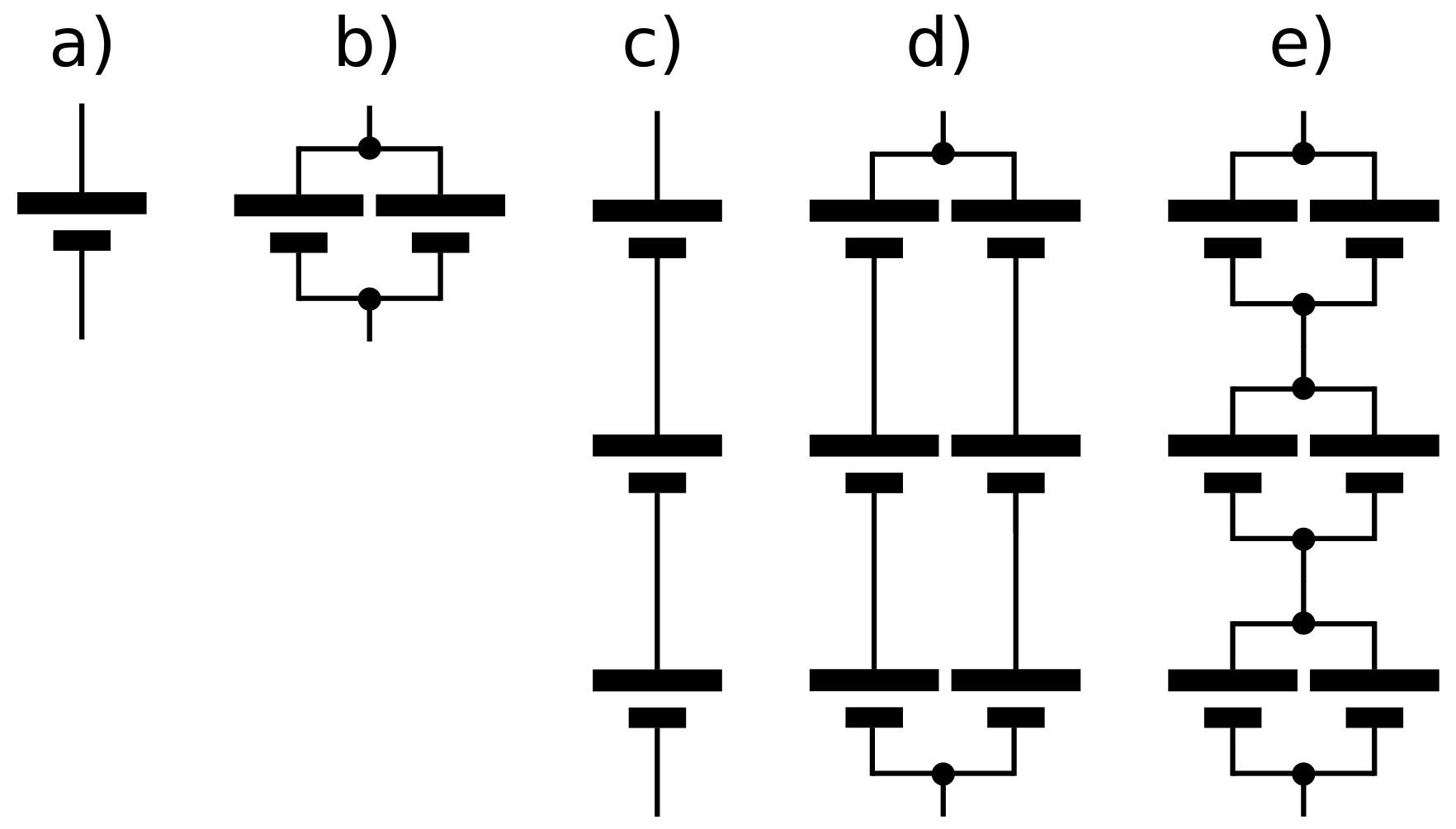


| (a) | (b) | (c) | (d) | (e) | |
|---|---|---|---|---|---|
| Voltage | |||||
| Capacity | |||||
| Voltage channels | 1 | 1 | 3 | 6 | 3 |
© 2018 by the authors. Licensee MDPI, Basel, Switzerland. This article is an open access article distributed under the terms and conditions of the Creative Commons Attribution (CC BY) license (http://creativecommons.org/licenses/by/4.0/).
Share and Cite
Lelie, M.; Braun, T.; Knips, M.; Nordmann, H.; Ringbeck, F.; Zappen, H.; Sauer, D.U. Battery Management System Hardware Concepts: An Overview. Appl. Sci. 2018, 8, 534. https://doi.org/10.3390/app8040534
Lelie M, Braun T, Knips M, Nordmann H, Ringbeck F, Zappen H, Sauer DU. Battery Management System Hardware Concepts: An Overview. Applied Sciences. 2018; 8(4):534. https://doi.org/10.3390/app8040534
Chicago/Turabian StyleLelie, Markus, Thomas Braun, Marcus Knips, Hannes Nordmann, Florian Ringbeck, Hendrik Zappen, and Dirk Uwe Sauer. 2018. "Battery Management System Hardware Concepts: An Overview" Applied Sciences 8, no. 4: 534. https://doi.org/10.3390/app8040534
APA StyleLelie, M., Braun, T., Knips, M., Nordmann, H., Ringbeck, F., Zappen, H., & Sauer, D. U. (2018). Battery Management System Hardware Concepts: An Overview. Applied Sciences, 8(4), 534. https://doi.org/10.3390/app8040534