1. Introduction
The Internet of Things (IoT) environment is expanding in two directions: first, the application of IoT is covering safety-critical operations, where the IoT devices should report correct information and run instantly as instructed (e.g., in smart factory and rescue operations). Second, the number of inter-connected devices in an IoT network rapidly increases. A network of inter-connected devices is called a “swarm” [
1] and the use cases of the swarm is extending to swarm robots, environment monitoring, surveillance systems et al. As the IoT environments evolve, building a trustworthy swarm is getting important, but it is also more challenging than ever; we need a scalable way to check whether every device in a swarm is working correctly. The recent denial of service (DoS) attack on the DynDNS (Domain Name Service) shows how a large number of IoT devices can be easily infected by malware and how much damage the compromised devices can incur to the Internet [
2].
For this purpose, the attestation process is used to check whether devices are working as we intended. Among attestation methods, the remote attestation protocols have focused on checking the integrity of embedded devices. In the remote attestation protocol, a
verifier requests a
prover to prove the integrity of its software and then the prover presents the
measurement of its software to the verifier. If the measurement is valid, the verifier can trust the integrity of the prover. In particular, since the embedded devices in Wireless Sensor Networks (WSN) and IoT are constrained in computational capability and battery powers, the remote attestation on them should be efficient. Conventionally, the hardware or co-processor-based attestation methods [
3,
4,
5,
6,
7,
8] have employed a special-purpose hardware module to build a secure trust anchor for attestation results. However, it requires expensive hardware additions, thus it is not suitable for WSN and IoT devices. In that sense, software-based attestation methods have been proposed [
9,
10,
11,
12], which use the checksum response with tight timeout and require no secure hardware additions. Its practicality, however, was still challenged in the real-world scenarios [
13]. Thus, the hybrid attestation mechanisms applied the cheap hardware components, such as Read-Only Memory (ROM) and Memory Protection Unit (MPU), to build a minimal hardware trust anchor [
14,
15,
16,
17]. The swarm attestation [
18,
19,
20,
21,
22,
23,
24,
25] is based on this approach. It efficiently checks whether a large number of devices are in good software configurations (without any modifications). The methods for swarm attestation have mainly focused on detection of integrity violation of devices with efficiency [
18,
19], DoS-attack resiliency [
22], verifiable aggregation [
21], physical attacks [
20,
23], execution trace [
24] or device property [
25].
However, in the real-world situations, IoT swarms are being faced with more hostile environments than that assumed in the previous approaches. We have already observed the result of the outbreak of large-scale malware (e.g., Mirai Botnet [
2]), where the phenomenon follows the malware-infection epidemic model [
26]. It showed that how fast a group of locally connected devices can be infected at the first stage. The previous methods already provide a way to identify compromised devices during attestation process [
19,
21]. Unfortunately, they are not scalable for such large-scale infections. The overhead caused by indicating compromised devices individually overwhelms the attestation process.
In the view of the network operators, the efficient maintenance is a key to keep a swarm network trustworthy. However, the maintenance supports in the attestation process have not yet been paid attention to enough. Outdated devices are dangerous. Unmanaged devices have been the cause of well known attacks [
27] and its security vulnerabilities are being unceasingly disclosed [
28]. The IoT devices are exposing vulnerabilities from the network stack to the software stack [
29]. A dysfunctional device can cause the failure of a whole IoT-based system. Furthermore, although each device has limited capabilities, recent studies [
30,
31] show that the compromised devices can be organized into a mobile botnet conducting more sophisticated attacks. However, more than 200,000 devices in 2017 still require a software patch against the Heartbleed attack that occurred in 2014 [
32].
Therefore, in this paper, we propose a lightweight attestation method, called “CAMIE,” (Collective Attestation for Manageable IoT Environments) to enhance the scalability of attestation and detection in the hostile environment. We take two factors into account in CAMIE: (1) scalable attestation reporting and (2) regional targeting of devices. A swarm network consists of heterogeneous devices, each of which also has multiple software components. We first devise a tagging mechanism to distinguish devices at the software component level. In the initial stage, a tag is injected into the binary code of a component so that it is bound to the component. The component-binding tag is used for both attestation measuring and component searching. In the attestation phase, a whole swarm network is dissected into regions. A region anchor merges the tag-contained measurement reports of region members into a region summary. Due to the aggregation of the region summary, the verifier can identify the compromised devices or regions even in the contagious malware outbreak. Furthermore, CAMIE uses the swarm network structure to target a device of a specific configuration as well as to attest. The combined process of attestation and targeting can improve the management process for security patching or updating.
Contributions. To sum up, we address that scalability to support the management of a swarm network is required for the attestation process. Thus, we present a lightweight attestation method called CAMIE. It employs a component-bound device tagging to efficiently identify a device or a component in a swarm network. CAMIE is scalable to the large-scale infection. The verifier can identify compromised devices efficiently with the regional information. The proposed system also supports the components or device searching to discover the target region for (on-site) maintenance. Finally, we present the evaluation on the performance of the hybrid attestation approaches against large-scale infection scenarios.
Paper Organization. Our paper is structured as follows.
Section 2 describes the related work on collective attestation.
Section 3 then presents the limitations in previous collective attestations and the overview of
CAMIE. The detailed process of
CAMIE is explained in
Section 4. We also present the extension of
CAMIE for DoS-attack resiliency in
Section 5.
Section 6 analyzes the performance of
CAMIE and compares it to other schemes. Finally, we conclude the paper in
Section 7.
2. Related Work
Attestation for IoT/WSN devices. Attestation has been researched in a number of studies. The research work on attestation can be categorized into three approaches. First, software-based attestation [
9,
10,
11,
12] targets constrained devices especially for the WSN/IoT environment. Under the assumption that forging a result incurs additional computation overhead inevitably, the software-based attestation optimizes the checksum code and then uses the time-based checksum results. This approach is suitable for low-end devices since they require no hardware additions. However, the remote attestation through wireless communications may suffer from various network delay or network failures. Thus, the use of software attestation is limited to the one-hop attestation, which restricts the practical use of attestations [
13]. Second, the co-processor based attestation [
3,
4,
5,
6,
7,
8] lets devices prove their integrity by using the secure result from the security co-processors, i.e., Trusted Platform Module (TPM) [
33]. The security co-processor can guarantee the secure execution of attestation code and generate the machine-unique digital signature on the attestation results. Although the hardware-backed attestation provides the trustworthy results, the cost for the security co-processor is still high for a large-scale WSN/IoT devices. Third, the hybrid approaches [
14,
15,
16,
17] employ the low-cost, simple hardware supports (e.g., ROM and MPU), to reinforce the process of attestation. The read-only attestation code and secure key provide the basic trust base on the attestation, but it obstructs the efficient update process (e.g., OTA software update), and increases the maintenance cost in operation. These approaches apply individual identification to recognize compromised nodes. Thus, when attesting to a large number of devices, the runtime for attestation increases linearly with the number of compromised devices. However, the proposed scheme takes the approach of the collective attestation and coalesced measurement report for scalability.
Collective Attestation. In order to apply attestation to multiple provers, the collective attestation approaches have been proposed in [
18,
19,
20,
21,
22,
23]. SMATT [
18] is the first attempt for attesting multiple provers, and it is proposed for the attestation on smart meters. SMATT assumes that all the devices are identical. It compares the measurement results from randomly sampled devices and then identifies compromised devices that give different results from others. It has been evolved into collective (or swarm) attestation approaches to target a larger number of devices for attestation. Among them, SEDA [
19] and SANA [
21] are closely related to our work. SEDA performs the in-network verification to improve the scalability of attestation. A newly arrived device registers itself to a neighbor with its certificate to prove the software configuration. Like other collective attestation methods, SEDA assumes the minimal trust anchor, such as SMART [
15] and TrustLite [
16], of the hybrid attestation. Upon the attestation request, SEDA builds a spanning tree and reports the result of the integrity checks reversely along the spanning tree. SANA extends the swarm attestation by using Optimistic Aggregate Signature (OAS), which supports aggregation and multi-signatures. SANA uses the spanning tree as the aggregation tree. At the confluence point, the OAS signed reports from provers are aggregated. If a compromised device is found during the process, the aggregator appends the signature of the compromised device to the message. SEDA and SANA provide the mechanism to identify compromised devices at collective attestation, but the individual identification is not scalable to contagious malware infections, of which a large number of infected devices may overwhelm the normal attestation process. In addition, although OAS is much more efficient than the traditional public key cryptography, it still requires a high amount of computation for IoT/WSN devices. Recently, SeED [
22] is proposed to prevent the DoS attack caused by a forged attestation request. SeED uses non-interactive attestation, where the attestation is triggered by a shred timer. However, SeED also requires the additional hardware support of RTC. We extend our protocol against the DoS attack by employing the token system on top of blockchain system. DARPA [
23] and SCAPI [
20] handle the physical attack in attestation. They assume that the physical modification causes unavoidable downtime of the device, thus the absence detection can find the devices under the physical attacks. DARPA sends heartbeat signals to devices to check the absence, and SCAPI regularly updates the session key so that absent device cannot get the newly update key to continue the communication with other devices. We do not assume the physical attacks in
CAMIE, but the region anchor can initiate the absence check.
3. Collective Attestation for Maintenance
In this section, we first present the brief introduction to the swarm attestation and our assumptions on the swarm attestation process. We then present the motivations of this paper by addressing the limitations of the swarm attestations in practical operations. Finally, we give the overview of our approach to extend the swarm attestation to improve both scalability and manageability.
3.1. Swarm/Collective Attestation
The collective or swarm attestation provide a scalable attestation for a large number of devices in a swarm. A swarm consists of inter-connected devices. In the attestation process, the device is a
prover that proves the integrity to a
verifier. A verifier sends a request with a challenge to a prover; then, the prover computes or uses the precomputed
measurement on the device state, such as the program code and the memory contents. The collective attestation extends the one-to-one relationship of the attestation to the one-to-many (a verifier to multiple provers) relationship. SMATT [
18] firstly introduced this approach to check the multiple smart meters, and SEDA [
19] then generalized the process for a swarm network. SEDA uses the in-network attestation. It builds a spanning tree from the attestation initiator. The devices check the integrity of other devices and report back along the spanning tree. SANA [
21] employs the spanning tree as the attestation tree and assigns a role of
aggregator to the device at the confluence points. To aggregate the result, each attestation report is signed by Optimistic Aggregate Signature (OAS). If a compromised node (or a bad prover) is found, SANA cumulatively appends the information on every bad prover and configuration to the attestation results. SEDA also has an extension to keep a list of compromised nodes in the attestation list. There are the more explanations on the collective attestation are in
Section 2.
3.2. Motivations and Goals
To maintain a swarm network trustworthy, the attestation should produce a reliable report even during the time that contagious malware is infecting a number of devices. Enumerating the list of individual compromised devices is not scalable as well as informative for the maintenance, the network operator needs to outline which part of a swarm requires maintenance and which part is still trustworthy. Furthermore, since the maintenance of a swarm inevitably requires a manual or on-site task for software update or device replacement, it may incur long downtime and a high cost. Thus, the maintenance needs to be localized and specified.
Therefore, we propose a new attestation approach CAMIE. Based on the requirements to efficiently manage a swarm, CAMIE presents a secure attestation to achieve the following goals.
Scalable attestation reporting:CAMIE checks the integrity of large-numbered devices and computes a coalesced measurement summary, where the software components information of the compromised devices or search targets are merged. In addition, each region has a region summary distinguishable. Thus, the network operator can outline the status of a whole network and use the information for maintenance.
Attestation with searching and targeting: The attestation process of CAMIE can be also used for searching and targeting devices of a specific software configuration. Due to the dynamics of a swarm and the frequency of critical security updates, the network operator needs to actively and efficiently find devices. CAMIE employs the identification based on component-embedded tags for each device so that it can convert it to a searchable pattern by using the Bloom filter approach. During the attestation, the devices of matched patterns are also reported via the region summary.
3.3. CAMIE Overview
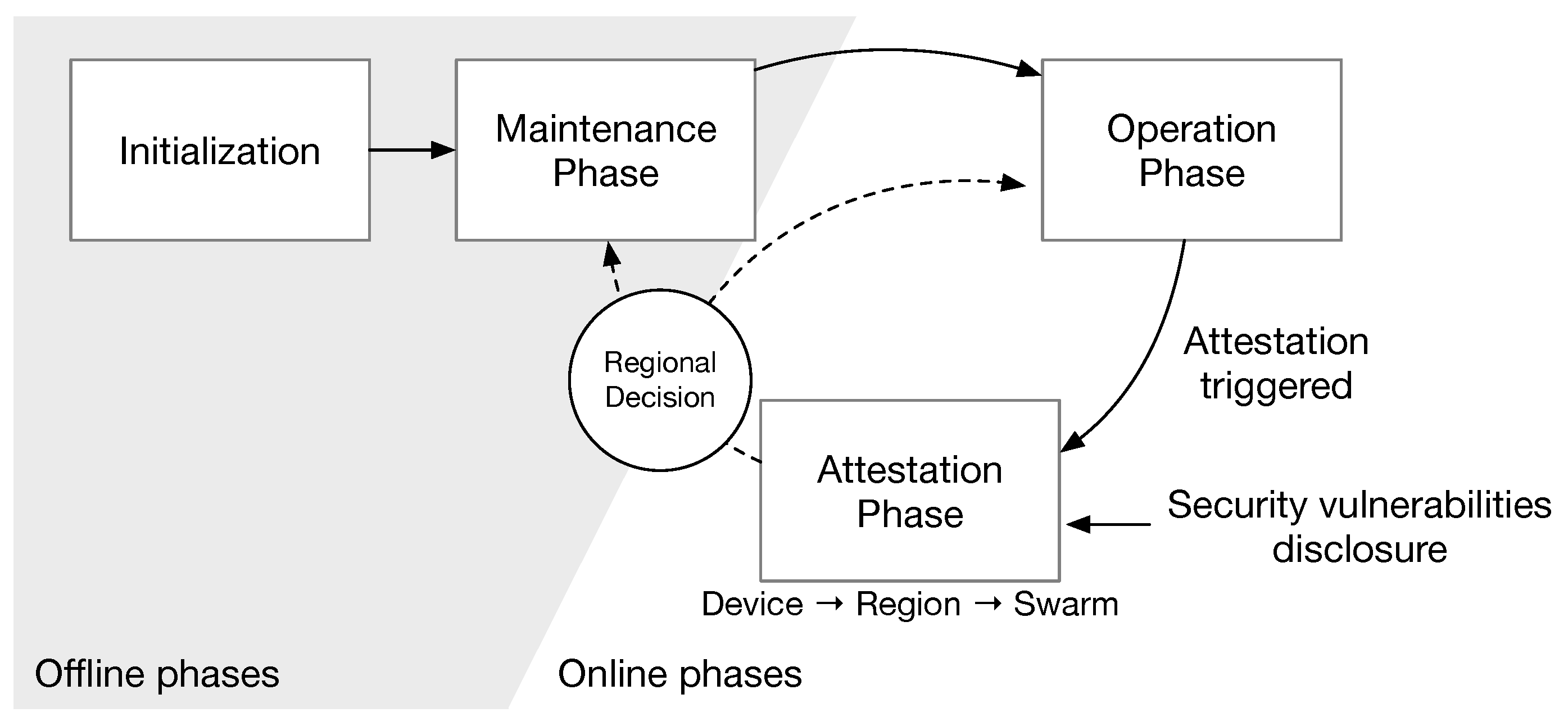
Phases. We define three phases: maintenance, operation, and attestation phases as shown in
Figure 1.
Maintenance phase: The maintenance phase is an offline phase to install/update software and replace devices. Upon initializing a swarm network, the network operator injects a distinguishable tag into every component binary code. It builds a Bloom filter for each component and then joins them into a device tag.
Operation phase: This is the phase for normal operation. In the operation phase, the swarm attestation is prepared in advance. When a new device joins to a swarm, the network operator assigns the device tag to a device and then the device registers its device tag to neighbors. During the operation phase, any authorized verifier requests the swarm attestation.
Attestation phase: Upon the request, the swarm attestation is performed in the attestation phase and reports the attestation results to the verifier. If an erratic (or compromised) device is detected, then the device is marked as a target and its registered tag is merged into the region summary. The region anchor then sends the aggregated tags of targets. CAMIE can be used for target search by adding a target pattern in the joined form of device tags. If a device tag is matched to the target pattern, it is also merged to the region summary. Based on the attestation result, the network operator can decide whether the maintenance phase starts or not. If the maintenance job is required only for specific regions only, then the maintenance can be limited to the part of a swarm while the remaining part keeps working in the operation phase.
Component tags and region anchors. In the swarm attestation, program code itself is protected in the minimal trust anchor of the hybrid attestation, if the binary-embedded component tag can keep the secure binding between a tag and a device, then it be used as a primitive indicator of attestation. First, since a tag is generated from a random number, every tagged component is distinguishable even if it has the same binary code with other components. Second, the device tag is composed by merging (i.e., OR’ing) the Bloom filter of the component binary code. Therefore, in CAMIE, the device tag is the measurement value of the device as well as the fingerprints of the installed software components. The device tag can be used for finding a installed component in the searching process. A region anchor separately attaches the merged device tag of compromised or targeted device up to the point to the attestation result, which is called “region summary.” Hence, the region summary can show the regional information to the verifier and suppress the loss of details in the state merging.
3.4. Notations and Assumptions
Table 1 shows the notations used in this paper. We assume that a swarm consists of heterogeneous devices and each device consists of multiple software components. That is, a device contains a set of software components, each of which is denoted by
. As in SEDA [
19], SANA [
21], and SeED [
22], we also assume that each device has minimal hardware support, which consists of read only memory (ROM) and memory protection unit (MPU), to build the trust anchor by applying such systems as SMART [
15], TrustLite [
16] and TyTAN [
17]. In this paper, we explicitly define a role of the network operator. The network operator is generally a verifier of the attestation. However, the network operator can authorize an external verifier to initiate an attestation request. The network operator also manages a swarm in the maintenance phase.
4. Design
A swarm runs in the phases from the offline phase (the maintenance phase including the initialization), to online phases (the operation phase and the attestation phase). In this section, we also describe the process of CAMIE for each phase in the order.
4.1. Maintenance Phase
In the management phase, the network operator can prepare, update or replace the devices offline. The offline or on-site manual jobs are inevitable to manage swarm networks since the ROM-based minimal hardware anchors prevent the remote over-the-air (OTA) update from covering all the updates. The network operator injects a component tag to each software component and generates a device tag to easily maintain devices.
Component tag. Making every software component distinguishable is helpful to find a compromised component as well as to detect absent (disappeared) devices from the measurement. For this purpose,
CAMIE puts a unique tag within each software component. Once the tag is embedded in the program code, it is protected by the hardware mechanisms of the minimal trust anchor [
15,
16,
17]. If ones store the component tags in a separate storage instead of injecting the tags, it requires an additional process to validate whether the binding between metadata and binary codes are secure, as in property-base attestation [
25]. Thus, we choose the direct tag injection approach.
More formally, when the network operator installs or updates a software component to a device , the network operator newly generates a random value for a tag, for each software component .
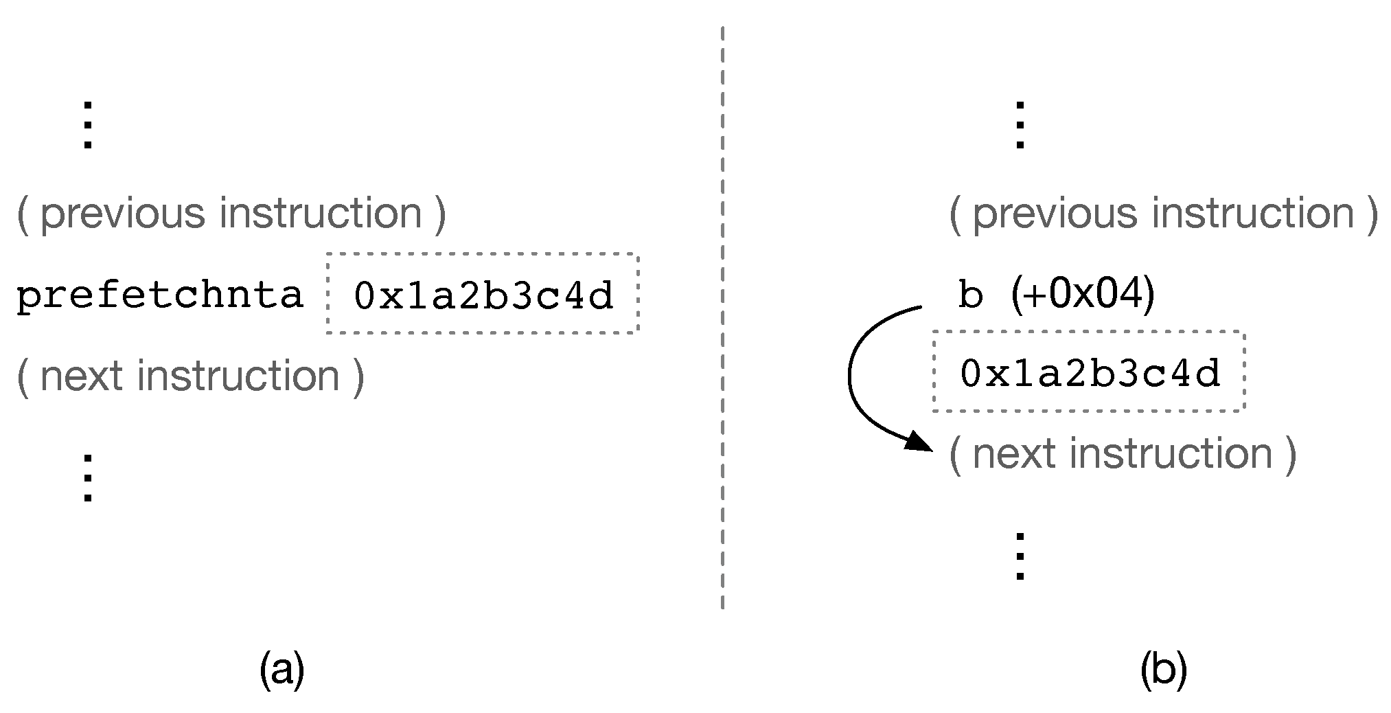
Tag injection. To put a tag in the program code without modifying the program semantics, there are two options: (1) to use the operand of side effect free instructions (e.g.,
prefetchnta in the x86 architecture), and (2) to use a tag with a bypassing branch, which uses a relative-address jump (e.g.,
b in the ARM architecture) to skip the tag.
Figure 2 shows the examples of the two approaches. The former method (
Figure 2a) does not change the control flow graph, which is good for attestation schemes checking control flow (e.g., CFLAT [
24]), but the tag size is limited to the operand size. The latter method (
Figure 2b) may alter the control flow graph, but the tag size is flexible.
Before injecting the tag, the binary code of software component is prepared in either way as shown in
Figure 2. Injecting extra instruction into binary code may break the absolute-address branches by shifting the jump-target address, thus it may require the sophisticated binary rewriting. The network operator can compile the source code to the form of position independent executable (PIE) to minimize the rewriting. More preferably, if source code is available, the network operator can add the tag instructions with a dummy tag as an inline assembly (e.g.,
asm) in source code before compiling it. Since the tag instructions are already in the binary code, binary rewriting is simplified to the replacement of the dummy tag with
.
Device tag ().CAMIE generates the device tag from the tagged software components. From an empty bitvector,
, the network operator computes the Bloom filter (i.e., applying different hash functions) for each software component,
, of a device, and merges it to
by OR’ing. That is,
, where we denote by
bf the Bloom filter operation and
z is the number of installed software components in a device. (The proper length of the bitvector and the number of hashes used in
bf is discussed in
Section 6.2 to suppress excessive false positives.) After assigning
as the device tag to
, the network operator stores a mapping,
, from a device tag to a set of the pairs of the installed software component and its component tag (i.e.,
).
4.2. Operation Phase
In the operation phase, the devices keep updating the list of currently connected neighbors. When a new device joins a swarm, it registers itself via sending a join request to one of its neighbors. As in SEDA [
19], we assume that two neighboring devices
and
establish a pairwise attestation key
and register each other’s device tag,
and
, by key management methods (e.g., [
34]). Thus, the neighbor list
of the device
contains the neighbors that share an attestation key with.
4.3. Attestation Phase
An attestation verifier, which authorized by the network operator (
Section 5), can initiate the attestation phase.
4.3.1. Requests
The network operator or an authorized verifier can initiate the attestation phase by sending the attestation request. CAMIE supports two types of requests: (1) attestation and (2) target search. The measurement on the device is performed for both requests in order to filter out responses from compromised devices. Upon the request, the device first propagates the request message to its neighbors while forming a spanning tree, which is called “attestation tree,” at the same time. Thus, the parameters to describe the attestation tree are included in both requests: a nonce for the request (N), the maximum number of neighbor (), and a summary depth (), which indicates the maximum height of a region. The parameters and control the granularity of region and the coverage of summarized information, respectively. For the attestation request, only these parameters are used, but the request message additionally contains the target pattern for the target search request. Any device of matched to is reported.
A device, , performs the following steps to relay attestation requests:
Store the (received) request parameters N, , , and optionally .
Randomly pick a neighbor a from .
Deliver the request message to a.
If a accepts the request message, then add a to its children set . Otherwise, go to step 2.
If or all the neighbors in is picked, then stop delivering the request to neighbors.
To check the network-wide (swarm) integrity, the verifier can send the attestation request with to set a whole network as a region and let all the summaries be merged. For rapid targeting (e.g., due to the outbreak of a contagious malware), the verifier can select the granularity of region with and for request. Then, it can check the summaries region-by-region or the selectively merged summary from multiple regions. To find a certain configuration (e.g., for security patches), the region summaries of integrity confirmed can help to find targets.
4.3.2. Attestation
Upon receiving the request message, every device starts the attestation process on its own. (Algorithm A1 in
Appendix A shows the pseudo code of a device for the attestation process.) After the request propagation, each prover device generates its own measurement and waits for all the results from its children in the attestation tree. In this process, every
-level subtree of the attestation tree is abstracted as a region. The measurement values of the provers in a region are aggregated as a region summary.
Figure 3 shows the attestation tree and regions.
Region. The attestation tree is divided into regions. In order to spot the erroneous region effectively, each region has a distinguishable result. Namely, the aggregation of a region summary is limited to the members of the same region. Every non-leaf device aggregates the attestation result from all the valid children unless the device is a region anchor. It then reports the result back to the parent of the attestation tree. A region anchor is automatically selected. The maximum region depth, , is delivered by the request message. The leaf devices in the attestation tree set its region depth as (i.e., ). The region depth decreases by one at every hop in reporting. If the computed reaches zero from any of the responses, the device is selected as the region anchor. The region anchor sends the aggregated result as a region summary to the root of attestation tree, and then it starts a new region by reporting its own measurement result like a leaf device.
Measurement. A device, , generates the measurement, which is the proof of the device integrity, by computing a checksum on all the program code and the system states. Since the component tags are embedded in the program code, the checksum result of should be the same as . Thus, the newly computed is used as the measurement result for .
Positioning. If the network operator or verifier can rapidly localize a region, the following maintenance can be performed more painlessly. For the purpose, a device with positioning facilities (e.g., Global Positioning System module or predefined positioning anchor) may include the position information to the measurement result. If the network operator or verifier does not have preknowledge on the position of devices, then the piggybacked position information can facilitate the identification of regions.
Result. The attestation result of
is a tuple of:
where the
, and
are the number of good provers (devices) and bad provers in the descendants of
, which is initially zero for the leaf provers, and
mac represents a Message Authentication Code (MAC) operation.
is a working summary that contains the aggregated results so far, which is also initially empty for the leaf provers.
is the depth in the region tree. The device sends the attestation results to its parent of the attestation tree.
Aggregation and local decision. A prover device aggregates the results of children devices into a single result. If it is not a region anchor, it merges the result to its own attestation result. When the prover device receives a response, the local decision process is performed. It first validates the value of
with
and
N, and then checks whether the received tag
is the same as the registered value. If all the conditions are satisfied, the device is treated as a good prover. Otherwise, it is handled as a bad prover. For the attestation request, we have two options to build a region summary on the local decision: positive and negative indications. In the first approach, the receiver device aggregates the device tag and summary in the response to its working summary. In other words, the region summary contains the device tags of legitimate devices only. Thus, at the final decision (
Section 4.4), the verifier needs to use the preknowledge of device tags to find bad provers by checking absence in the result. The second approach is to indicate the bad provers in the region summary. If the receiver device detects the inconsistency in the result, it aggregates the registered device tag of the bad prover to its working summary. Otherwise, it merges the summary in the response to its working summary. Namely, the working summary contains the registered device tags of bad provers only. We assume that we use the negative indication by default. For the target search request, it matches the measurement result with
(in the request message). If
and
are
n-bit matched (by applying the bitwise AND operation), where
n is the number of hash function used to generate
, then the device
merges to
. For merging operation, the bitwise OR operation can be used for the purpose—for example, when the measurement result from
is merged to
’s summary,
. Additionally, the number of good provers,
, is updated as the sum of
’s from all the valid responses. Likewise, the number of bad provers,
, is also updated as the sum of
’s from all the valid responses and the number of invalid children. The region depth,
, is computed by subtracting the minimum of all the received
’s by one.
4.4. Decision
The final decision on the attestation results is made by the verifier. The verifier can find which region contains compromised devices (for the attestation request), or devices of search patterns (for the target search request).
In addition, if the verifier has the same knowledge as the network operator (i.e., fully authorized or the same entity), then the verifier can also find the following information from the region summary.
Device membership: If the positive indication is used and the verifier knows a device tag in advance, it can check whether the tag is matched to in via the Bloom filter operation.
Region-wide integrity: The number of compromised devices (bad provers) in a region can be found by . The individual identification of compromised devices needs , which can be given by the network operator selectively. The verifier can compute the same device tag from the given information. If the positive indication is used, the verifier can check the absence of expected device tags from region summaries to find a compromised device. On the contrary, the verifier can directly find the compromised device from by matching device tags with region summaries.
Region configuration: By using , the verifier can know which software components are used and reported in region summaries. This information is helpful to find target regions for security patches or to confirm the operational availability of the region.
5. Protocol Extension
Authenticating requests. Due to the characteristics of the swarm attestation, a request can incur a heavy overhead on communication and computation to a swarm network. Thus, as the Denial of Service (DoS) attack, the adversary can send a forged request to consume the energy of a swarm. To prevent the DoS attack in the swarm attestation, SANA [
21] lets the verifier presents a request token, which can prove the legitimacy of the request by the devices. SeED [
22] employs the non-interactive attestation, where the attestation is triggered by a timer preset by a seed-shared pseudo random number generator (PRNG), to eliminate the request itself. However, SANA adds more public key cryptography operation in authenticating the request token and SeED requires an additional Real Time Clock (RTC) hardware.
To prevent the DoS attack in
CAMIE and to make the swarm publicly verifiable, (SANA coined the feature in [
21]. Anyone authorized for the attestation can verify the attestation results), We authorize the verifier and authenticate the request in a publicly accessible way. However, if we use the expensive public key cryptography operation to authenticate the request, it can be another DoS attack on the attestation initiator (the first device in the attestation tree) even if it is a false request. In addition, the approach of using the preshared key in the device to authenticate requests is not flexible for the public verifiability. Thus, we externalize the authentication by employing blockchain [
35]. Recently, blockchain has been used to help with the authentication of IoT devices [
36,
37]. In blockchain, every transaction is securely validated by voluntary validators, called “miners.” In addition, we can build an application-specific token system on top of the blockchain system. Since every execution and transaction is confirmed, the overlaid token transaction is also securely validated. That is, the token cannot be doubly spent or transferred. (One can refer to the ERC-20 token standard [
38] for the explanations on the token architecture and its applications.)
The network operator sets its own token for attestation on the blockchain. The devices store the address of the network operator in the protected storage at deployment. Then, when a candidate verifier asks the permission for attestation, the network operator gives a token to the address of the verifier if the candidate verifier is legitimate. To show that the verifier is authorized by the network operator and it consumes the request permit, it sends back the received token to the network operator. This token trip is represented as two separate transactions. If the transactions are validated by miners, they are recorded in the blockchain system. The verifier then presents the block addresses including the two transactions with the attestation requests. The attestation initiator device in a swarm checks whether the token is transferred from the address of the network operator and it is used by sending it back. If the legitimate token is used, the initiator device starts the attestation request. This process requires at most two Internet access attempts (or an internal access attempt when private blockchain model is used) of the initiator, since the initiator itself is not involved in the token trip, which requires public key operations in generating transactions. Note that the token system only uses the basic features of the blockchain system; any generic blockchain system, such as Bitcoin [
39] and Ethereum [
40], can be used.
To sum up, the authentication of requests can be performed in the following steps:
A candidate verifier asks the permission for the attestation to network operator with its address on the blockchain system.
The network operator reviews the candidate verifier. If it is acceptable, the network operator transfers a token to the address of the verifier (tx1).
If the verifier successfully receives the token, then it sends the token back to the address of the network operator (tx2) when it needs to send the attestation request.
The verifier waits for both transactions, tx1 and tx2, which are validated into blocks, and bk1 and bk2, where bk1 and bk2 are the address of the block for tx1 and tx2, respectively.
The verifier sends the transaction IDs and the block address; tx1, tx2, bk1 and bk2 (bk1 may be the same as bk2) with the attestation request to the selected initiator.
The initiator checks whether tx1 is in the block bk1 and the token is originated from the network operation in tx1. It also verifies that tx2 is in the block bk2 and the token is sent back to the network operation.
If all the token movements are validated, the verifier starts the attestation process for the swarm.
6. Evaluation
We performed the evaluation to answer the following questions:
How scalable CAMIE is against a large-scale malware infection?
How much overhead does CAMIE have to pay to gain the regional detection feature?
How much are the communication and computation overheads of CAMIE?
In this section, we analyze the security of CAMIE and then look into the overhead compared to the two representative schemes, SEDA and SANA. SEDA is a generalized swarm attestation with the minimum overhead. SANA supports the identification of compromised devices. Both schemes require no hardware additions (e.g., as in SeED) except the minimum trust anchor. Since the overhead of a swarm attestation consists of multiple factors, we represent the factors in terms of the energy cost. We also check the resiliency against the large-scale malware infection. Finally, we present the simulation results to show the overhead of CAMIE in more realistic device deployment.
Feature comparison. We can compare the features of CAMIE to other scheme, SEDA and SANA, as follows:
Identification of compromised devices: CAMIE and SANA facilitate the identification of compromised devices, but SEDA does not. However, the identification method of CAMIE is more scalable but probabilistic because the identified devices are represented in a feature-vector form. SANA can provide a deterministic report on the compromised devices, but linearly increasing as the number of compromised devices.
Target search: CAMIE supports a target searching along with an attestation process. Finding the target for update is essential for the swarm network management. However, SEDA and SANA focus on the attestation process only.
Region-based information: Although SEDA and SANA report the attestation result for a whole network, CAMIE provides regional information. In other words, each region generates a regional attestation result, called a region summary.
6.1. Security Analysis
Device integrity. The attestation process is to find illegally modified devices. In CAMIE, every node registers its persistent device tag () to neighbor nodes in the registration step. Upon an attestation request, the checksum routine, which is in the protected area of the minimum trust anchor, recalculates as a measurement result. If an attacker modifies any software component of a device, the registered and the newly generated cannot be matched. Thus, it is notified by neighbors as well as by the verifier in the aggregated region summary.
DoS-attack resiliency. DoS attacks on the collaborative attestation are performed to trigger unnecessary attestation. Since almost all the nodes need to participate in request propagation and response aggregation, the collaborative attestation is costly. Thus, the verifiers must filter out unauthorized attestation requests. In this sense,
CAMIE authorizes the attestation request (
Section 5) by requiring the attestation tokens, which is operated in blockchain. While the initiator in SANA performs the verification of the attestation token,
CAMIE can securely delegate the resource expensive operations (i.e., requester authentication and signature verification) to the external systems.
6.2. Overheads
Computation overhead. In the attestation phase, each device performs a hash operation for the measurement. We denote the energy cost for the measurement by . It also needs to generate a MAC on its result, of which energy cost is denoted by . If the device is not a leaf node, then it has children in the attestation tree. Thus, it additionally performs MAC validations for aggregating the responses. We assume that the energy costs for MAC generation and validation are the same (). Hence, the main energy cost for computation is . (We omit the negligible binary operations, such as OR, XOR, or concatenation, in computation overhead.)
Tag size. Bloom filters, which are used to generate
and
, have false positives. However, by leveraging the size of Bloom filter, we can limit the false-positive rate. The probability of false positives of
can be represented as [
41]:
where
k hash functions are applied and each device has
z software components. We assume that we use a single hash function (i.e., feature hashing) for each component and
. Then, with the negative indication, a 150-byte
can contain 15 tags of infected devices in a region while keeping the probability of false positives under 5%. Hence, the tag size is related to how sensitive the region summary is on the individual device information. The tag size means the expected number of identifiable bad provers for the negative indication of attestation, or the expected number of targets for target searching.
Message size. A request message carries three parameters:
N,
, and
. There are two kinds of responses in
CAMIE: the response to the parent node and the region summary. Thus, each node generates traffic of at least a single response and then a region anchor adds the response traffic for the region summary. We denote by
the expected number of region anchors between the initiator and the leaf prover in the attestation tree. It can be formularized as
Thus, the expected message size of request (
) and response (
) are
and
respectively.
Energy cost. The energy cost for a device shows the overall overhead of the attestation process:
We denote the energy cost to transmit and receive a 1-byte message by
and
, respectively. The device
relays a request to all the children and receives the responses from them. Thus, the first two terms of Equation (
4) are related to communication overhead. The rest of the terms represent the computation overhead. Note that the energy consumption of a node, Equation (
4), is mainly dependent on the number of children and the average height of a region (embedded in
). Due to the region summary aggregation, the number of compromised nodes indirectly impacts the communication overhead via the tag size (described later). The initiator has the same energy cost except for the additional signature verification (
), which also depends on the verification method.
Figure 4b and
Figure 5 show the energy consumption of
CAMIE and the previous schemes, SEDA and SANA. We used the parameters of the system configurations from [
19,
21]. We assume that
= 20 bytes,
=
= 16 bytes,
= 20 bytes,
1 byte, and
3 bytes. To hold the position information,
2 bytes (256 × 256 scale).
For energy parameters, we assume that
= 0.72 mJ/Byte,
= 0.81 mJ/Byte,
= 38 mJ, and
= 65 J (for fair comparison, we use the same verification energy cost as the other schemes). In
Figure 4a, we compare the energy cost of
CAMIE to SEDA and SANA. As shown in
Figure 4a, SEDA and
CAMIE have lower energy cost than SANA. It is due to the high cost of signature generation and aggregation in SANA. When the expected number of neighbor nodes is four (4-ary tree), the energy cost of
CAMIE is 44% higher compared to SEDA but is reduced to almost one-third (0.29 times) compared to SANA.
Figure 4b shows a closer look at the results between SEDA and
CAMIE. Since the message size of
CAMIE is larger than SEDA,
CAMIE has a higher energy cost than SEDA. In
CAMIE with the
setting, a whole swarm network is treated as a region. Thus,
CAMIE in the setting is functionally similar to SEDA, but it can still provide a network-wide summary for bad provers or targets. When
CAMIE divides a swarm network into regions (
),
CAMIE can give more detailed region-based information. The gap between the energy costs of
CAMIE and SEDA can be reduced by lowering the tag size if we can assume the upper limit of infections or targets.
Figure 5 depicts the energy cost of
CAMIE when changing the settings of the attestation tree and regions. The energy cost increases as the network is getting bigger since there are more regions in the network. As the expected number of children (
) rises, the energy consumption also goes higher. In
Figure 5, we can also see that when the region is smaller (
), the increase of energy cost is faster since more regional information (i.e., the region summaries) is generated.
6.3. Scalability against Infection
CAMIE and SANA support the identification of compromised devices (bad provers) in different ways. SANA accumulates the public keys and software configurations of compromised devices to the attestation response. Thus, the communication overhead increases linearly as the number of compromised nodes increases. However, the excessively enlarged responses may overuse the overall resource of the swarm network. To prevent the attestation process from being overwhelmed by massive infections, SANA also has a threshold to limit the size of message as a protocol extension [
21].
CAMIE takes a different approach to identify the compromised nodes. The attestation information is separated and localized in the multiple region summaries. Hence, in
CAMIE, a verifier first learns the compromised regions not individual devices. Then, the verifier can identify the individual device from the region summary. In this way, the communication overhead of
CAMIE is not proportional to the number of infections even with supporting bad-prover identification.
We can define the sensitivity of identified compromised device as “detection precision.” to distinguish the different features of the schemes. In other words, the detection precision is how detailed the information is that attestation results give for the individual identification of compromised nodes. SANA has the exact 1-detection precision with linear overhead and SEDA has no detection precision with fixed overhead. CAMIE has the probabilistic detection precision since it depends on the tag size and the region size.
The scalability against infections means how much an attestation method can maintain the detection precision for a large-sale infection. Thus, we focus on the change of the message size when a certain portion of the network is compromised, since the infection does not impact the computation of devices.
Figure 6 shows the change of message size of
CAMIE and SANA when the probability of compromised nodes (or the infection rate) increases. In
Figure 6, we calculate the proper tag size for the given infection rate to have the false-positive rate under 5% (i.e., 0.95-detection precision). As shown in
Figure 6, the message size of SANA increases more rapidly than that of
CAMIE when both use the 4-ary attestation tree. Thus, we can see that
CAMIE is more scalable than SANA to the large-scale infection (more than 30% infections, in particular).
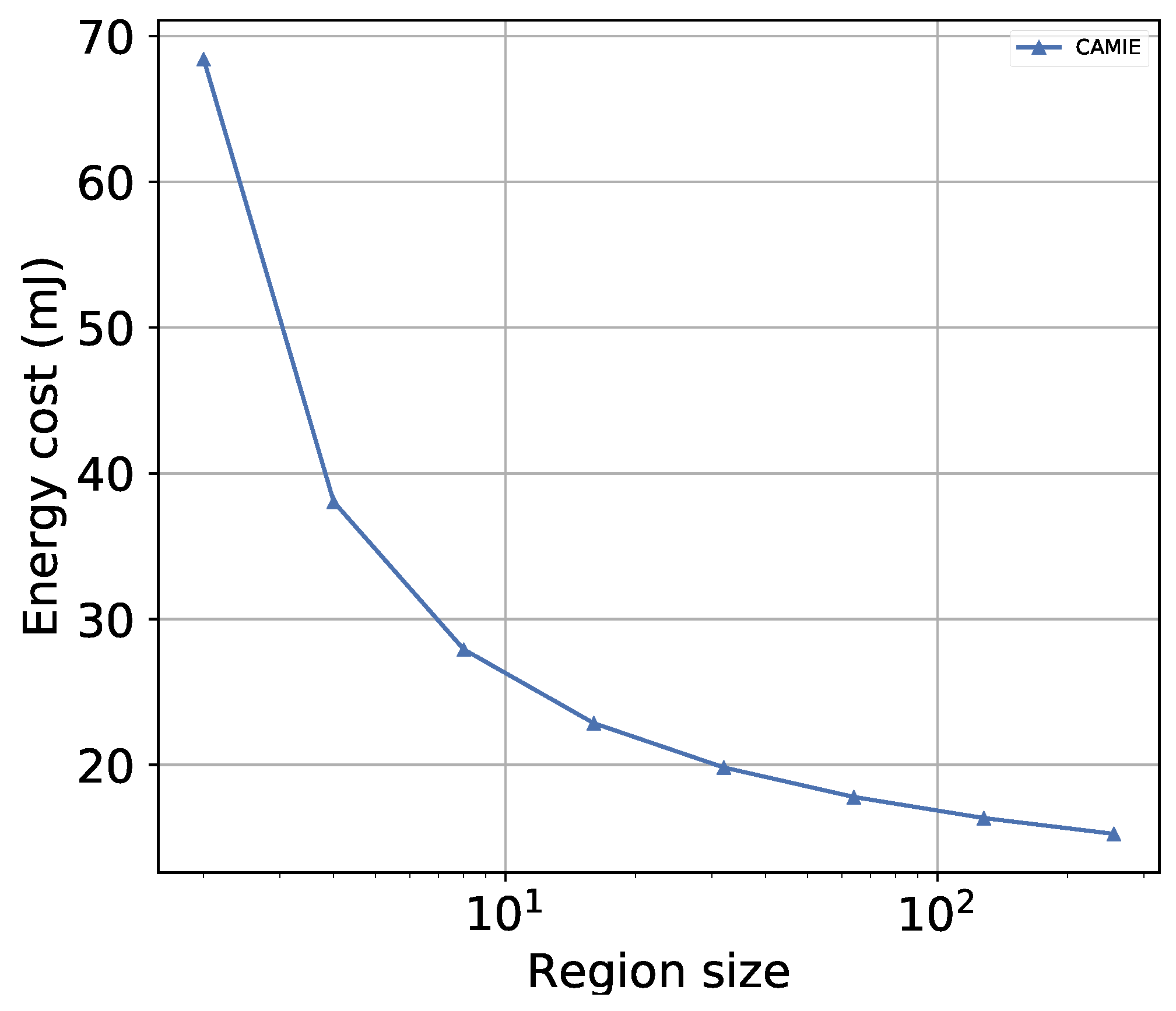
Region size and detection precision. The probabilistic detection precision of
CAMIE is also related to the size of region. Additionally,
CAMIE supports target search by adding
in the request to localize maintenance targets. For both attestation and target search, smaller regions are helpful for reducing the number of devices to manually inspect. However, when the region size is smaller, the swarm network has more regions and the overhead also increases.
Figure 7 shows the change of the energy cost for different region sizes. If the number of regions increases, then more region summaries are accumulated for communication. In
Figure 7, the region size is changed from 2 to 256. We can see the clear trade-off relation between region size and energy cost; the average energy cost required for a device decreases rapidly as the region size increases.
6.4. Simulation
In order to evaluate runtime in more realistic settings, we performed simulation on
CAMIE compared to SEDA and SANA with a custom Python event simulator. In the simulation, we use the similar setting of [
21]; we assume that the swarm network uses ZigBee wireless communication links (250 Kbps) and each device is implemented in the TyTAN architecture (to set the runtime parameters). In the simulation, devices are randomly placed within the 200 m × 200 m square area. The communication range of a device is 20 m. We compare the runtime of
CAMIE to SEDA and SANA by varying the number of deployed devices.
Figure 8 shows the runtime of
CAMIE, SEDA and SANA. All the schemes in
Figure 8 have performed the attestation process with the 4-ary attestation tree. Due to the OAS aggregation process for the exact detection precision, SANA has the largest runtime.
CAMIE can achieve less runtime than SANA but is still higher than SEDA. When the number of nodes is 3000,
CAMIE has 25.72% higher runtime than SEDA but SANA has 133.5% higher runtime than
CAMIE.
7. Conclusions
The swarm attestation targets large-scale IoT/WSN networks and validates the sanity of the network. We presented CAMIE, a lightweight attestation method. The previous methods perform efficient attestation on a large-scale swarm network. However, they do not handle scalable identification of compromised devices. CAMIE provides a region-based identification of target devices. For this purpose, we proposed the binary-embedded tag generation and the regional aggregation of measurement results. The evaluation shows that the proposed scheme can provide identification and localization of compromised devices (probabilistic detection precision) with the reduced energy cost by one third. In particular, due to the region summary aggregation, CAMIE can provide informative attestation reports even in a large-scale malware infection, which causes significant communication overhead to identification mechanisms of previous schemes.
CAMIE can facilitate the management process, but it still has challenges. We assume that the network topology is static during the attestation process. However, it may not be in the same situation for high-mobility environments. To support high-mobility swarm networks, we have to handle frequent changes of region members efficiently. Like most collective attestation approaches, CAMIE relies on static registration of devices to neighbors to localize the detection process. Thus, considering topology changes, we are improving the membership management in both the operation and attestation phases as our future work. As the merged component ID is composed into a device tag, a region can be described by aggregated tags of member devices for dynamic membership.


