Review

Wireless Power Transfer via Subterahertz-Wave

Department of Engineering Mechanics and Energy, University of Tsukuba, Tsukuba 305-8577, Japan
*
Author to whom correspondence should be addressed.
Appl. Sci. 2018, 8(12), 2653; https://doi.org/10.3390/app8122653
Submission received: 25 September 2018 / Revised: 1 December 2018 / Accepted: 13 December 2018 / Published: 17 December 2018
(This article belongs to the Section Energy Science and Technology)

Abstract

:
Research on wireless power transmission by a rectenna using millimeter waves and subterahertz waves is gaining attention. It is expected that energy harvesters at high frequencies will be developed for use with future 5 G. High-power wireless power supply to various applications will be possible because of miniaturization of the rectenna. As described herein, we investigate earlier studies of millimeter-wave wireless power supply, selecting and explaining salient examples of millimeter-wave high power wireless power supply.

1. Introduction

Wireless power supply is gaining attention as a new power supply source. Especially, with the miniaturization of applications, great demand has arisen for technological development to supply sufficient power to limited areas wirelessly. Wireless power transmission methods of several types exist. This paper specifically emphasizes a wireless power feeding system that can extract electromagnetic wave from outside the device as it is with DC power using a rectifier and antenna apparatus (rectenna). Long distance power feeding is possible as a point of merit of wireless power supplies using a rectenna. It has become more easily adaptable to diverse applications. Application examples include space solar power systems, power supply to UAVs such as drones, internet of things (IoT) wireless sensors, RFID (Radio Frequency Identification), etc. Using millimeter waves, sub-terahertz waves, terahertz waves, i.e., using higher frequencies for wireless power supply, one can miniaturize a rectenna and increase the DC output power per unit of rectenna area (hereinafter, rectenna power density). Results show that the larger the rectenna power density becomes, the greater the amount of DC power that can be sent to a limited area. Furthermore, by increasing the frequency, the beam directivity can be improved: The beam diffusion is suppressed. In addition, the beam spot diameter becomes small even at a long distance. However, it is suitable for long-distance wireless power supply purposes because it can reduce the power loss that the beam dissipates to the outside. It was evaluated quantitatively as the beam efficiency [1].
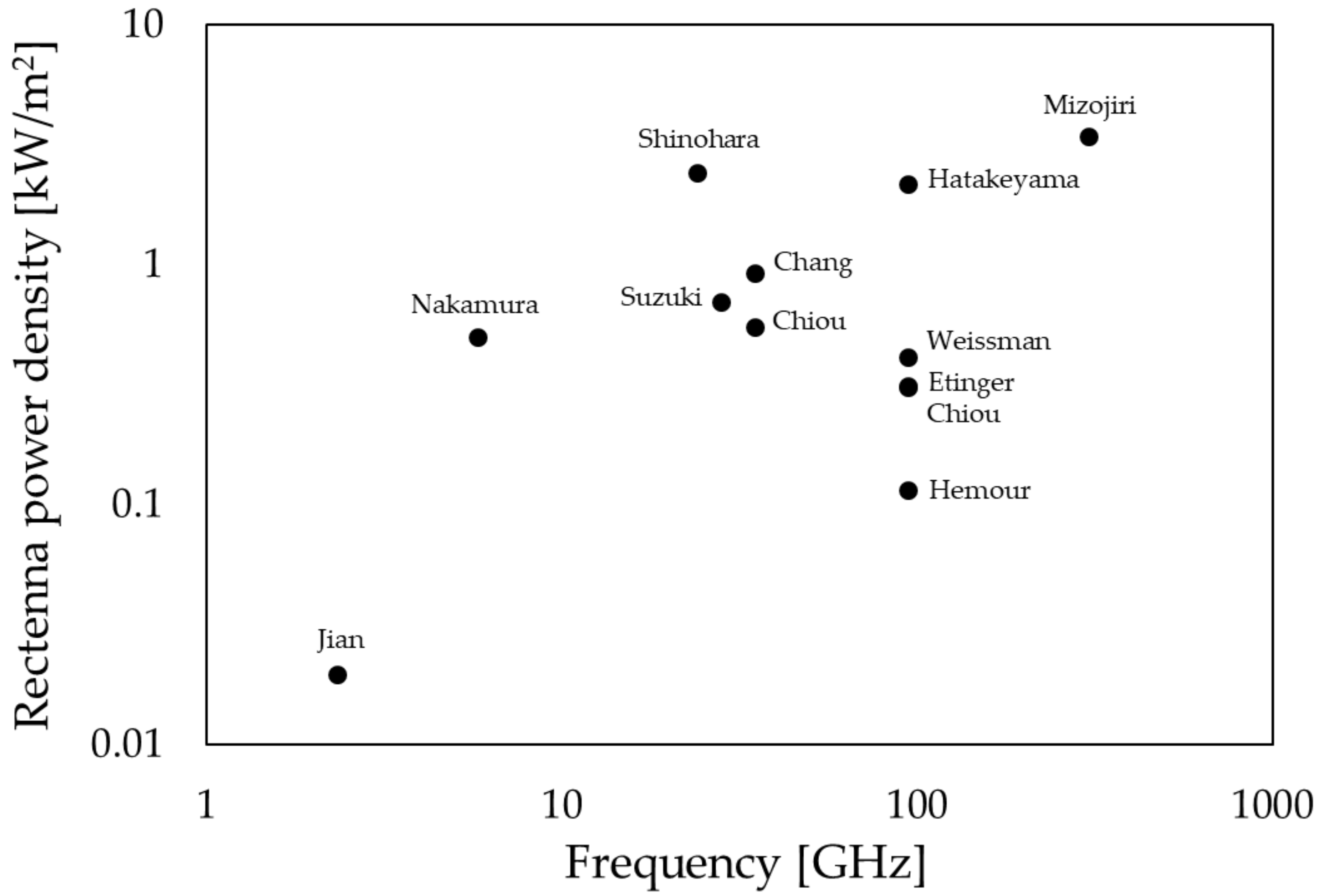
Rectenna RF–DC conversion efficiency for the frequency in earlier research is presented in Figure 1. The DC output power is presented in Figure 2. The rectenna power density is shown in Figure 3. In addition, the rectenna characteristics described in the research reports listed above are shown in Table 1 and comparison of this work to earlier studies are shown in Table 2 and Table 3. Jian et al. [2] distributed a 16-array antenna to the rectifier circuit at 2.33 GHz, wirelessly powered the drones, and let them fly. Chang et al. [3,4] developed a rectenna that shares frequencies of 2.45–5.8 GHz, which strictly matches the diode impedance analysis, and recorded high rectification efficiency. Additionally, at 10 GHz and 35 GHz, high efficiency was achieved using the same method. Nakamura et al. [5] fabricated a rectifier circuit using GaAs FET at 5.8 GHz. The results show that the rectification efficiency was 80% and that the DC power exceeds 500 mW. Yang et al. [6] fabricated a circularly polarized rectenna with high RF–DC conversion efficiency in the X-band, with a miniaturized rectenna area using a back power feeding structure. Shinohara et al. [7] developed a rectifier equipped with class F load and recorded high RF-DC conversion efficiency of 65.5 % at 24 GHz. Koert et al. [8] Recorded high RF-DC conversion efficiency of 72 % at 35 GHz. In addition, proposed a space power beaming system using a gyrotron. Mavaddat et al. [9] Fabricated a rectenna using a 4 × 4 patch antenna array and LPF at 35 GHz, and carried out near field WPT (Wireless Power Transmission) measurement. Nariman et al. [10] developed a rectenna using a grid antenna at 60 GHz and reported RF–DC conversion efficiency of 32.8% and DC power of 1.22 mW. Furthermore, they proposed a WPT system combining transmission and reception. It is apparent from Figure 1 that the RF–DC conversion efficiency decreases at increasing frequency. Maximum RF–DC conversion efficiency of 80–90% is shown at 2.45 GHz, 5.8 GHz, 10 GHz in the microwave band. In contrast, in the millimeter wave band of 30 GHz to 300 GHz, the RF–DC conversion efficiency was about 50% to as low as 2%. It is apparent from Figure 2 that the microwave band DC output power can be 500–1000 mW, although the millimeter wave band can output only about 10–200 mW. Because the rectenna is smaller even if the power decreases, it is apparent that the rectenna power density of Figure 3 tends to improve along with increased frequency. The greatest cause is circuit loss: diode loss increases as the frequency becomes higher.
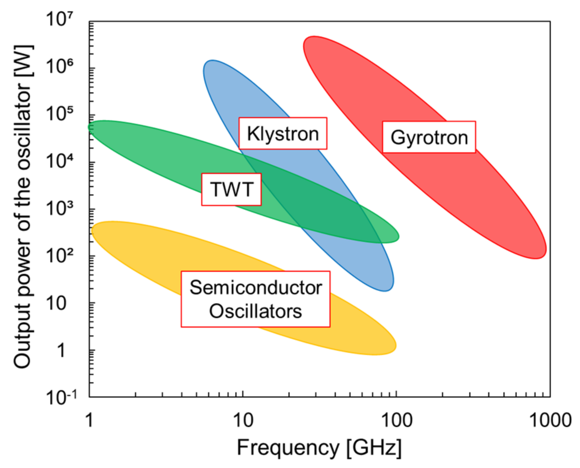
From Table 1, the millimeter wave rectenna mainly used the Schottky barrier diode, which has low junction capacitance and low forward voltage; alternatively, it used CMOS (Complementary metal oxide semiconductor) technology, which is an easily integrated substrate and circuit component. The mainstream of current millimeter-wave rectenna research includes energy-harvesting applications, which achieve high efficiency with low power operation. Such rectenna development is being undertaken for RFID, with wireless sensors for IoT, etc. Pouya et al. proposed a method of implementing an energy-harvesting system applied to IoT from the perspective of rectenna performance, power system, lifetime, and cost [11]. Moreover, Panagiotis et al. have proposed energy-efficient power control in wireless powered communication networks [12]. Research examples of millimeter wave rectennas are the following: rectenna for energy harvester of temperature sensing tag using CMOS 65 nm [13], ultra-small rectenna for microrobot [14], high-efficiency dual-frequency rectenna using CMOS 0.13 µm [15], rectenna as first fully on-chip energy harvester using CMOS 65 nm [16], RF–DC conversion efficiency improvement achieved using high-precision fabrication of MMIC (Monolithic Microwave Integrated Circuit) and MEMS (Micro Electro Mechanical Systems) [17,18]. Furthermore, as another major factor with which the high-power wireless power supply experiment in the millimeter wave band is not actively conducted, the maximum output power of the oscillation source greatly decreases as the frequency increases [19]. As might be apparent from Figure 4, there is a large power oscillation source that is readily available in the microwave band. However, in the millimeter wave band, only TWT (Traveling Wave Tube), a klystron, and a gyrotron can output power beyond kilowatt order. Furthermore, for frequencies higher than 100 GHz, only a gyrotron has a sufficiently high power oscillation source. Gyrotrons are gaining attention as a source of future high-power wireless power supply for space solar power systems and stratospheric aircraft [20]. Output power and output frequency have improved each year [21]. Nevertheless, few earlier studies have used a gyrotron for wireless power supply: Ariel University in Israel has conducted wireless power supply experiments using a gyrotron with 5 kW output at 94 GHz [22]. The University of Tsukuba in Japan has 25 array rectennas using a 28 GHz gyrotron [23], achieving a submillimeter-wave wireless power supply using a 303 GHz gyrotron [24]. It is therefore considered that experiment of high-power wireless power supplies using gyrotrons will have great influence.
To summarize, it is possible to carry out long-distance and high-power wireless power supply with high directivity, which raises the rectenna power density using millimeter waves. However, the RF–DC conversion efficiency and DC output power decrease because circuit and diode losses increase. It is necessary to conduct a wireless power supply using a high-powered oscillation source such as a gyrotron. We focused on the superiority of the sub-terahertz and conducted high power wireless power transmission at 28 GHz, 94 GHz and 303 GHz [18,23,24]. Those works are the cutting edge of high power and high-frequency wireless power transmission. We succeeded in improving RF-DC conversion efficiency and rectenna power density of sub terahertz rectenna and demonstrated feasibility of wireless power transmission using gyrotron. These results conclude that sub-terahertz is suitable for long distance high power wireless power transmission.

2. Wireless Power Beaming

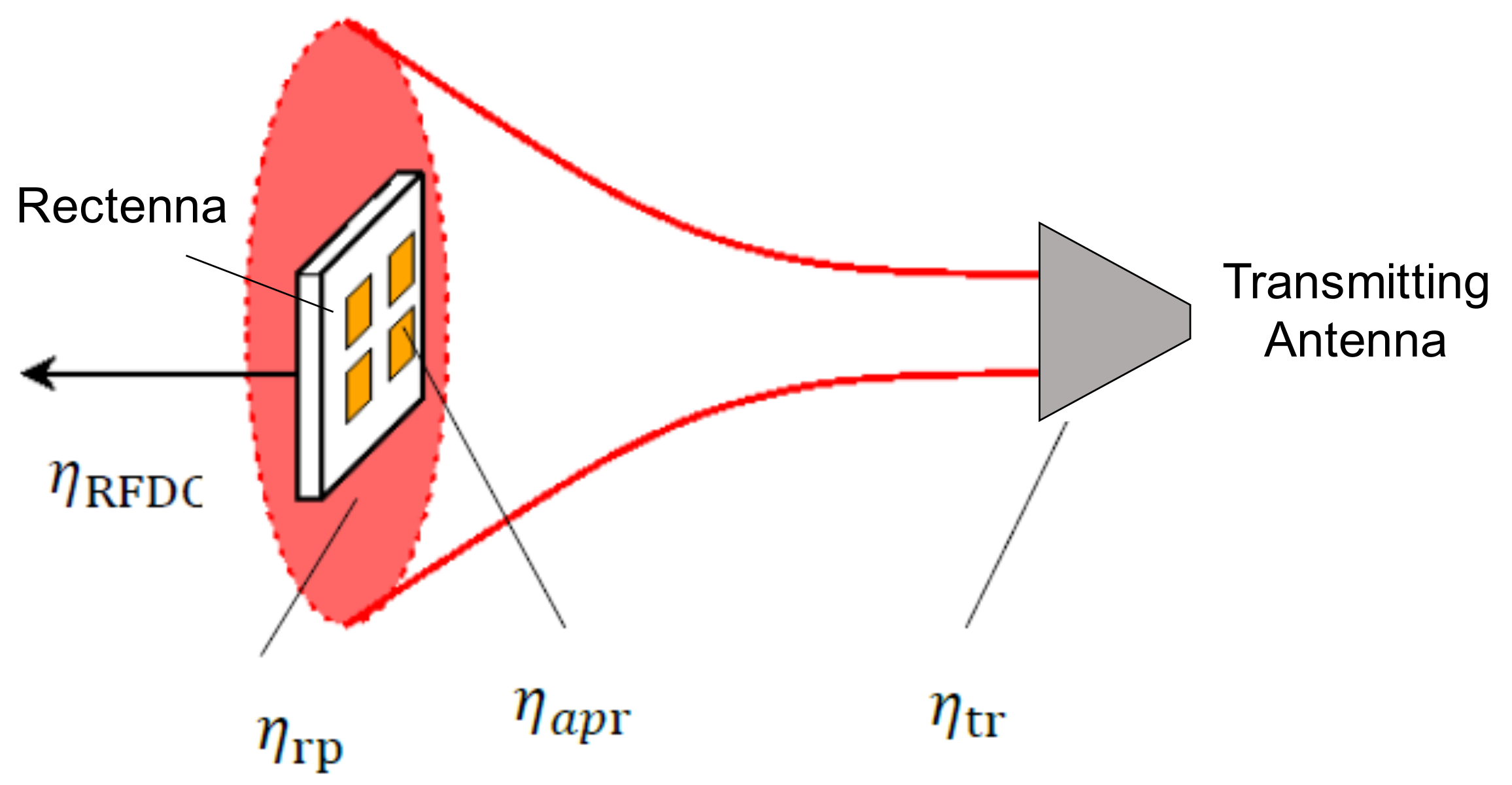
A rectenna is completed by integrating a fabricated antenna and the rectifier. The power transmission efficiency η of the entire wireless power supply is obtainable as η = Pout/P0 from the output power of the oscillation source by P0 and the DC output power Pout obtained using the rectenna. Furthermore, the power transmission efficiency η can be estimated theoretically using the following parameters: antenna gain Gr, wavelength λ, the area actually occupied by the antenna on the circuit pattern Aact, the antenna’s effective area Aeff, the aperture area of transmitting antenna At, the aperture area of receiving antenna Ar, transmitting distance d, beam radius ω, beam waist ω0 of the power transmission antenna, and power density S at the rectenna installation point, which is obtainable from the beam profile using an IR camera. The conceptual diagram of power transmission efficiency is shown in Figure 5. The transmission efficiency of the entire wireless power supply by the rectenna can be estimated theoretically using Equations (1)–(5).
Total transmission efficiency
η =   η t r η a p r η r p η R F D C
Transmission antenna efficiency (normally 1, when a reflection exists, decrease by that amount)
η t r = 1
Antenna aperture efficiency
η a p r = A e f f A a c t = ( λ 2 4 π ) G r A a c t
Beam efficiency
η r p = 1 exp ( A t A r λ 2 d 2 )
RF-DC conversion efficiency
η R F D C = P D C P i n = P D C S × A e f f = P D C S × ( λ 2 4 π ) G r
From the equations presented above, one can estimate the amount of specified amount of wireless power supply to the object at a distance d away using the antenna gain, RF–DC conversion efficiency, output power of the power generation source, and beam profile.
From Equations (4), it is apparent that if the aperture area of the transmitting and receiving antenna is always constant, raising the frequency is sufficient to increase the beam efficiency. These factors clarify the merit of using millimeter waves for wireless power supply.
Particularly, the diode performance determines the rectenna’s maximum RF–DC conversion efficiency and the DC output power. The value RC (The RC time constant) multiplied by the series resistance R and the junction capacitance C expresses the time constant of switching. The smaller this value becomes, the more the cutoff frequency and the RF–DC conversion efficiency can be increased at high frequencies. Equation (6), which expresses the diode efficiency ηd and relational expression (7) of the RC time constant and the breakdown voltage VMAX using the following parameters: The angular frequency ω, Dielectric breakdown electric field Ec, Electron mobility μ.
η d = 1 1 + 1 4 ω 2 ( R C ) 2
R C = 2 V M A X μ E c
From Equation (6), one can infer the possibility of improving the RF-DC conversion efficiency as the RC time constant decreases. However, simultaneously, the breakdown voltage decreases because of the relation shown in Equation (7).
When a wireless power transmission unit with the rectenna is mounted on a small aircraft such as a drone, a wireless sensor to the IoT, a mobile device, etc., some concerns arise that the power transmission efficiency will be remarkably lowered because many factors such as the radiation pattern, axial ratio, input power, optimum load, and the like deviate from optimal values. Therefore, it is indispensable to develop a rectenna combining a redundant antenna such as a broadband circularly polarized antenna and a rectifier circuit.

3. Research Report on Millimeter-Wave High-Power Wireless Power Transmission

3.1. 28 GHz Rectenna

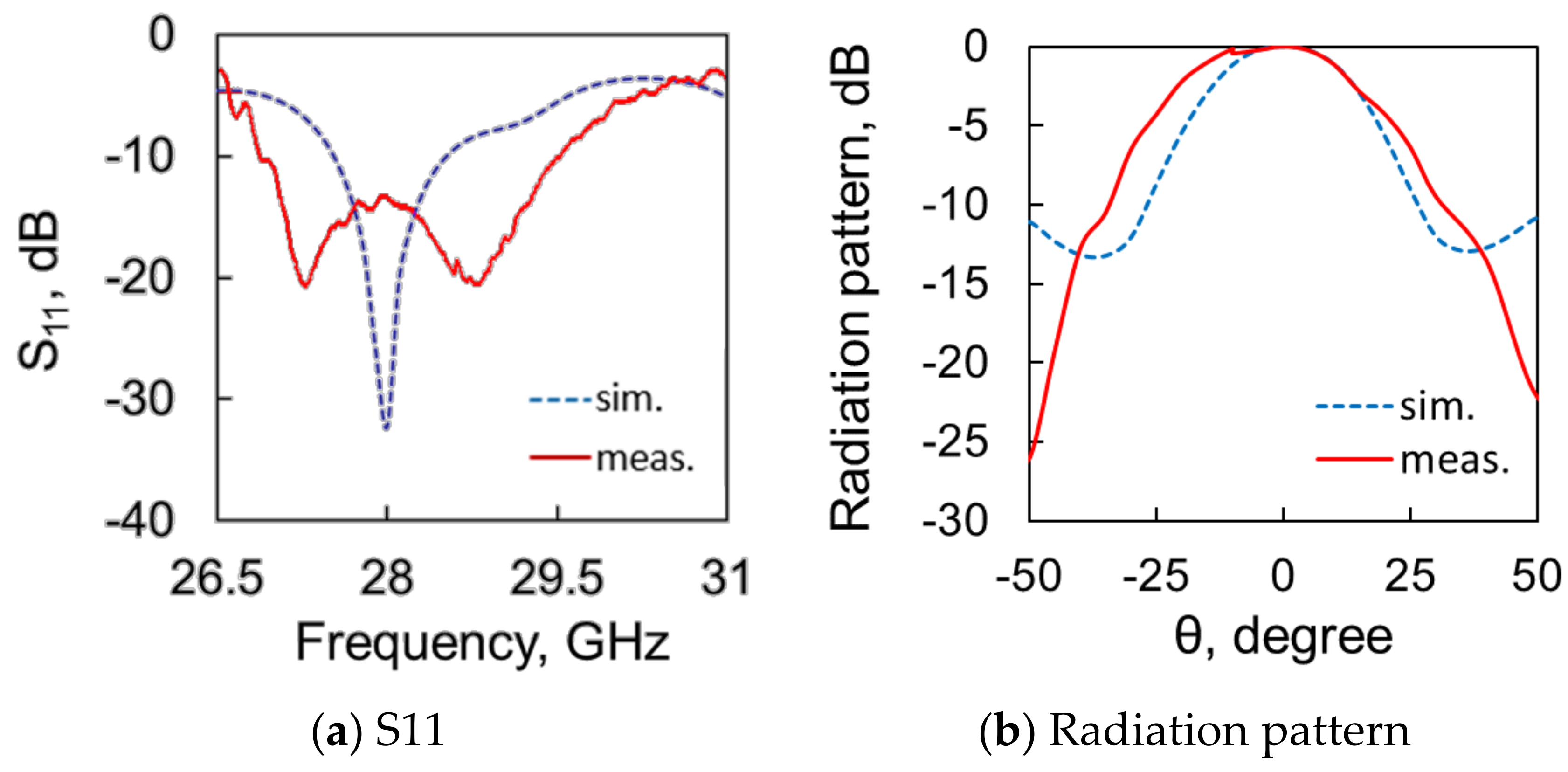
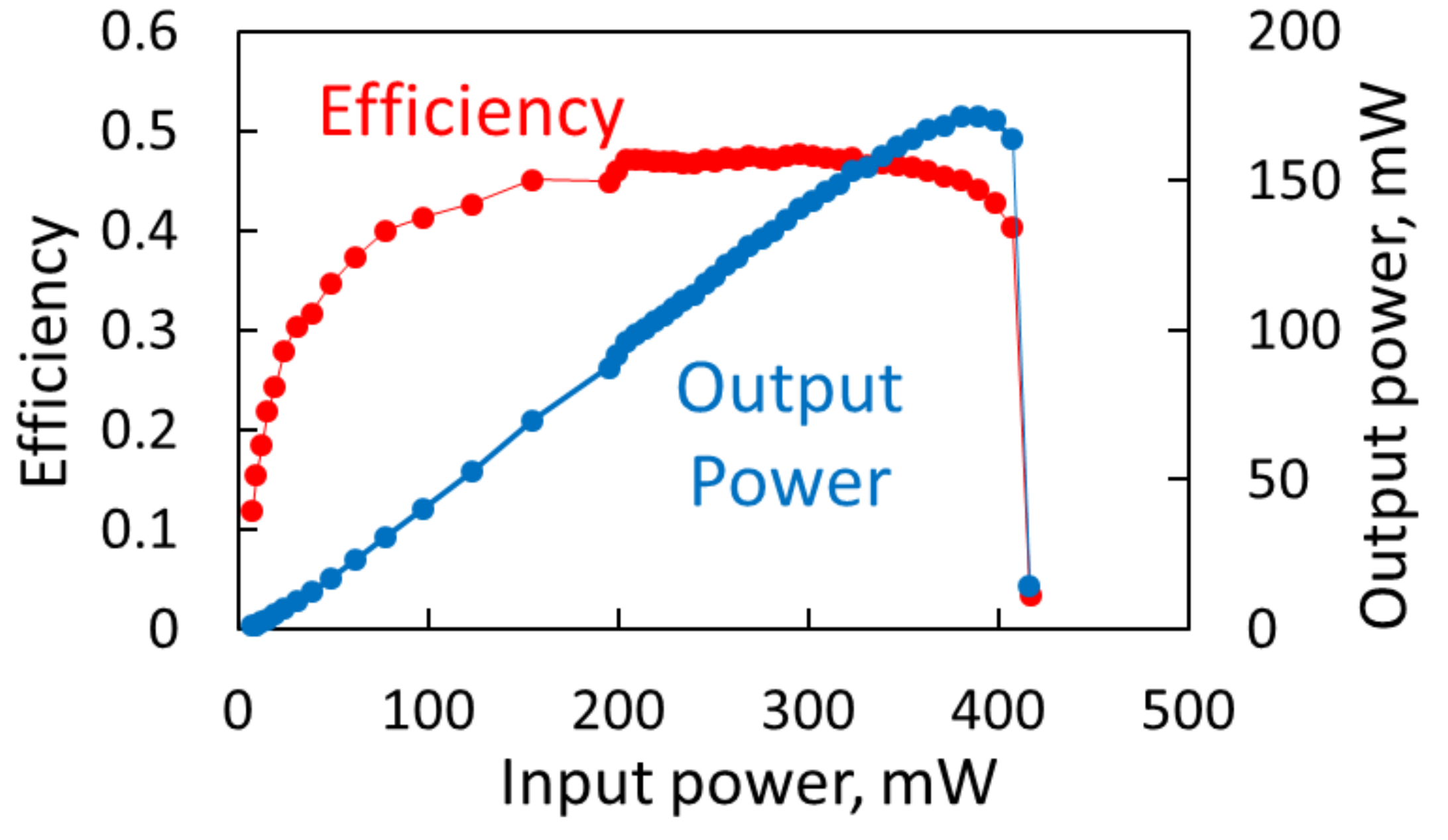
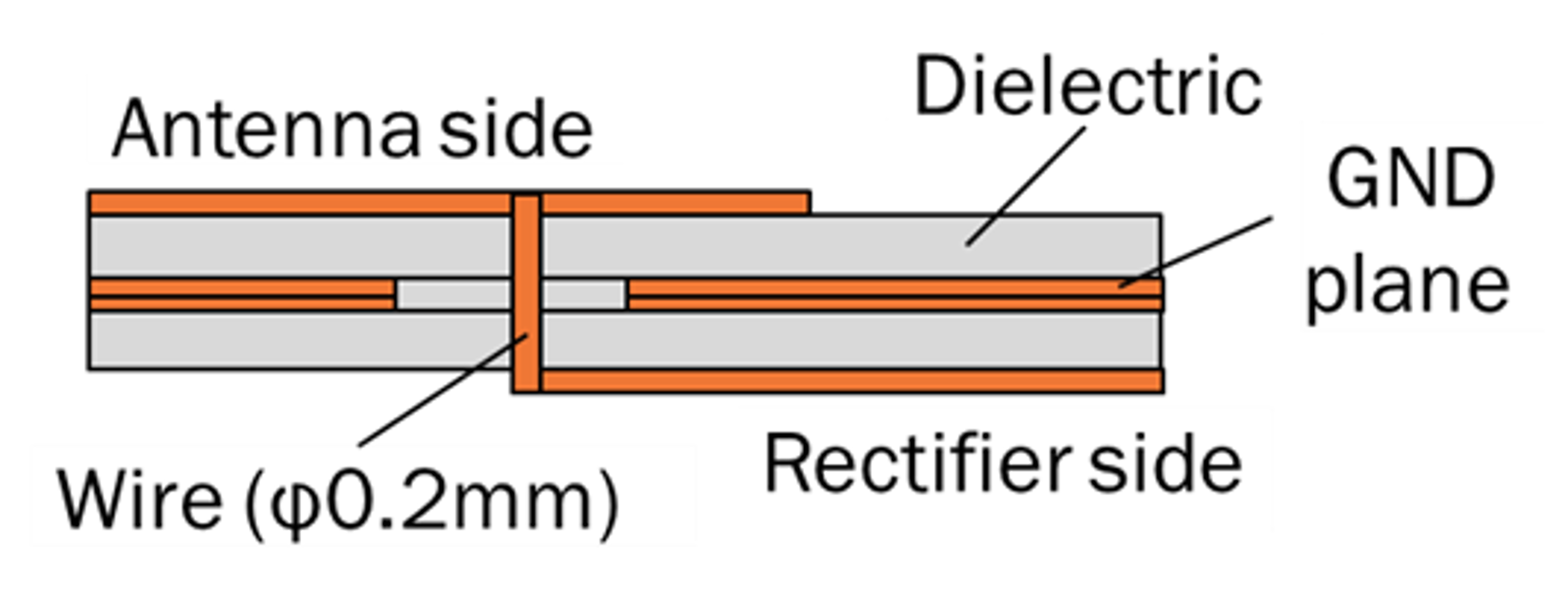
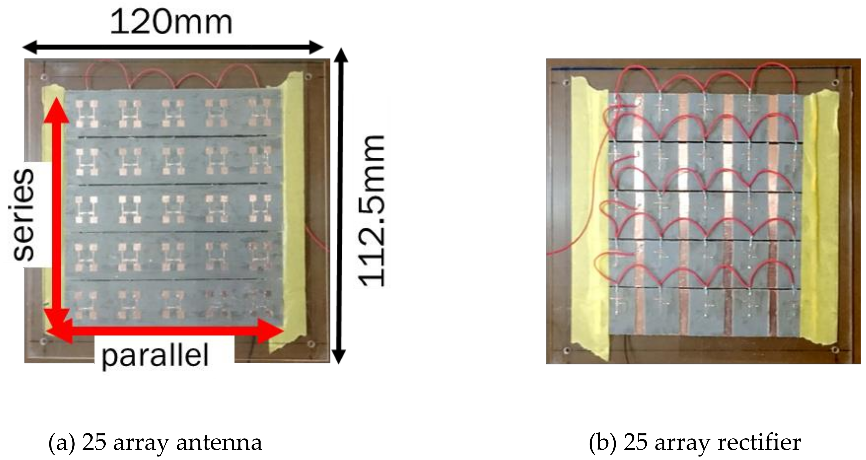
A circuit pattern was fabricated using a substrate processing machine (Diclad880; Rogers Corp, Chandler, AZ, USA) and using MSL as a transmission line. The diode used a GaAs Schottky barrier diode (MA4E1317: Macom, Lowell, MA, USA). The structure of a 28 GHz antenna and a rectifier is portrayed in Figure 6. The Electromagnetic field simulators of EMPro and ADS (Keysight Technologies Co. Ltd., Santa Rosa, CA, USA) were used for designing the antenna and rectifier. Measurement results of the antenna reflection coefficient and radiation pattern are shown in Figure 7. We obtained antenna reflection coefficient -12.9 dB and gain of 9.0 dBi to achieve high gain using a four-element array. The rectifier is made of a single shunt in which diodes are inserted in parallel. It is equipped with a class F load which is a stub structure to reapply the fundamental wave and harmonic to the diode for enhancing RF-DC conversion efficiency [7]. Measurement results of the rectifier are shown in Figure 8. The maximum RF–DC conversion efficiency is 47.7% (295 mW input, 130 Ω load resistance). The maximum DC output power is 171.4 mW (389 mW input, 130 Ω load resistance). Also, the maximum rectenna power density was 0.86 kW/m2. To obtain higher rectenna power density, the rectenna was arrayed 25 rectenna. the rectenna area was reduced to the greatest extent possible by assembling the antenna and the rectifier circuit with a back feeding structure. The back feed structure is shown in Figure 9. 25 array antenna was connected in 5 parallel and 5 series, shown in Figure 10. DC output power was integrated into one load resistance of 130 Ω.
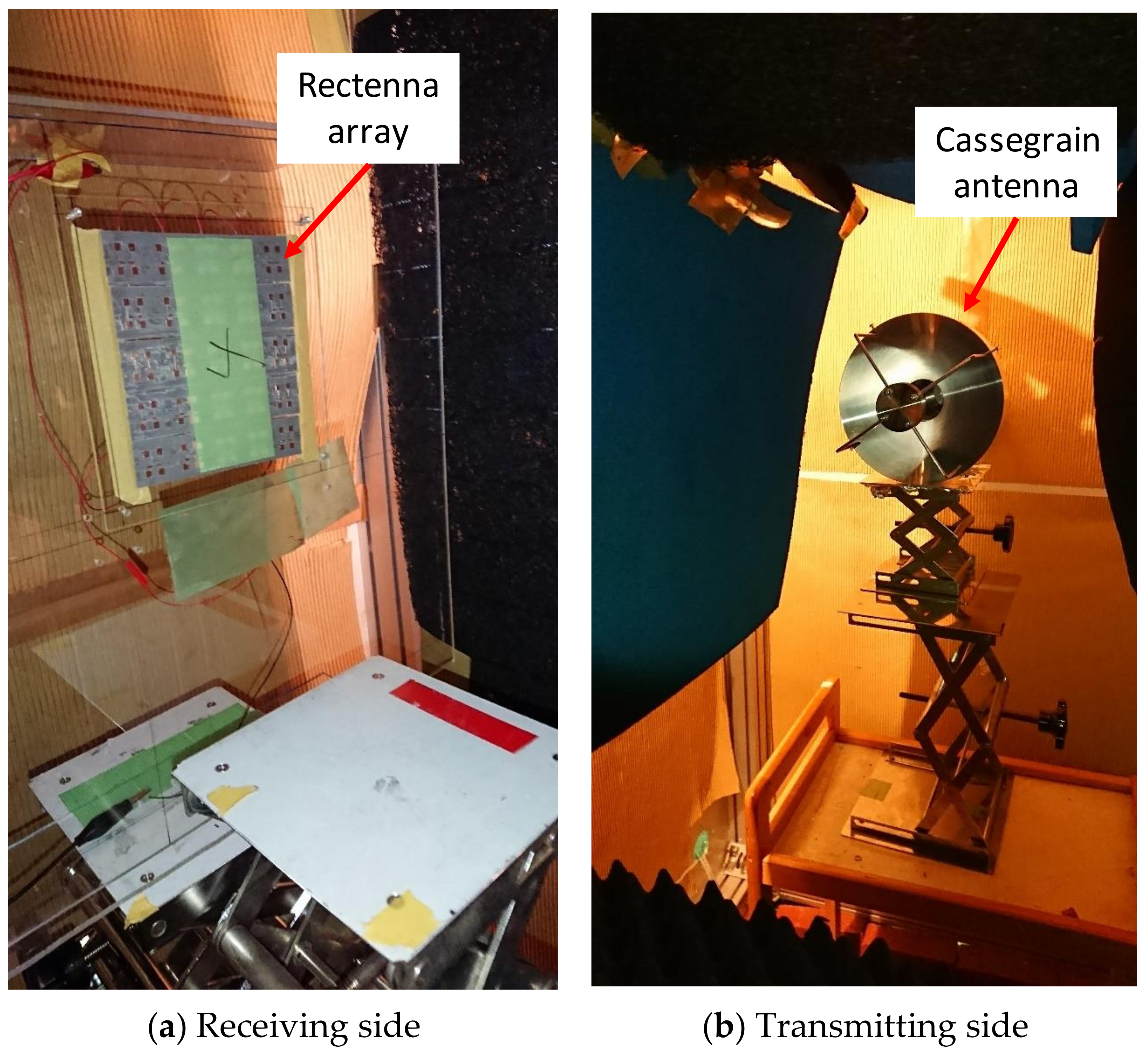
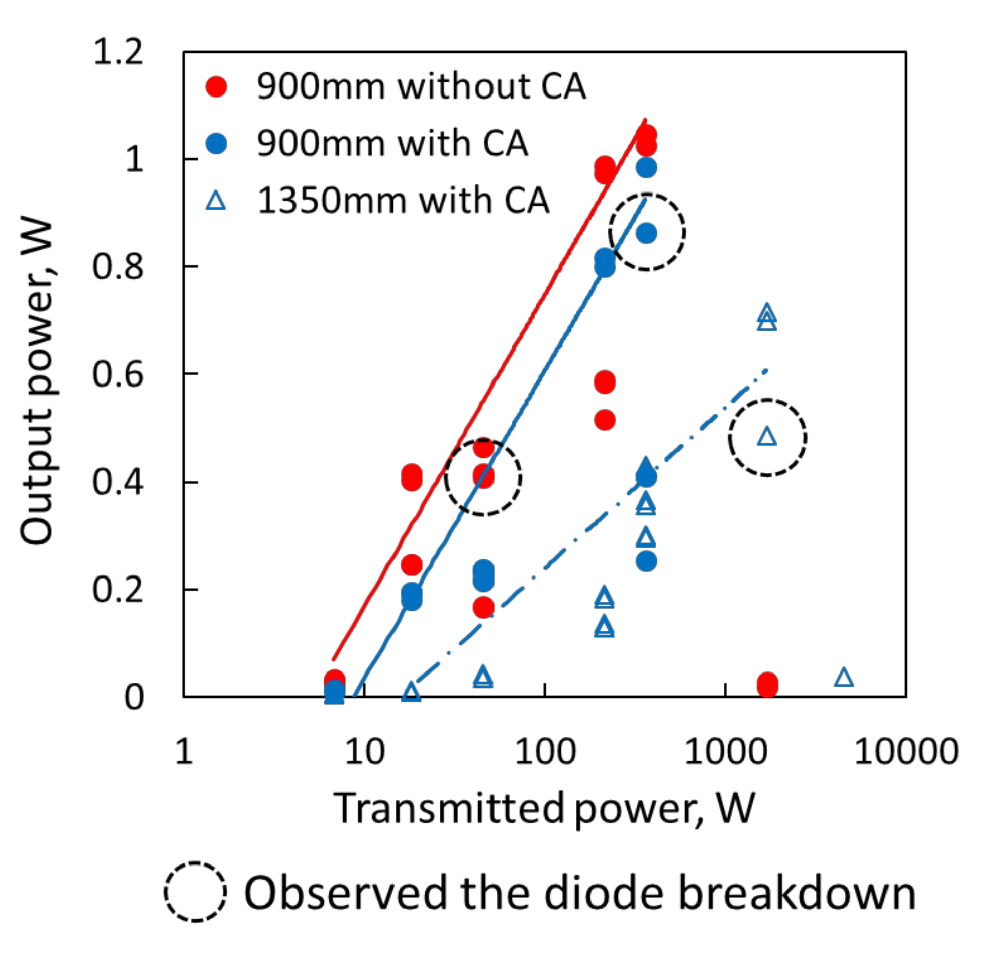
The 28 GHz gyrotron used as the wireless power supply is at the Plasma Research Center of the University of Tsukuba [25]. The measurement setup is portrayed in Figure 11. The gyrotron output power was fixed at 52.9 kW. Measurements were taken at two points of 0.9 m and 1.35 m. The input power to the rectenna was altered by changing the attenuation materials. Actually, WPT using the Cassegrain antenna (CA) was also applied to increase the transmission beam directivity. The measurement result of WPT using 28 GHz gyrotron is presented in Figure 12 and Table 4. Without the Cassegrain antenna, it means that the beam is emitted directly from the corrugated waveguide which is the window of the gyrotron. The maximum DC output power and the maximum total transmission efficiency were 1.05 W and 2.30% at a distance of 900 mm. The maximum transmission efficiency of 2.30% was recorded at a DC output of 0.40 W when the attenuation was 34.7 dB. The maximum DC output of 1.05 W was recorded when the attenuation was 24.7 dB, and then the transmission efficiency was 0.29%. The transmission efficiency dropped so sharply when the distance is increased from 900 mm to 1350 mm. It is because the condensing position of the Cassegrain antenna was 900 mm, therefore at 1350 mm, greatly shifted the converging position. To calculate the total transmission efficiency, considering each efficiency of Equations (1)–(5), we estimated the theoretical total transmission efficiency of 2.35% using the power ratio received by the rectenna caused by the spread of the Gaussian beam, the aperture efficiency of the antenna, and the RF–DC conversion efficiency of the rectifier. This value roughly agreed with the experimentally obtained value.

3.2. 94 GHz Rectenna

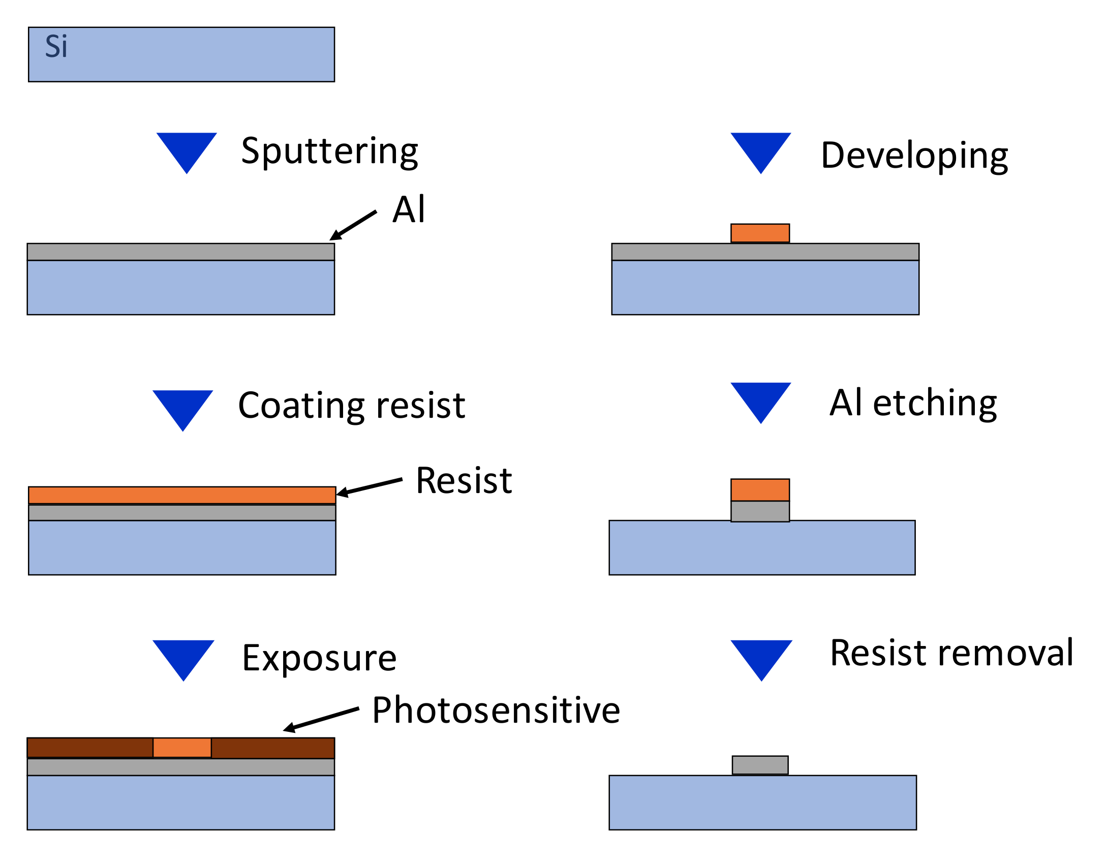
A 94 GHz rectenna was fabricated using semiconductor microfabrication technology. Small manufacturing errors strongly affect the RF–DC conversion efficiency because the wavelength is extremely short: about 3 mm at 94 GHz. The fabrication process used for this method is roughly divisible into two procedures. The first is sputtering of aluminum as a conductor on a Si substrate. Then one must draw a specified circuit pattern using photolithography, followed by etching to leave only the circuit pattern. This process is shown in Figure 13.
(1)
Aluminum is sputtered or vapor-deposited on the Si wafer (considering the skin depth).
(2)
Apply a photosensitive resist on it.
(3)
Draw the circuit pattern using the electron beam drawing apparatus.
(4)
Develop with TMAH (Tetramethylammonium hydroxide)
(5)
The resist is peeled off. The mixed acid aluminum etching solution etches the exposed Al.
(6)
Only the Al circuit pattern remains.
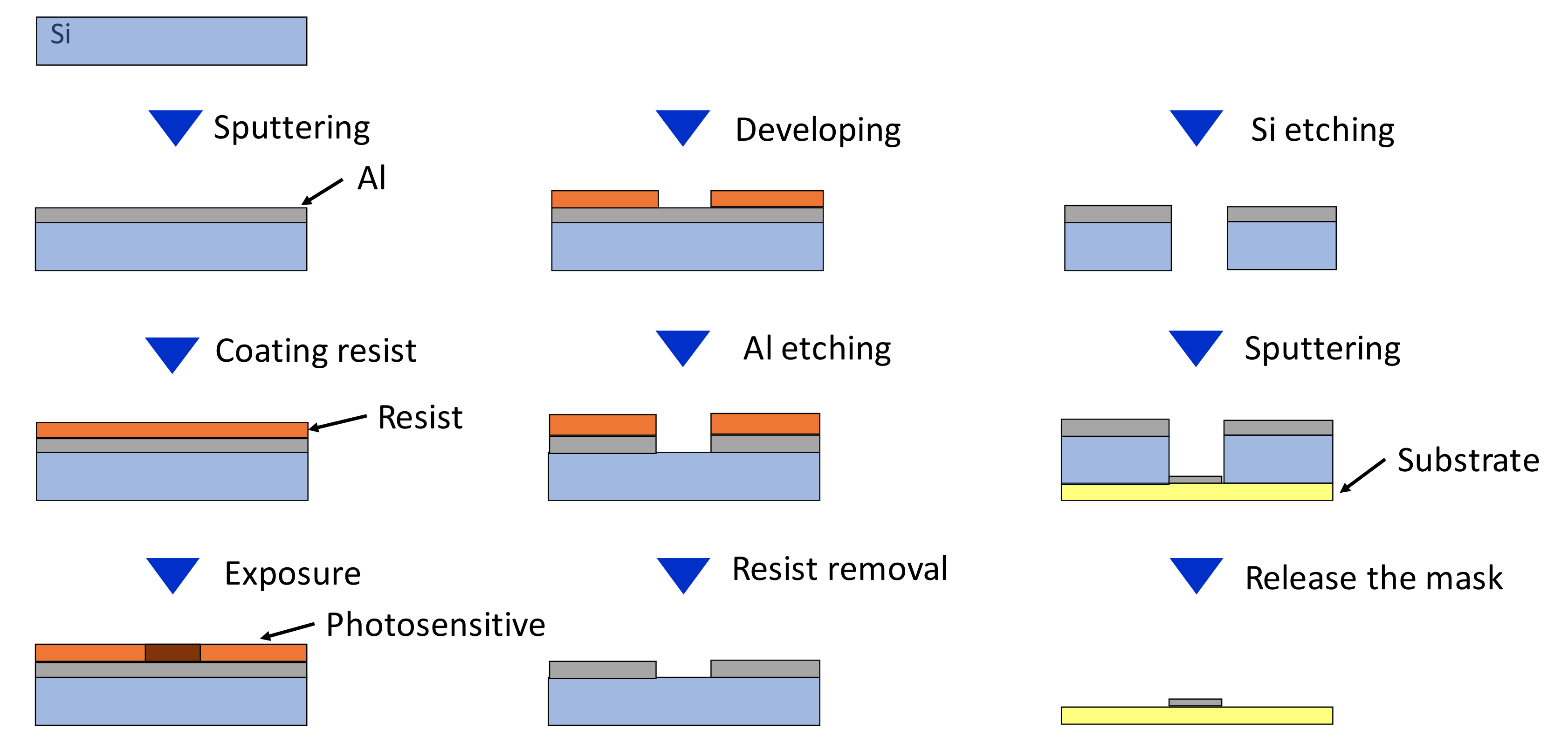
The second procedure is circuit pattern mask preparation by removing a circuit pattern itself by etching together with a Si substrate. Using this mask, cover another substrate and sputter again. This method is shown in Figure 14.
(1)
Aluminum is sputtered or vapor-deposited on the Si wafer (considering the skin depth).
(2)
Apply a photosensitive resist on it.
(3)
Draw the circuit pattern using the electron beam drawing apparatus.
(4)
Develop with TMAH.
(5)
The resist is peeled off. Then the mixed acid aluminum etching solution etches the exposed Al. Only the circuit pattern is exposed Si.
(6)
Silicon is etched by deep silicon device to complete silicon mask.
(7)
Cover the dielectric substrate with a silicon mask and Al sputtering or vapor-evaporation.
Using the former procedure, highly accurate patterns are producible directly. Consequently, fabrication with higher precision is possible. However, it is possible to use only Si or a substrate capable of semiconductor process as the substrate. A benefit of the latter is that sputtering and vapor-evaporation can be performed on low-loss dielectric substrates other than Si.
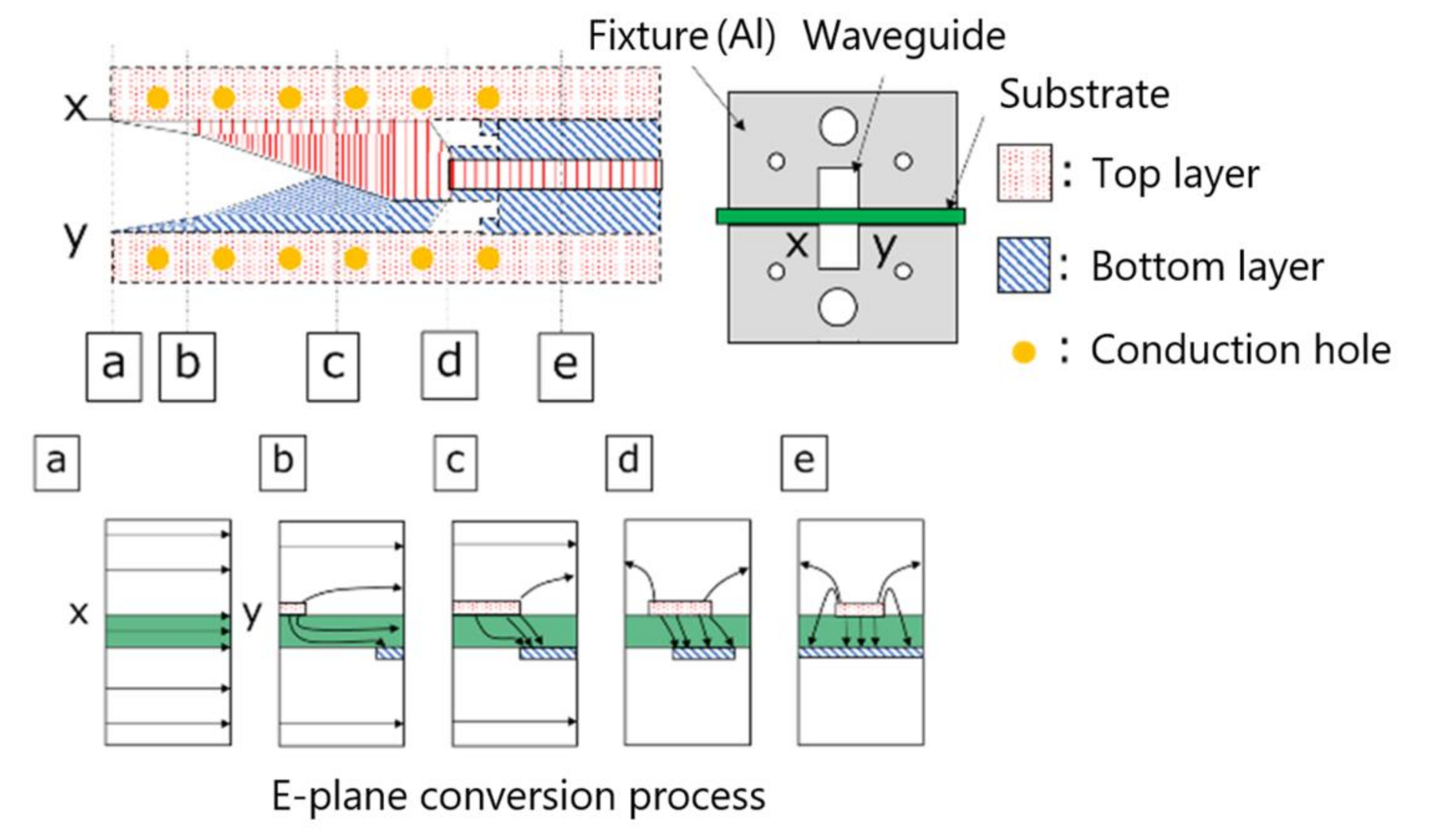
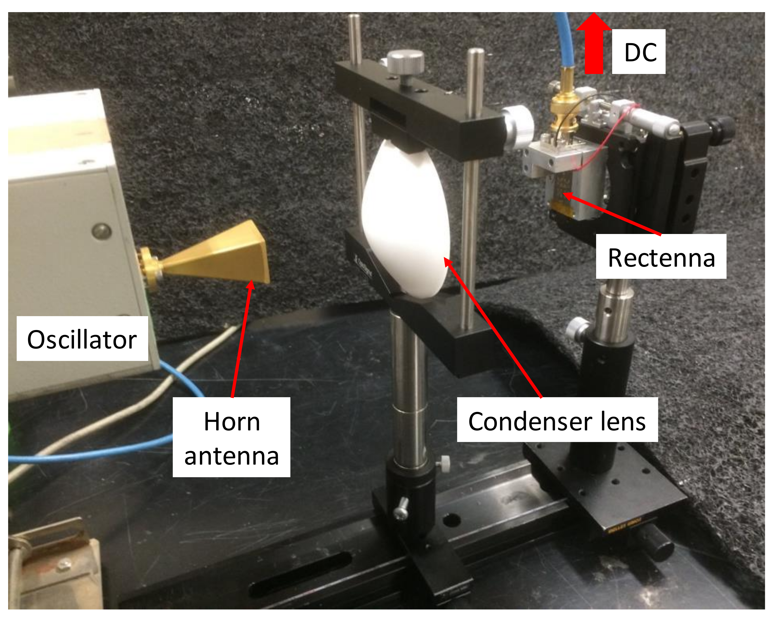
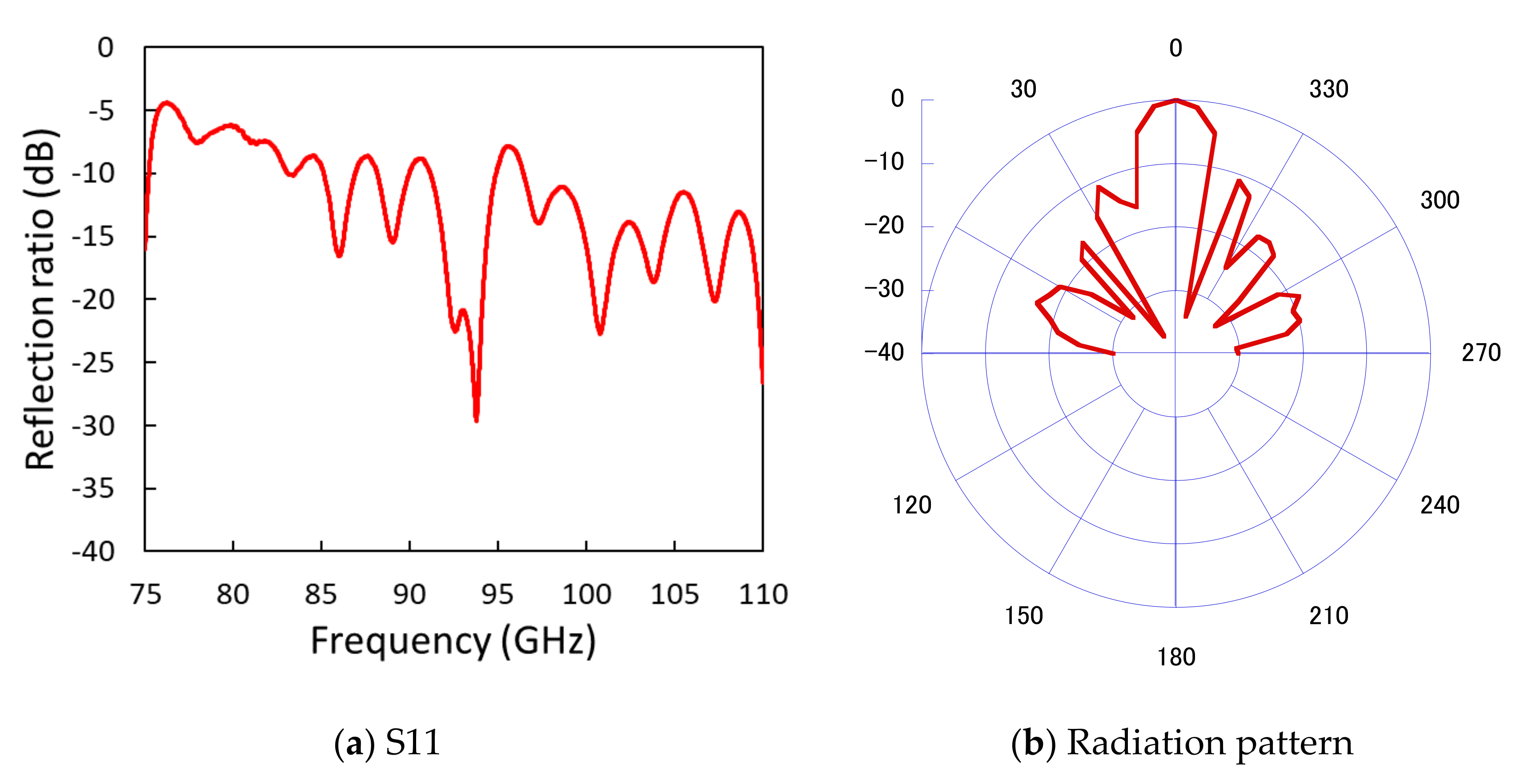
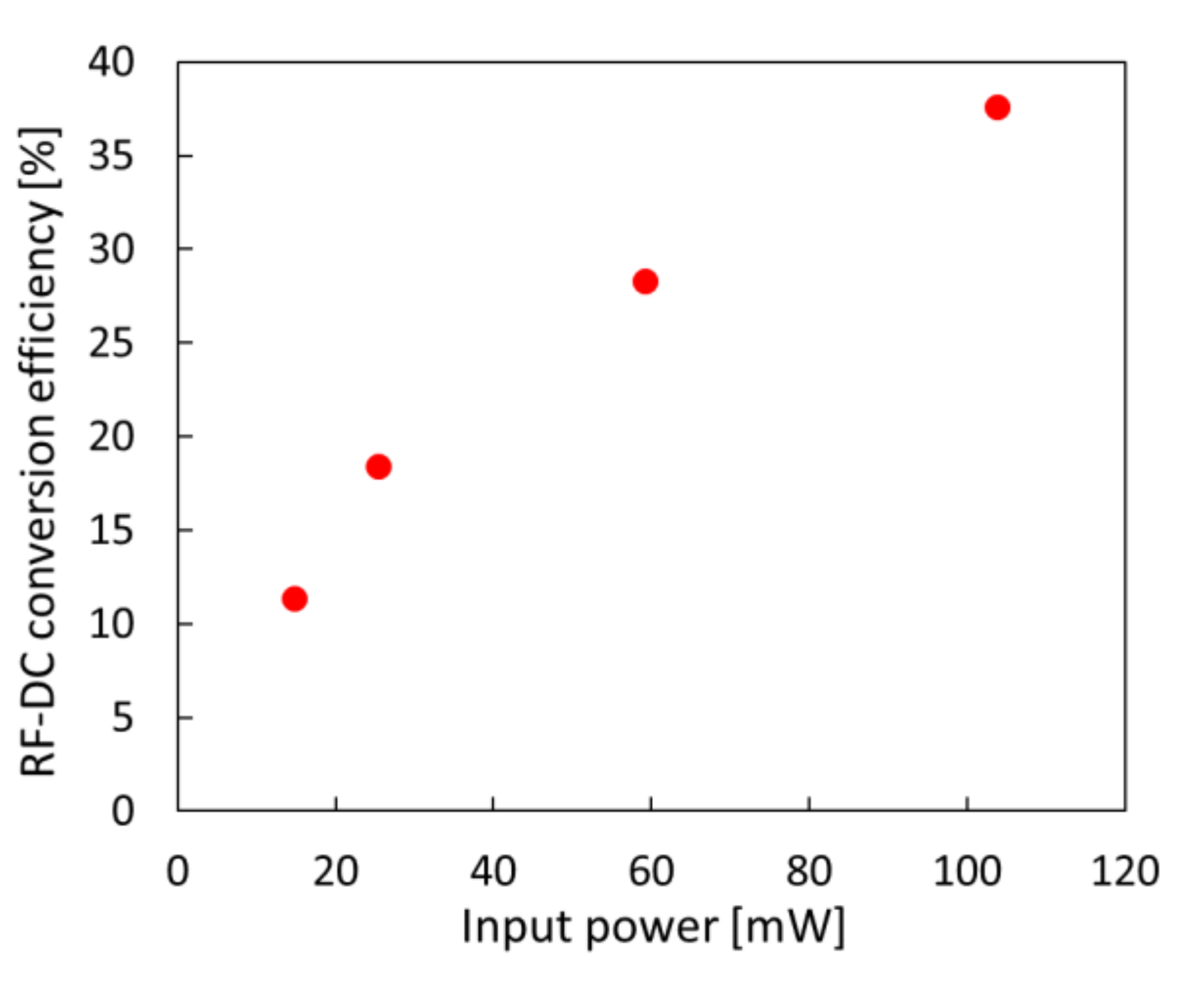
The structure of the 94 GHz antenna and rectenna is shown in Figure 15. The Electromagnetic field simulators of EMPro and ADS (Keysight Technologies Co. Ltd., Santa Rosa, CA, USA) were used for designing the antenna and rectifier circuit. The antenna and the rectifier were designed with matching impedance respectively and integrated as a rectenna. A 94 GHz rectifier was fabricated by Al vapor-deposition on a PTFE (polytetrafluoroethylene) substrate using a Si mask. The PTFE substrate (NPC-F220A, Nippon Pillar Packing Co. Ltd., Osaka, Japan) has a low dielectric constant of 2.17. The diode (MA4E1310, Macom, Lowell, MA, USA) has high breakdown voltage and low junction capacitance. Therefore this diode can exhibit high RF–DC conversion efficiency with high power. For the connection between the diode and circuit, Ag conducting paste is used. The flip chip bonder was used to bond the diode while pressing the diode against the circuit. The rectifier was fabricated in a single series. On the input side, the notch filter is inserted to reapply the second harmonic to the diode. On the output side, the notch filter is inserted to reapply the fundamental wave to the diode. The finline structure is shown in Figure 16. Measurement of the rectifier is done using finline to convert the transmission mode of the MSL-to-waveguide by sandwiching the finline in the Al fixture [26]. The measurement setup is shown in Figure 17. Results are shown in Figure 18 and Figure 19. The DC voltage was measured by connecting the oscilloscope and by calculating DC output power and RF–DC conversion efficiency from the load resistance value and input power. To increase the power received by the antenna, the beam is focused by a condensing lens. Results show that the maximum RF–DC conversion efficiency was 38%. The DC output power was 39 mW.

3.3. 303 GHz Rectenna

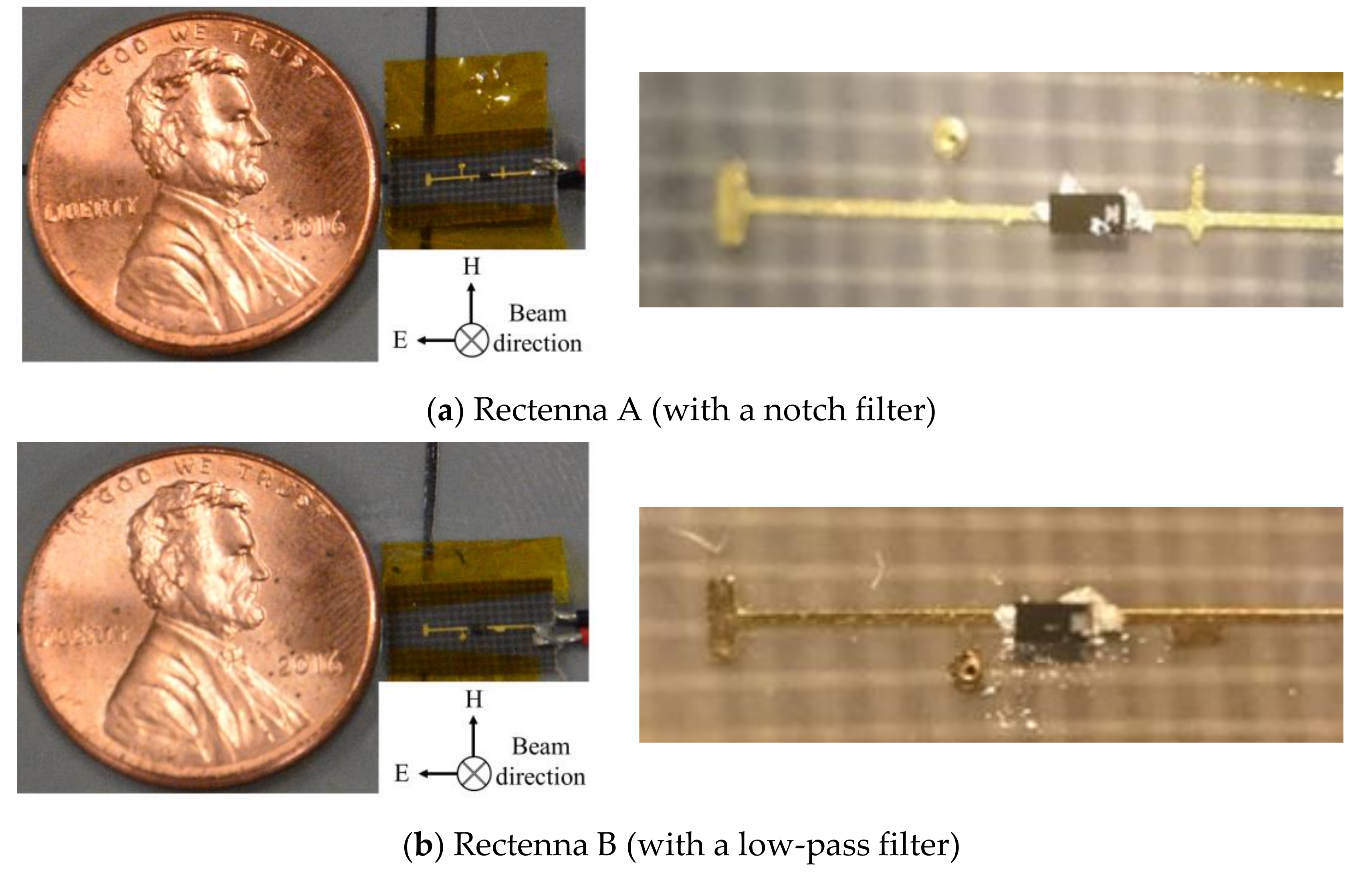
The 303 GHz rectenna structure is shown in Figure 20. The 303 GHz rectenna made of MSL and used two filter types of Rectenna A (with a notch filter) and Rectenna B (with a low-pass filter). Rectennas comprise a patch antenna and the single series structure with the diodes connected in series. The Electromagnetic field simulators of EMPro and ADS (Keysight Technologies Co. Ltd., Santa Rosa, CA, USA) were used for designing the antenna and rectifier circuit. The antenna and the rectifier were designed with matching impedance respectively and integrated as a rectenna. The PEFE substrate (NPC-F220A; Nippon Pillar Packing Co. Ltd., Osaka, Japan) was used. The diode (MA4E1310; Macom, Lowell, MA, USA) has the following parameters: slope resistance Rd = 7 Ω, junction capacitance Cj = 0.010 pF, forward voltage Vf = 0.70 V, and reverse breakdown voltage Vbr = 7 V. The diode was attached with high accuracy using a conductive paste and flip chip bonder. On the input side, both Rectenna A and Rectenna B have short stubs to create DC conduction and to facilitate impedance matching. On the output side, Rectenna A has a notch filter that prevents fundamental waves from flowing out to the load resistance. Rectenna B has a low pass filter that prevents the fundamental wave and higher harmonic waves from flowing out to the load resistance. For measurement of the antenna, finline and fixture were used to connect the network analyzer. The antenna gain was measured using a three-antenna method with three finline antennas of identical shape. Results show that the reflection coefficient was −18.7 dB; the antenna gain was 8.32 dBi at 303 GHz. This value was approximately equal to the calculated antenna gain of 7.89 dBi using the physical dimensions [27].
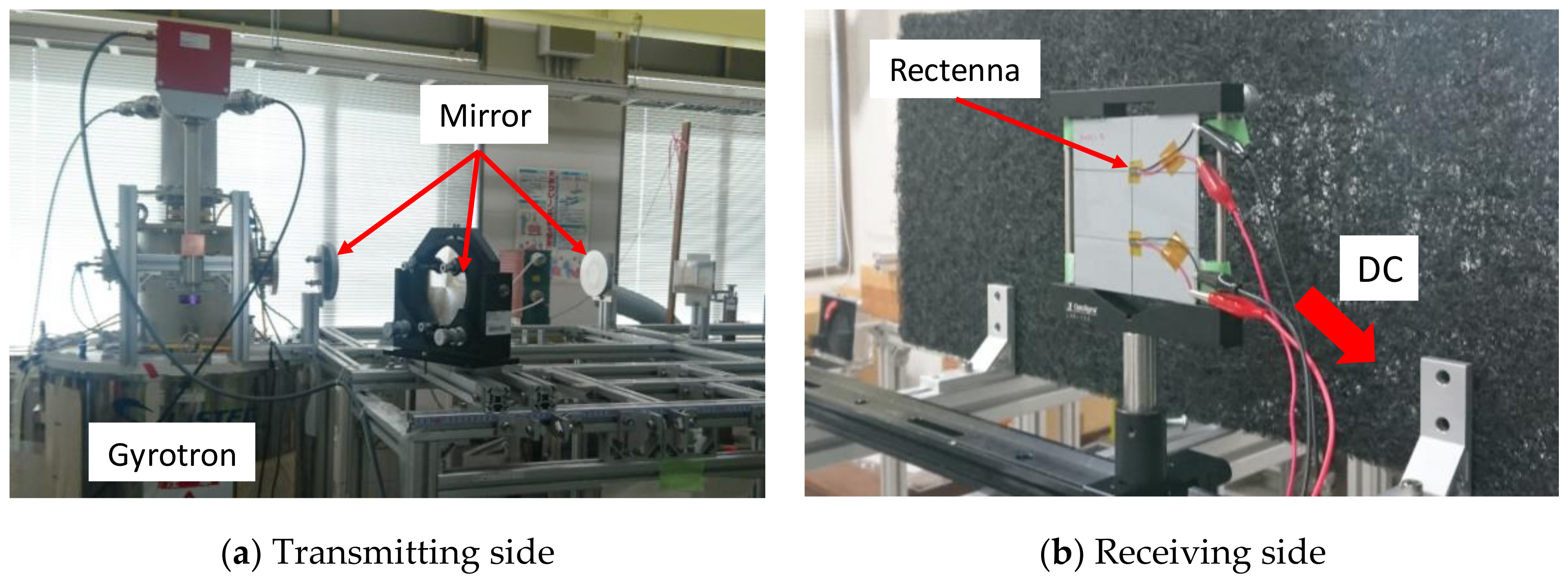
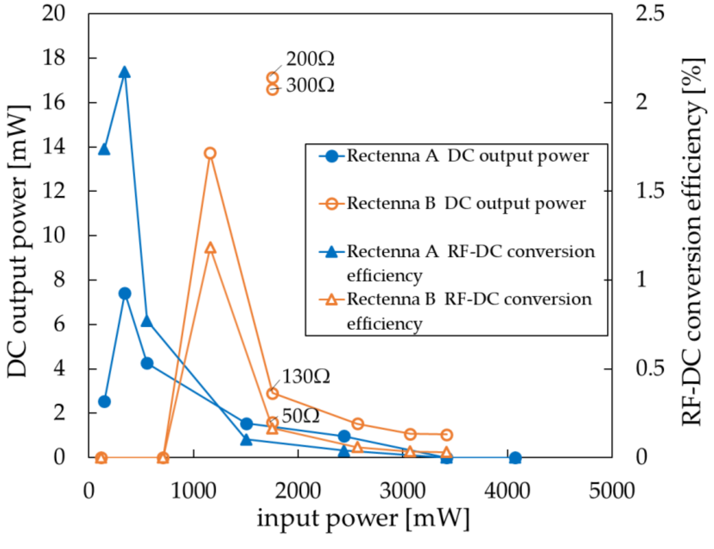
The 303 GHz gyrotron at the Fukui University Far Infrared Region Development Research Center was used for wireless power supply experiments [28,29]. The measurement setup is shown in Figure 21. The beam output power was fixed at 33.4 kW. The rectenna was installed at a point 3 m away. The rectenna was connected to the load resistance. The oscilloscope was connected via a conducting wire. Then the DC output power was evaluated. The beam profile at the 3 m points was evaluated using the IR camera. By measuring the beam profile, the power density at the rectenna insertion point was ascertained. The power input to the rectifier was estimated. The RF–DC conversion efficiency was evaluated from the change in the DC output power when the rectenna was brought close to the beam center. The measurement results are presented in Figure 22. Maximum RF–DC conversion efficiency of 2.17% was recorded for input power of 342 mW. The load resistance was 130 Ω at Rectenna A. The maximum DC output power 17.1 mW and rectenna power density 3.43 kW/m 2 when the load resistance was 200 Ω at RectennaB.

4. Conclusions

This paper introduced cutting edge millimeter wave and subterahertz wave wireless power transmission. The beam efficiency improves as the frequency becomes higher. It is suitable for long-distance high-power wireless power transmission. However, RF–DC conversion efficiency and DC output power decrease because of the increased loss in the circuit and diode. Furthermore, the oscillation source output power decreases. We discussed details of the related research which shows high power and high efficiency. Wireless power transmission at 303 GHz is the highest frequency examined in this study: the associated DC output power was 17.1 mW; the RF–DC conversion efficiency was 2.17%. Improving these results requires development of more efficient and high-breakdown voltage diodes such as GaN diodes. We hope that this paper will support the development of millimeter and subterahertz rectennas and engender the realization of long-distance, high-power wireless power transmission for use in applications such as space solar power systems and power supplies for UAVs.

Author Contributions

Writing, S.M.; Supervision, K.S.; Funding Acquisition, K.S.

Funding

This research was funded by a Japan Society for the Promotion of Science Grant-in-Aid for Scientific Research by young researchers grant number (B) No. 16 K 18306.

Conflicts of Interest

The authors declare no conflict of interest.

References

  1. Shinohara, N. Recent Wireless Power Transfer Technologies via Radio Waves; River Publishers: Gistrup, Denmark, 2018. [Google Scholar]
  2. Ye, J.; Yang, C.; Zhang, Y. Design and experiment of a rectenna array base on GaAs transistor for microwave power transmission. In Proceedings of the 2016 IEEE International Conference on Microwave and Millimeter Wave Technology (ICMMT), Beijing, China, 5–8 June 2016. [Google Scholar]
  3. Suh, Y.H.; Chang, K. A high efficiency dual-frequency rectenna for 2.45- and 5.8-GHz wireless power transmission. IEEE Trans. Microw. Theory Tech. 2002, 50, 1784–1789. [Google Scholar] [CrossRef]
  4. Yoo, T.W.; Chang, K. Theoretical and Experimental Development of 10 and 35 GHz Rectennas. IEEE Trans. Microw. Theory Tech. 1992, 40, 1259–1266. [Google Scholar] [CrossRef]
  5. Nakamura, M.; Yamaguchi, Y.; Tsuru, M.; Aihara, Y.; Yamamoto, A.; Homma, Y.; Taniguchi, E. Prototype of 5.8 GHz-band high efficiency rectifier with a high breakdown voltage GaAs SBD. In Proceeding of the Institute of Electronics, Information and Communication engineers, Minato-ku, Tokyo, Japan, 16–17 April 2015; Volume 115, pp. 21–25. [Google Scholar]
  6. Yang, X.; Xu, J.; Xu, D.; Xu, C. X-band circularly polarized rectennas for microwave power transmission applications. J. Electron. (China) 2008, 25, 389. [Google Scholar] [CrossRef]
  7. Hatano, K.; Shinohara, N.; Seki, T.; Kawashima, M. Development of improved 24 GHz-band class-F load rectennas. In Proceedings of the 2012 IEEE MTT-S International Microwave Workshop Series on Innovative Wireless Power Transmission: Technologies, Systems, and Applications (IMWS), IMWS-IWPT 2012, Kyoto, Japan, 10–11 May 2012; pp. 163–166. [Google Scholar]
  8. Koert, P.; Cha, J.T. Millimeter wave technology for spacepower beaming. IEEE Trans. Microwave Theory Tech. 1992, 40, 1251–1258. [Google Scholar] [CrossRef]
  9. Mavaddat, A.; Armaki, S.H.M.; Erfanian, A.R. Millimeter-Wave Energy Harvesting Using Microstrip Patch Antenna Array. IEEE Antennas Wirel. Propag. Lett. 2015, 14, 515–518. [Google Scholar] [CrossRef]
  10. Nariman, M.; Shirinfar, F.; Pamarti, S.; Rofougaran, A.; De Flaviis, F. High efficiency Millimeter-Wave Energy-Harvesting Systems with Milliwatt-Level Output Power. IEEE Trans. Circuits Syst. Express Briefs 2017, 64, 605–609. [Google Scholar] [CrossRef]
  11. Kamalinejad, P.; Mahapatra, C.; Sheng, Z.; Mirabbasi, S.; Leung, V.C.; Guan, Y.L. Wireless energy harvesting for the Internet of Things. IEEE Commun. Mag. 2015, 53, 102–108. [Google Scholar] [CrossRef] [Green Version]
  12. Vamvakas, P.; Tsiropoulou, E.E.; Vomvas, M.; Papavassiliou, S. Adaptive power management in wireless powered communication networks: A user-centric approach. In Proceedings of the 2017 IEEE 38th Sarnoff Symposium, Newark, NJ, USA, 18–20 September 2017. [Google Scholar]
  13. Gao, H.; Matters-Kammerer, M.; Harpe, P.; Milosevic, D.; Johannsen, U.; Roermund, A.V.; Baltus, P. A 71GHz RF energy harvesting tag with 8% efficiency for wireless temperature sensors in 65 nm CMOS. In Proceedings of the 2013 IEEE Radio Frequency Integrated Circuits Symposium (RFIC), Seattle, WA, USA, 2–4 June 2013. [Google Scholar]
  14. Hemour, S.; Lorenz, C.H.P.; Wu, K. Small-footprint wideband 94 GHz rectifier for swarm micro-robotics. In Proceedings of the 2015 IEEE MTT-S International Microwave Symposium (IMS), Phoenix, AZ, USA, 17–22 May 2015; Volume I, pp. 5–8. [Google Scholar]
  15. Chiou, H.-K.; Chen, I.-S. High efficiency Dual-Band On-Chip Rectenna for 35- and 94-GHz Wireless Power Transmission in 0.13-μm CMOS Technology. IEEE Trans. Microw. Theory Tech 2010, 58, 3598–3606. [Google Scholar]
  16. Weissman, N.; Jameson, S.; Socher, E. W-Band CMOS On-Chip Energy Harvester and Rectenna. In Proceedings of the 2014 IEEE MTT-S International Microwave Symposium (IMS2014), Tampa, FL, USA, 1–6 June 2014. [Google Scholar]
  17. Hatano, K.; Shinohara, N.; Mitani, T.; Seki, T.; Kawashima, M. Development of 24 GHz-Band MMIC Rectenna. In Proceedings of the 2013 IEEE Radio and Wireless Symposium (RWS 2013), Austin, TX, USA, 20–23 January 2013; Volume 50, pp. 199–201. [Google Scholar]
  18. Komurasaki, K.M.K.; Hatakeyama, W.; Okamoto, Y.; Minakawa, S.; Suzuki, M.; Shimamura, K.; Mizushima, A.; Fujiwara, K.; Yamaoka, H. Microstrip antenna and rectifier for wireless power transfer at 94 GHz. In Proceedings of the 2017 IEEE Wireless Power Transfer Conference (WPTC), Taipei, Taiwan, 10–12 May 2017; pp. 1–3. [Google Scholar]
  19. Trew, R.J. SiC and GaN Transistors—Is There One Winner for Microwave Power Applications? Proc. IEEE 2002, 90, 1032–1047. [Google Scholar] [CrossRef]
  20. Dickinson, R.M. Power in the sky: Requirements for microwave wireless power beamers for powering high-altitude platforms. IEEE Microwave Mag. 2013, 14, 36–47. [Google Scholar] [CrossRef]
  21. Thumm, M. State-of-the-Art of High Power Gyro-Device and Free Electron Masers; KIT Scientific Reports 7735; KIT Scientific Publishing: Karlsruhe, Germany, 2017; p. 7735. [Google Scholar]
  22. Etinger, A.; Pilossof, M.; Litvak, B.; Hardon, D.; Einat, M.; Kapilevich, B.; Pinhasi, Y. Characterization of a Schottky Diode Rectenna for Millimeter Wave Power Beaming Us-ing High Power Radiation Sources. Acta Phys. Pol. A 2017, 131, 1280–1284. [Google Scholar] [CrossRef]
  23. Suzuki, M.; Matsukura, M.; Mizojiri, S.; Shimamura, K.; Yokota, S.; Kariya, T.; Minami, R. Consideration of long distance WPT using 28 GHz gyrotron. Space Sol. Power Syst. 2018, 3, 45–48. (In Japanese) [Google Scholar]
  24. Mizojiri, S.; Shimamura, K.; Fukunari, M.; Minakawa, S.; Yokota, S.; Yamaguchi, Y.; Tatematsu, Y.; Saito, T. Subterahertz Wireless Power Transmission Using 303-GHz Rectenna and 300-kW-Class Gyrotron. IEEE Microw. Wirel. Components Lett. 2018, 28, 834–836. [Google Scholar] [CrossRef]
  25. Kariya, T.; Imai, T.; Minami, R. Development of High Power Gyrotron for Nuclear Fusion Reactor. J. Plasma Fusion Res. 2017, 93, 146–149. [Google Scholar]
  26. Fujiwara, K.; Kobayashi, T. Low-cost W-band frequency converter with broad-band waveguide-to-microstrip transducer. In Proceedings of the 2016 Global Symposium on Millimeter Waves (GSMM) & ESA Workshop on Millimetre Wave Technology and Applications, Espoo, Finland, 6–8 June 2016; pp. 1–4. [Google Scholar]
  27. Volakis, J.L. Antenna Engineering Handbook, 4th ed.; McGraw-Hill Education: New York, NY, USA, 2017. [Google Scholar]
  28. Yamaguchi, Y.; Kasa, J.; Saito, T.; Tatematsu, Y.; Kotera, M.; Kubo, S.; Shimozuma, T.; Tanaka, K.; Nishiura, M. High Power 303 GHz gyrotron for CTS in LHD. J. Instrum. 2015, 10, C10002. [Google Scholar] [CrossRef]
  29. Saito, T.; Yamaguchi, Y.; Tatematsu, Y.; Fukunari, M.; Hirobe, T.; Tanaka, S.; Shinbayashi, R.; Shimozuma, T.; Kubo, S.; Tanaka, K.; et al. Development of 300 GHz Band Gyrotron for Collective Thomson Scattering Diagnostics in the Large Helical Device. Plasma Fusion Res. 2017, 12, 126013. [Google Scholar] [CrossRef]
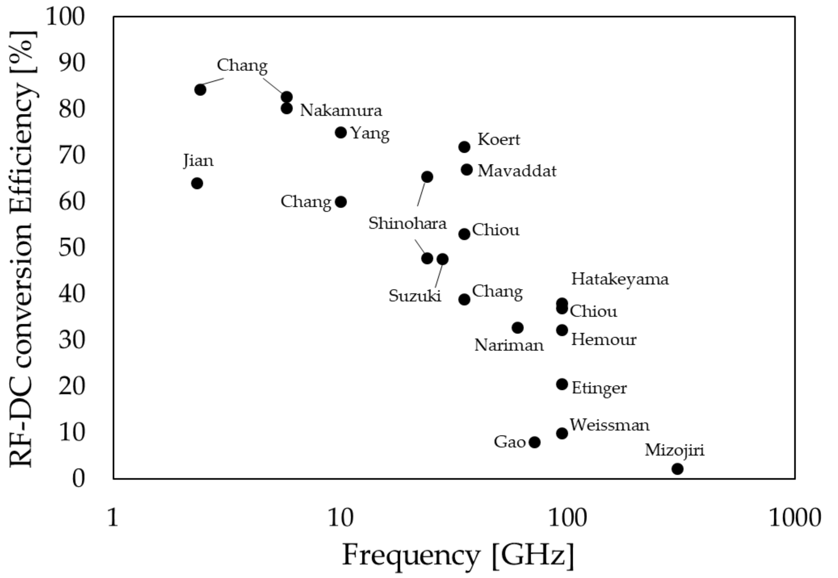
Figure 1. Earlier reports of studies examining rectenna RF–DC conversion efficiency for frequency [2,3,4,5,6,7,8,9,10,13,14,15,16,17,18,22,23,24].
Applsci 08 02653 g001
Figure 2. Earlier reports of studies assessing rectenna DC output power for frequency [2,3,4,5,6,9,10,13,14,15,16,17,18,22,23,24].
Applsci 08 02653 g002
Figure 3. Earlier reports of studies examining rectenna power density for frequency [2,4,5,14,15,16,17,18,22,23,24].
Applsci 08 02653 g003
Figure 4. Schematic diagram showing the oscillation source output range for frequencies [19].
Applsci 08 02653 g004
Figure 5. Conceptual diagram of power transmission efficiency in wireless power transmission.
Applsci 08 02653 g005
Figure 6. 28 GHz rectenna: (a) antenna and (b) rectifier.
Applsci 08 02653 g006
Figure 7. 28 GHz antenna: (a) S11 and (b) radiation pattern.
Applsci 08 02653 g007
Figure 8. 28 GHz rectifier RF–DC conversion efficiency and DC output power
Applsci 08 02653 g008
Figure 9. 28 GHz back feed structure of antenna and rectifier.
Applsci 08 02653 g009
Figure 10. 28 GHz 25 array rectenna: (a) 25 array antenna and (b) 25 array rectifier
Applsci 08 02653 g010
Figure 11. Experimental system of wireless power transmission using 28 GHz gyrotron: (a) receiving side and (b) transmitting side.
Applsci 08 02653 g011
Figure 12. 25 array rectenna DC output power in a gyrotron WPT experiment.
Applsci 08 02653 g012
Figure 13. Circuit fabrication method by semiconductor microfabrication 1.
Applsci 08 02653 g013
Figure 14. Circuit fabrication method by semiconductor microfabrication 2.
Applsci 08 02653 g014
Figure 15. 94 GHz rectenna: (a) rectifier and (b) rectenna.
Applsci 08 02653 g015
Figure 16. Process of MSL—to—waveguide transmission mode conversion by finline.
Applsci 08 02653 g016
Figure 17. Measurement setup of 94 GHz wireless power transmission.
Applsci 08 02653 g017
Figure 18. 94 GHz antenna (a) S11 (b) radiation pattern.
Applsci 08 02653 g018
Figure 19. 94 GHz rectifier RF–DC conversion efficiency.
Applsci 08 02653 g019
Figure 20. 303 GHz MSL rectenna: (a) rectenna A (with notch filter) and (b) rectenna B (with low-pass filter).
Applsci 08 02653 g020
Figure 21. Experimental system of wireless power transmission using a 303 GHz gyrotron: (a) transmitting side and (b) receiving side.
Applsci 08 02653 g021
Figure 22. Measurement results of 303 GHz DC output power and RF–DC conversion efficiency (line shows result at 130 Ω).
Applsci 08 02653 g022
Table 1. Characteristics of rectenna in earlier studies (MSL: Microstrip line, CPS: Coplanar slot line, SBD: Schottky barrier diode).
Reference No.Frequency
[GHz]
DC Output
[mW]
RF–DC Conversion Efficiency [%]AntennaDiode
[2]2.33201264MSL patchGaAs FET
[3]2.45/5.875.6/40.684.4/82.7CPS dipoleGaAs SBD
[5]5.8506.780.3Rectifier onlyGaAs FET
[6]9.9874.575MSL patchSBD
[7]24NA65.5NAGaAs SBD
[17]24100.647.9MSL patchMMIC
[23]28140.847.7MSL patchGaAs SBD
[4]10/35※81/46.860/39MSL dipoleGaAs SBD
[8]35NA72MSL patchGaAs SBD
[9]35.74.6967MSL patchGaAs SBD
[10]601.2232.8Grid antennaCMOS
[13]710.258MonopoleCMOS
[14]940.6532.3Bow-tie slotGaAs SBD
[15]35/94※1.6/0.953/37Taper slotCMOS
[16]940.110DipoleCMOS
[22]941520.5MSL patchMott diode
[18]943938Rectifier onlyGaAs SBD
[24]30317.12.17MSL patchGaAs SBD
※Value is not specified.
Table 2. Comparison of this work to earlier studies in K - Ka band (CPW: Coplanar waveguide, GCPW: Grounded coplanar waveguide, BPF: Band-pass filter, LPF: Low-pass filter).
Reference No.[17][15][8][4][9]This Work [23]
Frequency [GHz]2435353535.728
Transmission LineMSLSlot & GCPWMSLMSLMSLMSL
TechnologyMMICCMOS 0.13 µmDielectric BoardDuroidDuroid 5880Diclad880 (Rogers)
ArchitectureClass F load + RectifierTaper slot antenna+ Transition + BPF + RectifierMSL patch antenna + RectifierDipole + LPF + RectifierMSL patch 4 × 4 array + LPF + RectifierMSL patch + Class F load + Rectifier
DiodeNACMOS Shottky diodeGaAs SBDGaAs SBD
(DMK6606Alpha)
GaAs SBD (MA4E1317 MACOM)GaAsSBD (MA4E1317 MACOM)
Antenna Gain [dBi]-7.4NANA199.0
OscillatorNANetwork AnalyzerGunn Oscillator & TWTAGunn OscillatorSignal GeneratorGyrotron
Oscillator Output Power [W]NA~20 dBm~5000.2~20 dBm52,900
Rectenna DC Output Power [mW]100.61.6NA46.84.691050
RF-DC Conversion Efficiency [%]47.95372396747.7
Load Resistance [Ω]120100NA1001000130
Rectenna size [mm2]1 × 2.31 × 2.9120 × 1207.11 × 7.1122 × 4210×20
Rectenna Power density [kW/m2]2.380.55-0.9250.0050.857
Table 3. Comparison of this work to earlier studies in W—mm band.
Reference No.[14][15][16][22]This Work [18]This Work [24]
Frequency [GHz]9494949494303
Transmission LineCPWSlot & GCPWMSLMSLMSLMSL
TechnologyAluminaCMOS 0.13 µmCMOS 65 nmDuroid 5880NPC-F220A (Nippon Pillar Packing)NPC-F220A (Nippon Pillar Packing)
ArchitectureBow-tie slot antenna + RectifierTaper slot antenna + Transition + BPF + RectifierDipole + step-up
Transformer + Rectifier
MSL patch 2 × 2 array + RectifierNotch filter + RectifierMSL patch + Notch or Low-pass filter + Rectifier
DiodeGaAs SBD
(Virginia diode VDI ZDB)
CMOS Shottky diodeCMOSMott diodeGaAs SBD
(MA4E1310 MACOM)
GaAs SBD
(MA4E1310 MACOM)
Antenna Gain [dBi]NA6.5NA12-8.32
OscillatorKlystronNetwork Analyzersolid-state W-band sourceGyrotronsolid-state W-band sourceGyrotron
Oscillator Output Power [W]~100~20 dBm0.14~5000~0.433,400
Rectenna DC Output Power [mW]0.650.90.1153917.1
RF-DC Conversion Efficiency [%]32.3371020.5382.17
Load Resistance [Ω]4001005000200130130
Rectenna size [mm2]5.621 × 2.90.48※5.1 × 9.43.6 × 51 × 5
Rectenna Power density [kW/m2]0.170.310.0380.32.383.43
※ Value is not specified.
Table 4. Comparison of measurement results, transmission efficiency to theoretical efficiency in respective conditions: 900 mm without CA, 900 mm with CA, and 1350 mm with CA
No.DistanceCAMax
ηtotal
Theoretical
ηtotalηtrηreηaprηRFDC
900 mm×2.30%2.35%100%32.6%15.1%47.7%
900 mm1.07%3.45%83.2%57.5%15.1%47.7%
1350 mm0.12%3.22%83.2%53.7%15.1%47.7%