Article

Effects of Vehicular Communication on Risk Assessment in Automated Driving Vehicles

1
Department of Mechanical Engineering, College of Engineering, Republic of Korea Naval Academy, Changwon-si 51704, Korea
2
Department of Computer Science, College of Natural Science, Republic of Korea Naval Academy, Changwon-si 51704, Korea
3
Department of Electronic Engineering, College of Convergence Technology, Korea National University of Transportation, Chungju-si 27469, Korea
*
Author to whom correspondence should be addressed.
Appl. Sci. 2018, 8(12), 2632; https://doi.org/10.3390/app8122632
Submission received: 6 December 2018 / Revised: 12 December 2018 / Accepted: 13 December 2018 / Published: 15 December 2018
(This article belongs to the Special Issue Unmanned Aerial Vehicles (UAVs))

Abstract

:

Featured Application

Vehicular communication is expected to overcome conventional in-vehicle sensor limitations such as ranging and accuracy. In addition, this will enhance the perception and decision performance of automated driving vehicle in terms of guaranteed safety.

Abstract

This paper proposes a human-centered risk assessment algorithm designed to find the intervention moment of drive mode and active safety mode while monitoring threat vehicles ahead to overcome effects of vehicular communication on risk assessment in automated driving vehicle. Although a conventional radar system is known to be best fitted on-board ranging sensor in terms of longitudinal safety, it is generally not enough for a reliable automated driving because of sensing uncertainty of the traffic environments and incomplete perception results due to sensor limitations. This can be overcome by implementing vehicle-to-vehicle (V2V) communication which provides complementary source of target vehicle’s dynamic behavior. Using V2V communication with vehicle internal and surround information obtained from the on-board sensor system, future vehicle motion has been predicted. With accurately predicted motion of a remote vehicle, a collision risk and the automated drive mode are determined by incorporating human factor. Effects of the V2V communication on a human-centered risk assessment algorithm have been investigated through a safe triangle analysis. The computer simulation studies have been conducted in order to validate the performance of the proposed algorithm. It has been shown that the V2V communication with the proposed risk assessment algorithm allows a faster drive mode decision and active safety intervention moment.

1. Introduction

With a significant development in sensors, actuators and other technologies related to vehicle-to-vehicle (V2V) communication technologies, numerous developments in safety systems have been achieved during the last decade. Intelligent systems based on on-board perception/detection devices have contributed to improve road safety [1]. The next step in the development of vehicle safety technology points toward vehicle-to-vehicle (V2V) communications to obtain more extensive and reliable information about vehicles in the surrounding area, representing cooperative intelligent transportation systems (C-ITS). Research projects have been conducted throughout the world to define the requirements for an appropriate vehicular communication system and its possible applications [2].
While the in-vehicle sensors can enable a limited level of safety functionalities without the use of inter-vehicle communication, the benefits that V2X communication can bring are widely known by many automobile manufacturers, and they are the result of collaborations with the mobile industry. Toyota and Lexus have commercialized vehicles equipped with V2X communication technology from 2015 on the road in Japan. This technology provides drivers with useful and detailed surrounding vehicle and traffic signal information. In addition, they aim to deploy the technology with Dedicated Short-Range Communications (DSRC) systems on vehicles sold in the United States starting in 2021 [3]. Audi, Ford and Qualcomm announced cellular-based vehicular communication technology (C-V2X) operating across vehicles from different manufacturers. A demonstration has been performed to show the effectiveness of using C-V2X technology on the ITS spectrum in order to avoid vehicle-to-vehicle collision and improved road safety [4].
Effects of V2X communication on the automated vehicle safety have been investigated through information fusion and risk assessment. Shin et al. [5] proposed a human-centered risk assessment algorithm using V2V communication in order to determine a proper intervention timing of active safety system.
A host vehicle reduces the chances of perception error and uncertainty during a sudden deceleration due to the fact that V2V communication allows a host vehicle to receive the internal sensor information of a remote vehicle and, to compute more accurate prediction. It overcomes the estimation error of a convectional radar-based advanced driver assistant system (ADAS).
For fully automated driving, however, a drive mode decision function with guaranteed safety has to be integrated to threat assessment algorithm. For a safety-critical cyber-physical system of an automated electric vehicle, in [6], an artificial-neural-network (ANN)-based estimation method is announced for an accurate observation of the brake pressure of the vehicle. The ANN-based machine learning framework is used to quantitatively estimate the brake pressure of the vehicle, and it has great potential to achieve a sensorless design of the braking control system. The guaranteed safety is also crucial for a lane change decision in fully automated driving. Previous researches are analyzed a pattern of lane change of human driver data to determine lane change timing [7]. The learning-based approach for lane change using neural network to predict the maneuver trajectory [8], and a fuzzy logic for solving the modeling lane change decision making problems [9] were proposed.
Since lane changing for an automated driving system requires predicting traffic by the host vehicle, a probabilistic threat assessment approach was proposed by successfully implementing a stopping sight distance [5]. To decide on the active safety control intervention moment, collision risk and human reaction time, which is inspired by stopping sight distance, are determined. Active safety systems of automated vehicle have become more intelligent incorporating human-sense, and this enhances driver acceptance. To realize drive mode decisions with high driver acceptance, the concept of decision sight distance can be considered for continuous risk assessment [10].
In this paper, the main contribution is the merging between V2V communication and a vehicle-based sensor as radar in order to get most valuable data for safety in longitudinal collision risk. The idea to incorporate such integration with a user-centered algorithm for predictive drivers’ behaviors, in the intention to include a human-like behavior in the automation, is the other contribution.
Section 2 demonstrates the information fusion and fundamental descriptions for a radar, camera and the V2V communication are discussed. In Section 3, the threat assessment method describing a safe triangle analysis is demonstrated. The risk assessment algorithm with the V2V communication is investigated through simulation studies in Section 4. Finally, conclusions are provided in Section 5.

2. Sensor Characteristics and Information Fusion

The characteristics for vehicular communication and conventional local sensor systems are described. The backgrounds for radar and its sensing characteristics for application to intelligent vehicle are demonstrated. For a longitudinal safety, automotive radar is known to be the best fitted vehicular surround sensing technology with respect to functionality, robustness, reliability, dependence on weather conditions etc. [11]. Its performance has been evaluated by comparing with the camera (vision sensor). However, due to the inherent uncertainty of the traffic environments and incomplete knowledge because of sensor limitations, V2V communication has been widely considered to provide the host vehicle with more enriched target information by fusing with the radar sensor. In this section, the advantages of radar sensor have been presented by experimentally comparing with the camera. The V2V communication information is explained as well and the comparison results of the DSRC with long-term evolution-vehicle (LTE-V) technologies are provided. In addition, a high-level data fusion architecture of radar and V2V communication is described.

2.1. On-board Ranging Sensors

The radar is currently the most widely adopted sensing technology for automotive ranging applications. The radio detection and ranging (RADAR) is a system that uses electromagnetic waves to identify the range, direction, or speed of both moving and fixed objects such as aircraft, ships, motor vehicles, weather formations, and terrain. In this technology, the distance from the object is calculated through the echoes that are sent back from the object. The determination of the position of an object is done through the time-of-flight and angle measurement. In process of time-of-flight measurements, electromagnetic energy is sent toward objects and the returning echoes are observed. The measured time difference and the speed of the signal allow calculating the distance to the object. The Speed measurement is made through the Doppler effect. The base of the Doppler effect is change of wavelength due to the changing gap between waves. Although the amount of signal returned is tiny, radio signals can easily be detected and amplified. RADAR sensors are also known to have sufficient robustness to function reliably under harsh environmental conditions for extended periods of time [12].
Vision sensor systems use one or several cameras together with a microprocessor to perform image processing. Since they operate in the visible light region, their capabilities are similar to that of our own eyes. A camera-based sensor is used to detect car/obstacle in front of the subject vehicle. Camera-based longitudinal safety systems are typically used for medium range, medium field of view detection. The camera system can be charge coupled device (CCD)-based or Complementary Metal Oxide Semiconductor (CMOS)-based [13].
In their basic single camera configuration, video imagers struggle to provide ranging information. However, using the principle of triangulation coupled to obstacle recognition routines, the images viewed by camera systems may be processed to facilitate identification of obstacles and their range. Such systems provide good obstacle and environmental recognition using non-intrusive means.
Cameras are able to provide information about target position for slow moving vehicles. They are capable of detecting targets even when placed at a distance from the region to be monitored. However, cameras placed in this fashion provide poor longitudinal position accuracy.
An experiment was performed by using the test vehicle which is equipped with radar and vision sensor systems for measuring the range and range-rate to the proceeding vehicle under vehicle following situation in order to evaluate longitudinal safety. Data acquisition is performed at various ranges and relative velocities with constant speed of the target vehicle. In many cases, due to road curvatures, other vehicles, uneven road surfaces relative lateral position and lateral movement, the measurement range distribution might be different. Also, the exact reflection point is uncertain since the azimuth angle is not very exact, so for medium distances the main reflection point may be located on different parts of the car. Hence, test data was collected in the test road without other vehicle or obstacle.
The lateral displacement of the longitudinal centerline of the subject vehicle relative to the longitudinal centerline of the target vehicle kept less than 0 m. The subject vehicle cruises behind the preceding vehicles in initial vehicle speed. The initial speed and range of subject vehicle (SV) and preceding vehicle (PV) are set to be Table 1. To validate the sensor detection performance, the GPS-based device, RT-Range, is used to measure the reference of the range and range rate data. The RT-Range device uses RT-3000 which is precision GPS device, and is equipped on the test vehicle respectively.
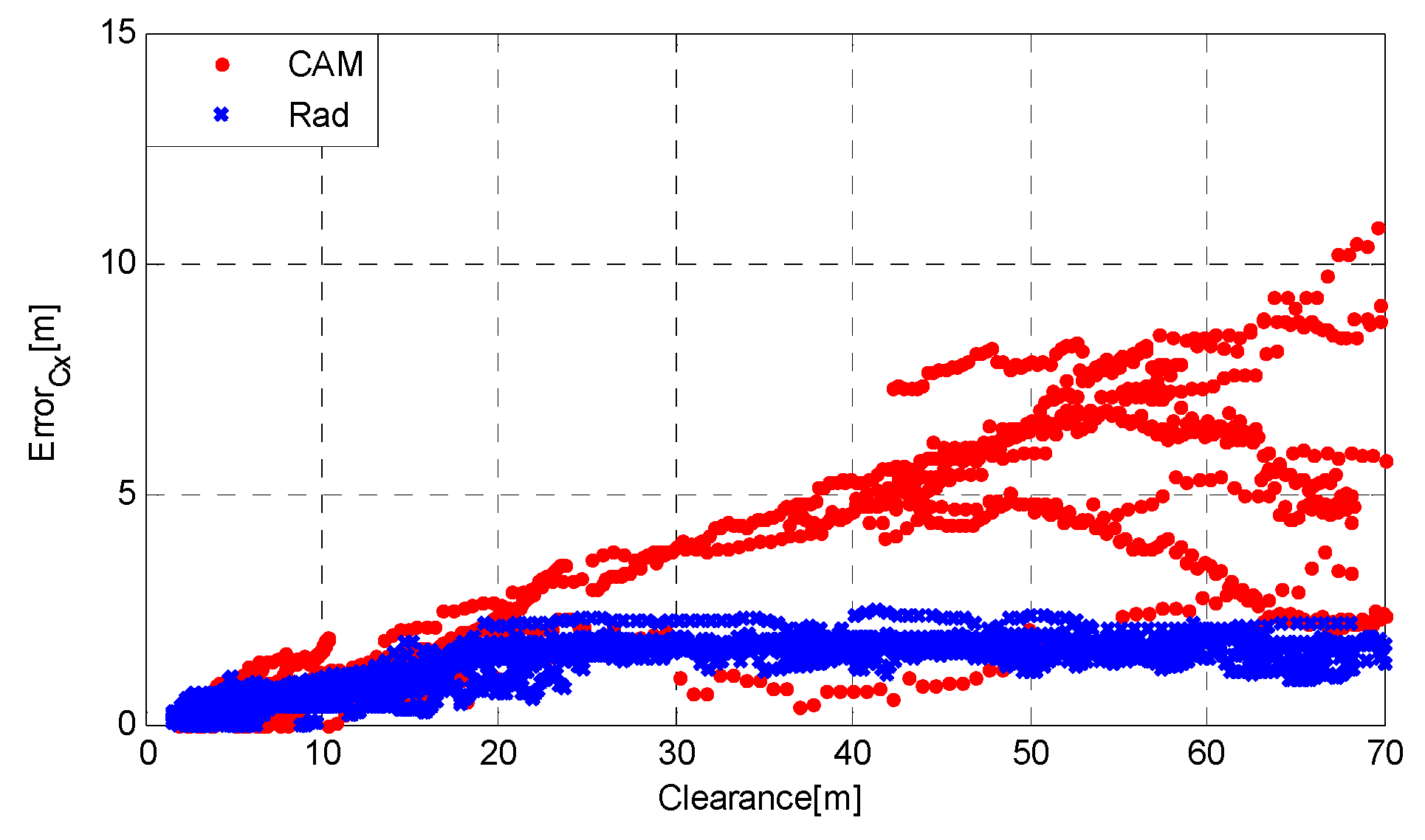
In Figure 1, range error in vehicle test is depicted. As shown in Figure 1, vision sensor and radar sensor have similar detection error pattern within the 10 m range. On the other hand, range error in vehicle test is depicted. As shown in Figure 1, vision sensor and radar sensor have similar detection error pattern within the 10 m range. On the other hand, range error of the vision sensor is bigger than the radar sensors over the 10 m range situation. In terms of range and speed measurement for application to vehicle longitudinal safety, radar data demonstrate more accurate results compared to camera.

2.2. Vehicular Communication

Connected vehicle technologies evolved from the 1980s with the widely known project called the California Partners for Advanced Transit and Highways (PATH) project. Multi vehicles made by Ford Motor Company are platooned together with the longitudinal control using wireless LAN communication systems as well as radar, throttle, brake actuators. In 1992, the it was remembered that the first ever platooning experiments and demonstrations on the highway were performed successfully.
Volvo demonstrated vehicular wireless communication technology for the project named Safe Road Trains for the Environment (SARTRE) in 2012. In this demonstration, a Volvo FH truck drove around the test track, followed by other Volvo cars with quite close inter-distance. Although the inter-distance between the vehicles was smaller than when a human drives, it is much safer since the computer responds to even trivial or small change is detected. For the demonstration, V2V communication with 802.11 p is used for the main communication channel.
In 2013, Hyundai Mobis and Seoul National University demonstrated V2X communication enabled autonomous driving technologies in Korea, at the ITS test site in Hwaseong. Two Hyundai Sonatas from Mobis and one Hyudai Azera are used to perform several scenarios with Cohda MK5 wireless communication device. The scenarios include Intersection Management Assist (IMA), Electronic Emergency Brake Light and Blind Spot Warning.
Dedicated Short Range Communications (DSRC) is one of the researching hotspots, and it has already the become V2X communication standard in some areas, such as America and the Europe. Meanwhile, the performance of DSRC in non Line-of-Sight scenarios is quite terrible and the performance declines rapidly when the number of vehicles increases to some threshold. These shortcomings of DSRC are widely admitted by researchers. Thus, LTE-V is one of the Cellular Vehicle-to-Everything (C-V2X) direct communication technologies, and which might take place of DSRC.
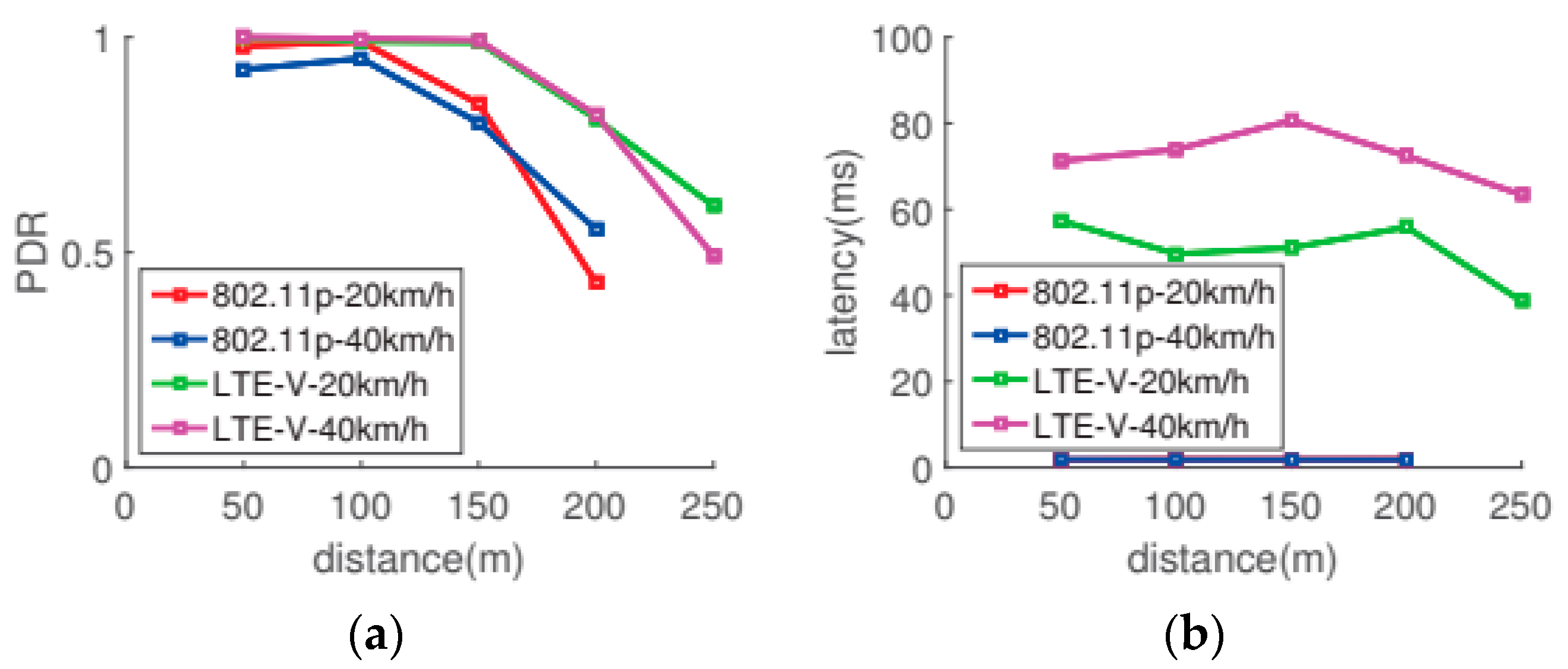
To validate the performance of LTE-V, Shi et al. [14] conducted an experiment with two cars at an intersection. During the experiment, messages were sent 10 Hz and two conclusions are derived: PDR (Package Deliver Rate) and latency, which are shown in Figure 2.
Since safety related applications for V2V communication are susceptible to even a bit longer latencies, this could cause fatal accidents when an emergency braking situation. To guarantee traffic safety, when a control command, braking for example, is sent to a car, the car must receive the command within 1 ms.
The latency of a 4th Generation (4G) network, which is a sort of LTE-V, cannot meet this requirement. With the latency of a 4G network, a car driving at 100 km/h still moves 1.4 m from the time it finds an obstacle to the time when the braking command is executed. Under the same condition, with the latency on a 5G network, the car will move just 2.8 cm, and this performance is comparable with the standard of an anti-lock braking system (ABS) [15].
A 5G-based C-V2X communication is introduced by Huawei, LG and Qualcomm. Since 5G-enabled communication has ultra-low latency of 1 ms with the average communication speeds of 3.6G bit/s using 100 MHz bandwidth, safety related vehicle control applications can be considered. As the size of the data are getting bigger, infrastructure-based remote computing is needed and the 5G communication is applicable for the transmission and receipt of big data. Infrastructure-based computation means using a cloud or edge computing. Two computing methods have their own advantages and disadvantages. Cloud computing has no limitation of computing power; however, it has more likely to experience slow internet connection issues. Edge computing is much faster than cloud computing; however, the computational resource is limited or is hard to expand.
Korea Telecom (KT), one of the cellular communication providers in Korea, demonstrated Level 3 autonomous driving technology with 5G communication. Two buses were demonstrated with the 5G connected technology by exchanging their driving information as well as video that shows blinded front traffic situation. This connected technology-based service is promising for the future connected automated driving since it can stabilize Internet-based service which is going to be applied for the safety related functions for the intelligent vehicle. Connected automated driving technology needs to offer less than 10 ms of latencies with less than 1% of packet error rate. This allows the autonomous vehicle to drive safely without any issue of communication error.
In the future, the C-V2X solution and the convention ADAS local sensors are to be combined for 100% of guaranteed safety. Even though we use the edge computing with 5G communication, there are still chances for communication errors. This still makes us use local sensor-based safety functions in terms of emergency situations such as emergency driving situations. For normal driving situations, infrastructure computing (cloud or edge) based-based autonomous driving can be performed cooperation with other surround vehicles. This allows the vehicles to drive much safer and much smoother.

2.3. Information Fusion of Radar and V2V Communication

The V2V communication, however, has several limitations when it applies to automated driving. GPS receiver has poor position estimation performance when it enters a tunnel or urban shadowing area due to low signal strength and multipath propagation error.
These situations cause degradation of target tracking performance which bring about dead-reckoning mode, and consequently producing larger errors. Depending on the transmission power and receiver sensitivity, transmission messages can be received up to a distance of 1 km [16]. However, obstacles, such as buildings in urban environments, the surrounding topography in rural environments or big trucks on highways might block the wireless signal and thus make a communication between vehicles not possible. ITS-G5 (European standard for V2V communication) uses Carrier Sense Multiple Access with Collision Avoidance (CSMA-CA) to access the wireless channel and avoid the occurrence of packet collisions. However, in dense traffic scenarios, packet collisions occur and can lead to a drop in performance of a cooperative positioning approach [17]. Therefore information from V2V communication is often considered not to be reliable enough to initiate automated maneuvers.
On the other hand, radar (camera and LiDAR systems as well) has its own limitations. Many heuristics are applied to the object detection, which leads to a compromise between sensitivity and false positive rates. Static objects or objects in far distances are very hard to detect reliably. Despite the shortcomings in both technologies, we found they are complimentary to each other.
Radar can provide a constant passive scanning of the surrounding, catch all detection candidates and provides good relative positioning measurements. If those candidates happen to be V2V communication device equipped, the information from their DSRC messages can help to eliminate almost all uncertainties and enrich those candidates with much more additional information. In this way, we do not need to worry about the drops in V2V communication message reception and low quality of positioning from GPS.
In Figure 3, in the high level fusion architecture, all sensor information is processed at the sensor level, making possible applications which have high standard modularity and simplicity. Therefore the high level fusion is proposed and it has been successfully and well described in automotive applications, such as adaptive cruise control [18] and for other active safety feature [19].
The demonstrated high level fusion architecture for the automated driving algorithm is composed of two. One is a local filter and the other is master filter as seen in Figure 3.
For the radar data process, at a local filter, extended Kalman filters (EKF)-based interacting multiple model (IMM) has been implemented to compute the remote vehicles’ dynamic states with relative position and velocity. A state augmented estimation algorithm to compensate the communication latencies is used in the V2V communication local filter. To express dynamic motion of the remote vehicle, we derive a kinematic vehicle model. After then, to describe the remote vehicle’s CAN bus, standard measurement model is derived and the vehicle information is transmitted. The state vector of the local filter of V2V communication is derived in (1):
x r v v 2 v = [ p r v , x v 2 v p r v , y v 2 v θ r v v 2 v v r v , x v 2 v γ r v v 2 v a r v , x v 2 v γ ˙ r v v 2 v ] T
Here subscript r v is remote vehicle, p is the relative position between two vehicles, θ is the relative yaw angle between two, v is the longitudinal speed, γ is the yaw speed, a is the longitudinal speed, and γ ˙ is the derivative term of yaw speed.
In Figure 3., fusion of V2V communication track and radar track is described in the master filter. To perform a track-to-track association for the data coming from two independent sources in local filter, x ¯ r a d a r and x ¯ v 2 v , the first step is to regard how close one track is to another so that association decisions can be made. A validation region is the volume in state space where tracks are expected. This validation region is usually expressed in terms of the Mahalanobis distance.
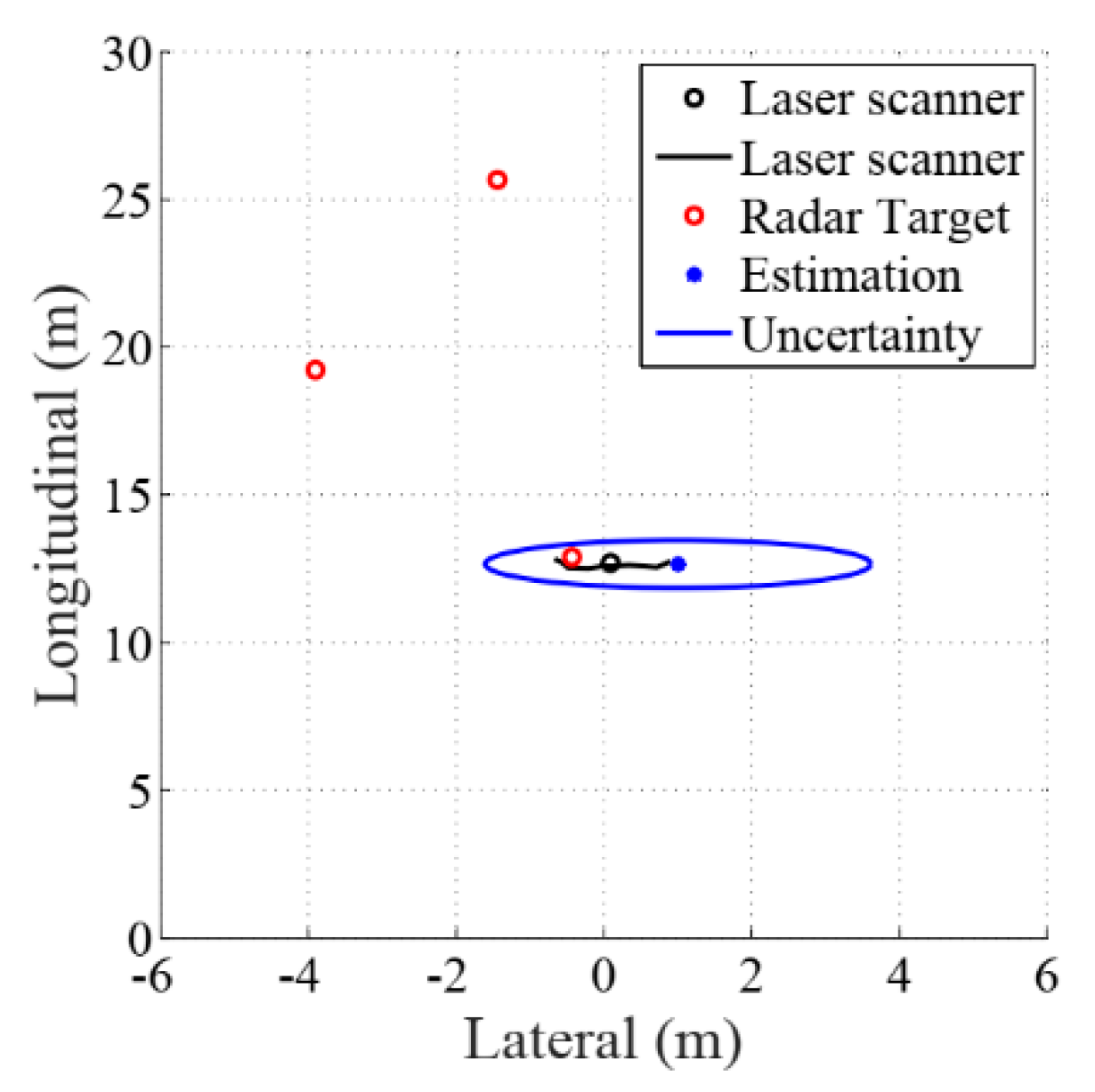
For example, Figure 4 shows an example of a radar measurement validation. The reference (true) position of the target-vehicle is shown in black line which is target vehicle trajectory. A V2V/Radar fusion result is expressed by blue dot, which is a current estimated target-vehicle location. The estimation uncertainty is shown to be a three sigma ellipse in red. The red circles are radar measurements, of which only the nearest to the current estimate are used to update the baseline. The advantage of using a validation area based on the Mahalanobis distance instead of an Euclidean distance is that it takes the uncertainty in each of state variables with different units, into account.
Given two tracks, radar and V2V with mean estimates and covariances represented by ( x ¯ r a d a r [ k ] , P ¯ r a d a r [ k ] ) and ( x ¯ v 2 v [ k ] , P ¯ v 2 v [ k ] ) , the Mahalanobis distance is defined as:
χ r a d a r , v 2 v = ( x ¯ r a d a r [ k ] x ¯ v 2 v [ k ] ) T ( P ¯ r a d a r [ k ] + P ¯ v 2 v [ k ] ) 1 ( x ¯ r a d a r [ k ] x ¯ v 2 v [ k ] )
Both the uncertainty of the state estimate and that of the measurement influence the Mahalanobis distance. The smaller these uncertainties are, the higher the associated distance. For the experimental sections, the Mahalanobis distance threshold was empirically set to 5, in order to get a good rejection of outlier radar measurements, due to other vehicles and scatter the state estimate and that of the measurement influence the Mahalanobis distance. The smaller these uncertainties are, the higher the associated distance. For the experimental sections, the Mahalanobis distance threshold was empirically set to 5, in order to get a good rejection of outlier radar measurements, due to other vehicles and scatter. Data association techniques are used for relating measurements to targets [20]. Unlike the Nearest-Neighbor approach, where only the measurement which has the smallest Mahalanobis distance to the target is used to update the measurement; in probabilistic data association all measurements in the validation region are taken into account.
3. Automated Driving Risk Assessment

It is well known that a human-centered risk assessment algorithm is beneficial to avoid collision at any speed range with a proper intervention timing of active safety function [5]. For a fully automated drive, drive mode decision function, a lane change or a lane keeping, is to be activated while ensuring safety. A decision sight distance is implemented to facilitate adequate mimicking of human senses and allows to mirror human internal states by computing human reaction time for safety and smoother operations. In this paper, the algorithm is extended to activate a drive mode decision function incorporating human reaction time based on decision sight distance. Figure 5 shows an overview on the human-centered risk assessment algorithm including two control functions: an active safety mode, and a lane change mode (drive mode decision). The proposed safe triangle analysis is based on the peak (maximum) collision probability, maxCp, and the human reaction time with respect to most probable predicted collision distance, DpmaxCp.
A safe triangle analysis is proposed to assess the risk and to decide mode intervention timing for a fully automated drive. It allows the system to decide the drive mode by avoiding the collision at any driving situation. For a longitudinal safety, the safe triangle analysis detects drive mode decision timing before active safety intervention function is activated. With the V2V communication, the area of safe triangle is enlarged due to accurate information of front vehicle dynamic states.

3.1. Risk Assessment for Drive Mode Decision

A decision sight distance (DSD) [10] is used to extend the human-centered risk assessment algorithm and it allows to determine the intervention timing of a drive mode (lane change) by considering safety and smoother operation of vehicle. The experimentally acquired and fitted data for the decision sight distance with a range of speed is described in Table 2.
The DSD is the distance required for a driver to handle the dangerous situation, select a proper velocity and path, and start and complete the required maneuver safely. A 14 s of human driver reaction time for decision sight situations incorporates the abilities of most drivers, including those of older drivers. This sight distance is for the recommended urban driving condition. As seen in Table 2, a DSD formula is described incorporating driver perception-reaction time with deceleration distance to derive the design speed.
D S D ( t ) = D r i v e r   p e r c e p t i o n r e a c t i o n   d i s t a n c e + b r a k i n g   d i s t a n c e = 0.278 v x ( t ) T r + 0.039 v x ( t ) 2 a
where,
  • D S D = r e q u i r e d   d e c i s i o n   s i g h t   d i s t a n c e   [ m ] v x = l o n g i t u d i n a l   S p e e d   [ m / s ] T r = b r a k e   r e a c t i o n   t i m e = 14   [ s ] a = d e c e l e r a t i o n   r a t e = 3.4   [ m / s 2 ]

3.2. Safe Triangle Analysis

It is widely known that the best trade-off between human reaction time and collision risk computed from the machine is proper intervention timing for active safety function. To maximize driver acceptance and vehicle safety, these two factors are considered for whole driving speed range. For a human factor, driver’s perception reaction time had been implemented and a stopping sight distance formula is introduced. The collision risk had been computed real time by finding corresponding human reaction time. This means that embedded human factor is interacting with machine which numerically computes the risky situation with Monte-Carlo simulation process. In addition, this graph is called single safety plane. Here a safe triangle is introduced in order to consider both normal and emergency driving situations. The driving situation changes many times and situation awareness is getting more important. The safe triangle includes two intervention points so that two modes are activated with proper timing.
The algorithm aims to decide a proper intervention timing of two control functions for a fully automated driving. For a longitudinal safety, the safe triangle analysis detects a drive mode decision timing before active safety intervention function is activated. It can be achieved by finding the intervention point (moment) of active safety and drive mode. Between maximum collision risk and corresponding predicted human reaction time with respect to DpmaxCp, each crossing point is a best intervention point. To improve driver acceptance while ensuring safety and driving efficiency, a human driver’s ability has to be implemented to active safety control and drive mode decision. It is well known that human reaction time and probabilistic collision risk well express a best trade-off between a human sense and automated function [5] .
In Figure 5, a remote vehicle sudden braking of 0.2 g during which a host vehicle is initially following the remote vehicle by driving 110 km/h of constant speed. Here two maximum predicted human reaction times of two control functions are set to be 2.5 and 14 s, respectively. Since previous experimental data [9,21] verified the validity of the 2.5 and 14 s as the optimal design perception-reaction time (human reaction time) for a safety and smoother operations of human-like driving. The collision probability, 0 to 100%, and predicted reaction time, 0 to 2.5 s, are corresponding to each other as described in Figure 5. More than 14 s of human reaction time describes enough of a situation for a driver to determine drive mode such as a lane keeping/changing safely. However, smaller than that demonstrates collision probability should be considered due to the fact that the driver and the safety system have to be cautious and to predict the remote vehicle’s behavior.

4. Simulation Studies: Effects of V2V Communication

We have used Matlab/Simulink 2017a which is introduced in Natick, MA, United States - (9 Mar 2017) by Mathworks, connected to Carsim8.02 software which is introduced in Ann Arbor, MI, United States (2010) by Mechanical Simulation Corporation, for our simulations in order to validate the effectiveness of the V2V communication on the automated vehicles. The human–centered risk assessment has been used for the simulation studies. It considers the intervention of two control functions and its perception performance is investigated on the safe triangle analysis. A predicted collision risk with two predicted human reaction time, and each corresponding intervention timing of two control functions are the main performance metrics. To show the over/under estimate of the conventional radar only system by comparing with the V2V communication, the predicted risk with the reaction time is implemented. The active safety intervention moment shows a delay of the decision making process.
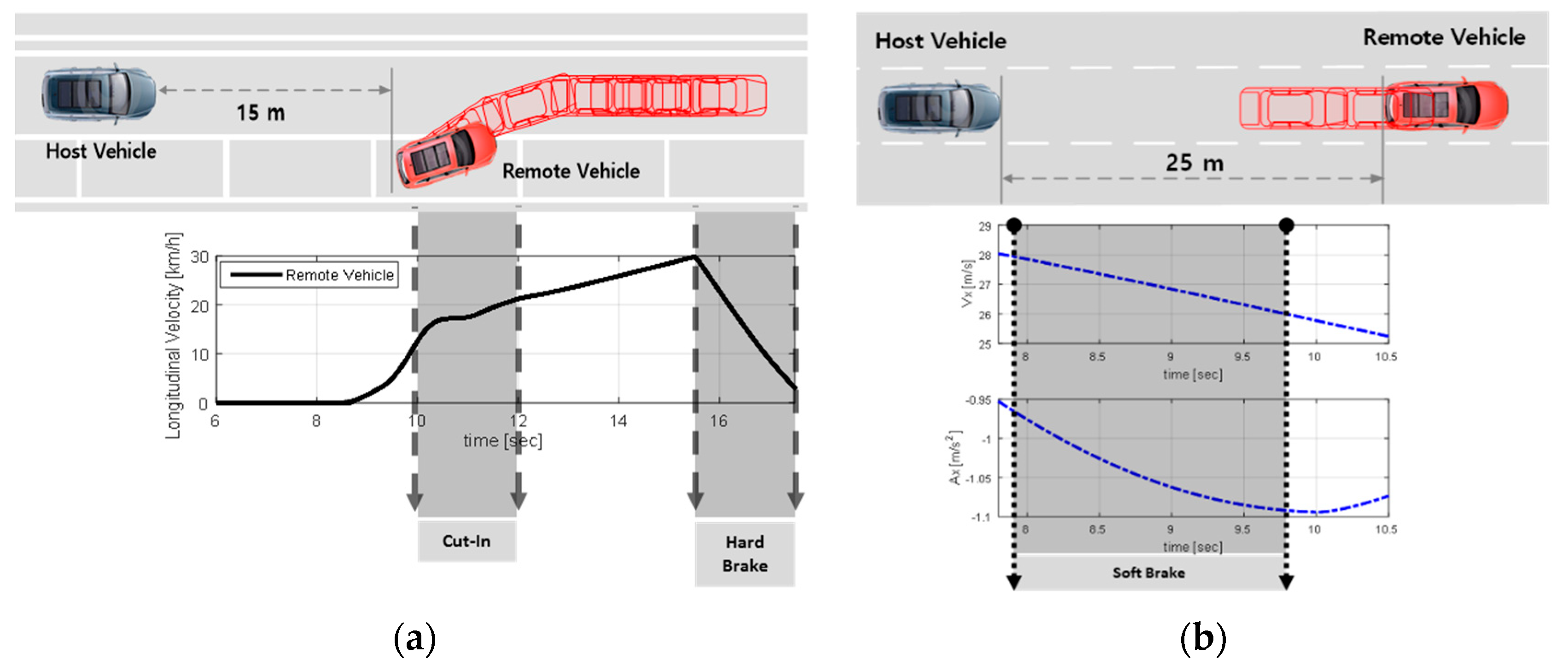
Two simulation studies are investigated in this paper. The first is the remote vehicle’s sudden braking right after the parked remote vehicle’s sudden cut in as seen in Figure 6a. In addition, Figure 6b shows the scenario for the response of the host vehicle when the preceding remote vehicle applies the hard brake on the highway.
In Figure 6a, the host vehicle is cruising at a constant speed of 30 km/h and the remote vehicle is suddenly braking right after the parked remote vehicle cutting in with the range of 15 m. As demonstrated in Figure 6a, the remote vehicle applies hard brake of 0.35 g.

4.1. Remote Vehicle Dynamic State Estimation Performance

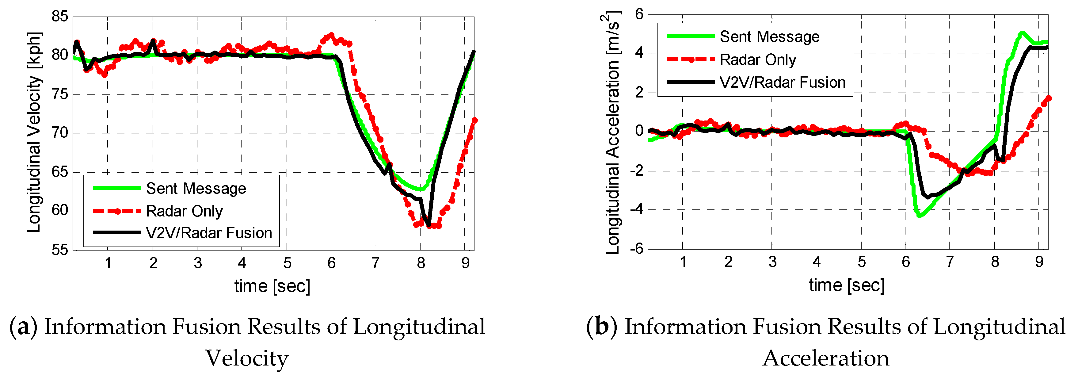
Figure 7 illustrates the remote vehicle state estimation results for the remote vehicle braking scenario on the straight road. The state estimation results in Figure 7 shows that V2V/Radar fusion algorithm outperforms during sudden deceleration of the remote vehicle from 6 s. Since remote vehicle’s accurate vehicle internal sensor signals such as longitudinal velocity and longitudinal acceleration are sent to the host vehicle, the host vehicle does not need to estimate the dynamic behavior of the remote vehicle with certain level of uncertainty and error. Thus, target vehicle tracking performance is significantly improved because of V2V communication compared to radar only situation.

4.2. Active Safety Control

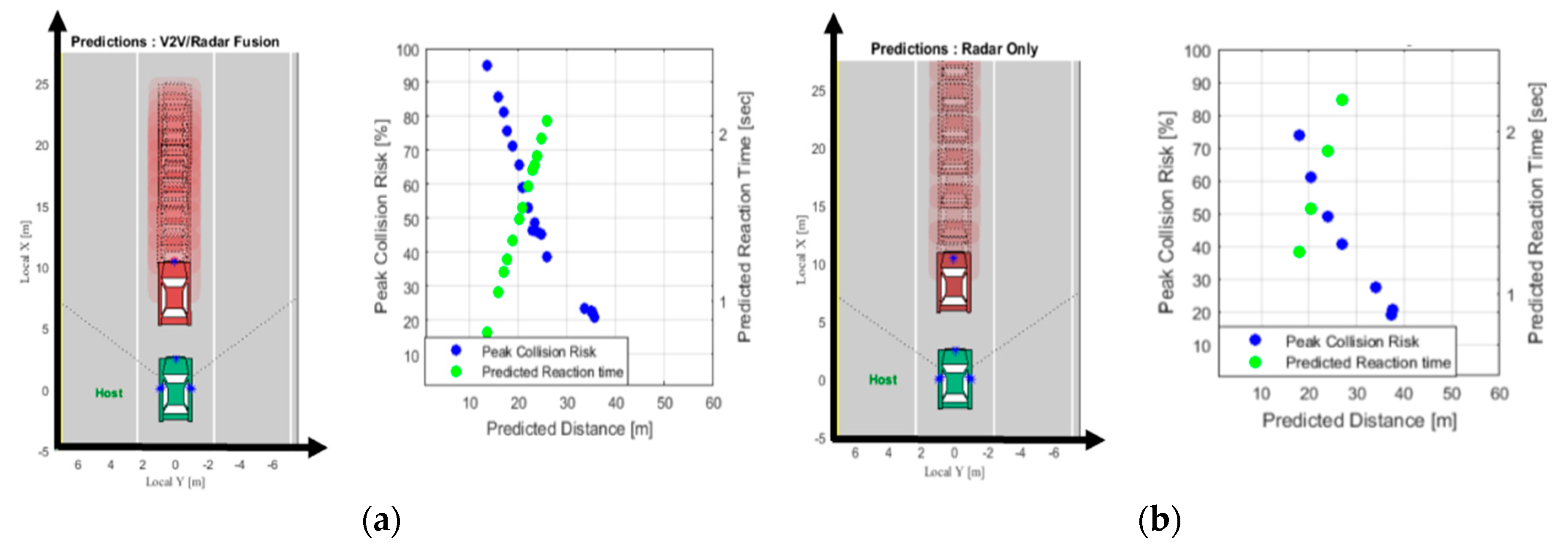
Due to the fact that the V2V communication allows the host vehicle to use more enriched information of the remote vehicle’s state compared to radar only, V2V/Radar fusion algorithm shows more reliable and accurate target detection performance of the remote vehicle when it applies sudden brake as seen in Figure 8b. The simulation results demonstrate the active safety control intervention moment can be detected earlier by 0.5 s because of the V2V communication. The radar only case in Figure 8a has underestimate issue when it compares to V2V/Radar fusion.

4.3. Drive Mode Decision

The human centered risk assessment algorithm works with a probabilistic threat assessment incorporating human factor, and decision of two control functions’ intervention moment. The algorithm computes maxCp (peak collision risk) and DpmaxCp (most probable predicted collision distance) from the preceding threat vehicles.
Figure 9 demonstrates simulation results when the preceding remote vehicle applies the brake on the highway as described in Figure 6b. The host vehicle speed is cruising with the longitudinal velocity of 100 km/h for whole period of simulation. The remote vehicle applies the brake at 4 s for two cases: V2V/Radar fusion and radar only cases. As seen in Figure 9c, the radar only case shows the decision moment of drive mode at 9.2 s. The V2V/Radar fusion case, however, shows earlier timing for drive mode decision of 1.1 s due to the fact that V2V/Radar fusion algorithm has lower prediction uncertainty level than radar only case. This means that the V2V communication has much faster drive mode decision timing by reducing the chances of underestimate of radar only case as seen in Figure 9a,b.
Figure 9 also describe the simulation results for the intervention moment of the active safety function. In the case of V2V/Radar fusion, the collision risk of sudden deceleration of the remote vehicle can be more precisely and reliably computed on the host vehicle as seen in Figure 9c. The active safety intervention moment of V2V/Radar fusion described in Figure 9a is much earlier than that of radar only case in Figure 9b by 0.6 s. For an emergency situation, even 0.1 s is crucial for vehicle crash. Thus, 0.6 s is quite a long amount of time to prevent the collision and give driver more reaction time to stop the vehicle.
Figure 9a,b show the area of safe triangle of V2V/Radar fusion is more enlarged by 13.65% than that of radar only case. This is due to the fact that the distance between two crossing points between the active safety control and the drive mode decision is elongated in the case of V2V/Radar fusion. In other words, V2V communication has much enough time to react hazardous situation by reducing the chances of underestimate risky situation. The safe triangle analysis will be used in the vehicle and it is expected to compute the size of the triangle real time.

5. Conclusions

This paper describes a human-centered risk assessment algorithm with two control functions for automated driving vehicles. The proposed algorithm shows effectiveness of vehicle-to-vehicle communication which significantly improves the safety of automated driving vehicle with faster intervention moment of active safety control and drive mode decision. Since a 5G network-based vehicle-to-vehicle communication overcomes two issues of conventional 4G network-based system; a latency and a package deliver rate (PDR). This provides a host vehicle with more accurate remote vehicle information, and allows predicting the motion of the remote vehicle more accurately. To decide proper intervention moment of active safety control and drive mode, a collision risk and two human reaction times are computed. By incorporating two human factors, the risk assessment system of automated vehicle has been extended to fully automated driving, incorporating human factors. The simulation results show that the proposed algorithm with the V2V communication allows a faster drive mode decision and active safety control for application to automated driving. The effects of V2V communication have been investigated through safe triangle analysis and this shows enlarged area of triangle by 13.65%. This results in proper intervention timing of two control functions with more enough time to react hazardous situation. The proper intervention timing improves driver acceptance since the human-centered algorithm considers human reaction time which reflects the capability of most of the human driver while making drivers understand the situation of the autonomous vehicle better than conventional ADAS. This paper considers full speed range of risk assessment method and drive mode decision with the active safety function is also considered. These two functions are computed with two kinds of reaction time from stopping sight distance and decision sight distance.
In the future, coordination between edge computing and in-vehicle local computing will be implemented and this will be our future research topic. By using 5G-based C-V2X and edge computing, the computation resource is more enriched. In addition, it is expected that real time implementation of particle filter on the test vehicle is possible with the guaranteed performance. For normal driving mode, edge computing-based automated driving is used. When the vehicle encounters emergency situation, the vehicle is controlled by the local computer using vehicle local sensors such as radar and LiDAR and vision. At the same time, vehicle tests will be performed to validate communication performance and the vehicle safety control performance. Communication and sensor information fusion performance is another research topic in the near future

Author Contributions

Conceptualization, D.S. and K.P.; Methodology, D.S.; Software, D.S.; Validation, D.S., K.P. and M.P.; Formal Analysis, K.P.; Investigation, D.S.; Resources, K.P.; Data Curation, D.S.; Writing—Original Draft Preparation, D.S.; Writing—Review and Editing, M.P.; Visualization, D.S.; Supervision, M.P.; Project Administration, D.S.; Funding Acquisition, M.P.

Acknowledgments

This research was supported by the MSIT (Ministry of Science and ICT), Korea, under the ITRC(Information Technology Research Center) support program(IITP-2017-2013-0-00680) supervised by the IITP(Institute for Information &communications Technology Promotion). It was also supported by the 2018 National Research Projects of Naval Research Center, Republic of Korea Naval Academy.

Conflicts of Interest

The authors declare no conflicts of interest.

References

  1. Milanés, V.; Shladover, S.E.; Spring, J.; Nowakowski, C.; Kawazoe, H.; Nakamura, M. Cooperative Adaptive Cruise Control in Real Traffic Situations. IEEE Trans. IEEE Trans. Intell. Transp. Syst. 2014, 15, 296–305. [Google Scholar] [CrossRef] [Green Version]
  2. Karagiannis, G.; Altintas, O.; Ekici, E.; Heijenk, G.; Jarupan, B.; Lin, K.; Weil, T. Vehicular Networking: A Survey and Tutorial on Requirements, Architectures, Challenges, Standards and Solutions. IEEE Commun. Surv. Tutorials 2011, 13, 584–616. [Google Scholar] [CrossRef]
  3. Toyota and Lexus to launch DSRC technology to connect vehicles and infrastructure in the U.S. in 2021. Available online: http://sites.ieee.org/connected-vehicles/2018/04/16/toyota-and-lexus-to-launch-dsrc-technology-to-connect-vehicles-and-infrastructure-in-the-u-s-in-2021/ (accessed on 1 August 2018).
  4. 5GAA, Audi, Ford and Qualcomm Showcase C-V2X Direct Communications Interoperability to Improve Road Safety | Qualcomm. Available online: https://www.qualcomm.com/news/releases/2018/04/26/5gaa-audi-ford-and-qualcomm-showcase-c-v2x-direct-communications (accessed on 1 August 2018).
  5. Shin, D.; Kim, B.; Yi, K.; Carvalho, A.; Borrelli, F. Human-Centered Risk Assessment of an Automated Vehicle Using Vehicular Wireless Communication. IEEE Trans. Intell. Transp. Syst. 2018. [Google Scholar] [CrossRef]
  6. Lv, C.; Xing, Y.; Zhang, J.; Na, X.; Li, Y.; Liu, T.; Cao, D.; Wang, F.-Y. Levenberg–Marquardt Backpropagation Training of Multilayer Neural Networks for State Estimation of a Safety-Critical Cyber-Physical System. IEEE Trans. Ind. Inf. 2018, 14, 3436–3446. [Google Scholar] [CrossRef]
  7. Wan, L.; Raksincharoensak, P.; Maeda, K.; Nagai, M. Lane Change Behavior Modeling for Autonomous Vehicles Based on Surroundings Recognition. Inter. J. Automot. Eng. 2011, 2, 7–12. [Google Scholar]
  8. Tomar, R.S.; Verma, S.; Tomar, G.S. Prediction of Lane Change Trajectories through Neural Network. In Proceedings of the 2010 International Conference on Computational Intelligence and Communication Networks, Bhopal, India, 26–28 November 2010; pp. 249–253. [Google Scholar]
  9. Naranjo, J.E.; Gonzalez, C.; Garcia, R.; De Pedro, T. Lane-Change Fuzzy Control in Autonomous Vehicles for the Overtaking Maneuver. IEEE Trans. Intell. Transp. Syst. 2008, 9, 438. [Google Scholar] [CrossRef]
  10. Layton, R. Decision Sight Distance. The Kiewit Center for Infrastructure and Transportation. 2012. Available online: https://cce.oregonstate.edu/sites/cce.oregonstate.edu/files/12-3-decision-sight-distance.pdf (accessed on 1 August 2018).
  11. Kim, B.; Yi, K.; Yoo, H.-J.; Chong, H.-J.; Ko, B. An IMM/EKF Approach for Enhanced Multitarget State Estimation for Application to Integrated Risk Management System. IEEE Trans. Veh. Technol. 2015, 64, 876–889. [Google Scholar] [CrossRef]
  12. Zingoni, A.; Diani, M.; Corsini, G. A Flexible Algorithm for Detecting Challenging Moving Objects in Real-Time within IR Video Sequences. Remote Sens. 2017, 9, 1128. [Google Scholar] [CrossRef]
  13. Bayless, S.H.; Guan, A.; Son, P.; Murphy, S.; Shaw, A.J. Connected Vehicle Insights: Trends in Roadway Domain Active Sensing: Developments in Radar, LiDAR, and Other Sensing Technologies, and Impact on Vehicle Crash Avoidance/Automation and Active Traffic Management. Available online: https://trid.trb.org/view/1286021 (accessed on 1 August 2018).
  14. Shi, M.; Lu, C.; Zhang, Y.; Yao, D. DSRC and LTE-V Communication Performance Evaluation and Improvement Based on Typical V2X Application at Intersection. In Proceedings of the 2017 Chinese Automation Congress (CAC), Jinan, China, 20–22 October 2017; pp. 556–561. [Google Scholar]
  15. 5G Vision: 100 Billion Connections, 1 ms Latency, and 10 Gbps Throughput. Available online: https://www.huawei.com/minisite/5g/en/defining-5g.html (accessed on 1 August 2018).
  16. De Ponte Müller, F.; Diaz, E.M.; Rashdan, I. Cooperative Positioning and Radar Sensor Fusion for Relative Localization of Vehicles. In Proceedings of the 2016 Intelligent Vehicles Symposium (IV), Gothenburg, Sweden, 19–22 June 2016; pp. 1060–1065. [Google Scholar]
  17. Kloiber, B.; Strang, T.; Röckl, M.; de Ponte Müller, F. Performance of CAM Based Safety Applications Using ITS-G5A MAC in High Dense Scenarios. In Proceedings of the 2011 Intelligent Vehicles Symposium (IV), Baden-Baden, Germany, 5–9 June 2011; pp. 654–660. [Google Scholar]
  18. Takizawa, H.; Yamada, K.; Ito, T. Vehicles Detection Using Sensor Fusion. In Proceedings of the Intelligent Vehicles Symposium, Parma, Italy, 14–17 June 2004; pp. 238–243. [Google Scholar]
  19. Floudas, N.; Polychronopoulos, A.; Aycard, O.; Burlet, J.; Ahrholdt, M. High Level Sensor Data Fusion Approaches for Object Recognition in Road Environment. In Proceedings of the 2007 IEEE Intelligent Vehicles Symposium, Istanbul, Turkey, 13–15 June 2007; pp. 136–141. [Google Scholar]
  20. Jurgen, R.K. V2V/V2I Communications for Improved Road Safety and Efficiency; SAE International: Troy, MC, USA, 2012. [Google Scholar]
  21. Ben-Yaacov, A.; Maltz, M.; Shinar, D. Effects of an In-Vehicle Collision Avoidance Warning System on Short-and Long-Term Driving Performance. Hum. Factors 2002, 44, 335–342. [Google Scholar] [CrossRef] [PubMed]
Figure 1. Range Error vs. Range of Radar and Camera (Vision sensor).
Applsci 08 02632 g001
Figure 2. Experiment results at intersection: (a) Package Deliver Rate (PDR); (b) Latency of DSRC.
Applsci 08 02632 g002
Figure 3. High-Level Information Fusion Architecture.
Applsci 08 02632 g003
Figure 4. Radar measurements (red) need to be associated with the current relative position estimate (blue). The Mahalanobis distance takes also the current estimation uncertainty (blue ellipse) into account.
Applsci 08 02632 g004
Figure 5. Human Centered Risk Assessment-based Safe Triangle Analysis.
Applsci 08 02632 g005
Figure 6. Simulation Scenarios: (a) Parked Remote Vehicle Cut-in and Braking; (b) Remote Vehicle Braking on the Highway.
Applsci 08 02632 g006
Figure 7. Remote vehicle state estimation results: (a) Longitudinal Velocity; (b) Longitudinal Acceleration.
Applsci 08 02632 g007
Figure 8. Simulation results for the braking scenario in Figure 6a: (a) Radar only; (b) V2V/Radar fusion.
Applsci 08 02632 g008
Figure 9. Parameters schematic view of collision probability-based risk assessment: (a) safe triangle analysis: V2V/Radar fusion; (b) safe triangle analysis: Radar only; (c) Peak collision risk of the vehicles: V2V/Radar fusion and Radar only.
Applsci 08 02632 g009
Table 1. Initial setting condition for sensor data acquisition.
Host VehicleRemote Vehicle
Initial Speed30/35/40/45/50/55/60/65/70/75/80 kph20 kph
Initial Range70 m
Table 2. Decision sight distance for a range of speed.
Speed (km/h)Decision Sight Distance for Mode Decision (m)
50170
60205
70235
80270
90315
100355
110380
120415
130450