Study on Elastic Global Shear Buckling of Curved Girders with Corrugated Steel Webs: Theoretical Analysis and FE Modelling

 ,
, 

Abstract
1. Introduction
2. Basic Equations
3. Derivation of the Governing Equations
4. Formulation of the Problem
5. Solution of the Governing Differential Equations
5.1. Displacement Model and the Galerkin Method
5.2. Functional Extremum Value
6. Numerical Study and Comparison
6.1. Element Type and Material Properties
6.2. Geometry and Mesh
6.3. Loading and Boundary Conditions
6.4. Trigonometric Relation between the Dimensions of PCCSW
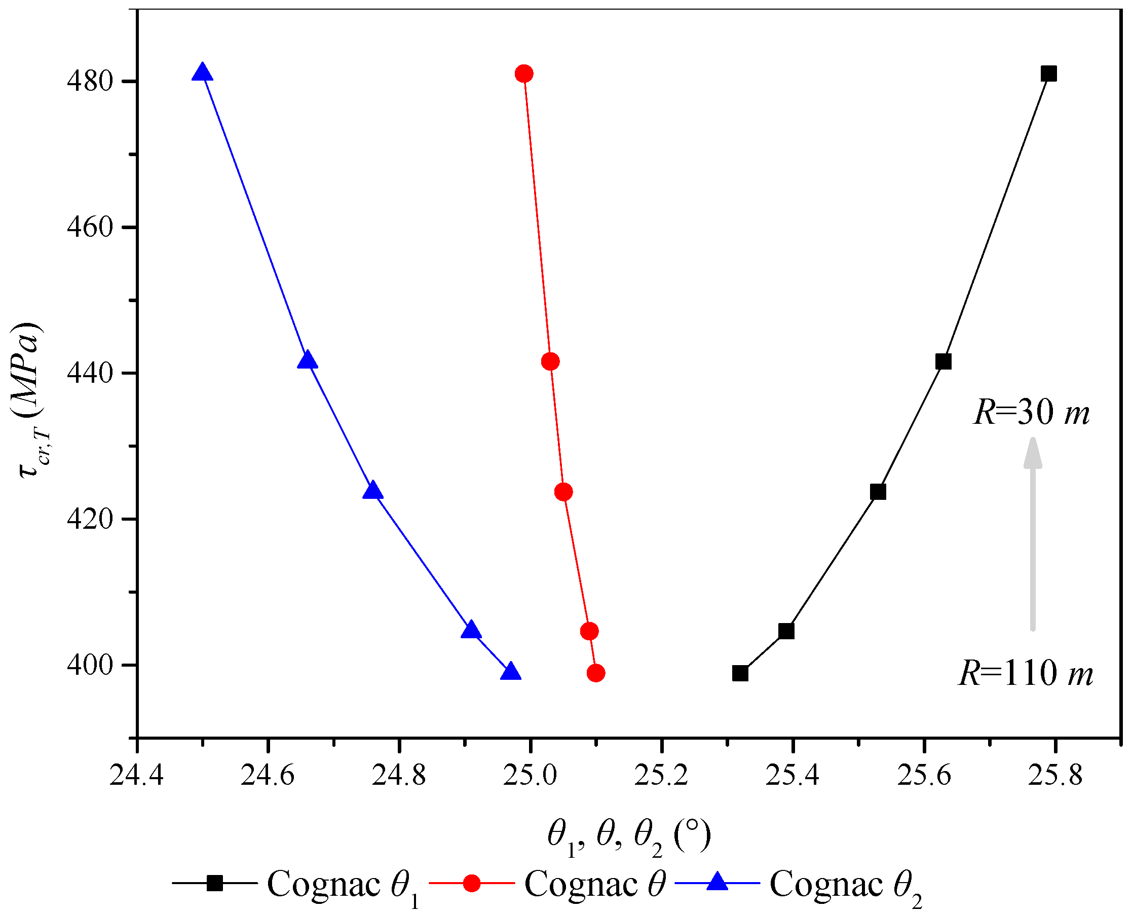
6.5. Angle Relationship of PCCSW
6.6. Parametric Analysis and Comparison
- Corrugation height-to-thickness ratio: hr/t = 8–28;
- Web height-to-thickness ratio: H/t = 136–750;
- Ratio of the bending rigidity in the y-direction to that in the x-direction: Dy/Dx = 139–1483;
- Angle of the inclined panel in relation to the tangent line of the longitudinal axis: θ = 23.62°–39.14°;
- Outer folded angle: θ1 = 23.83°–39.33°;
- Inner folded angle: θ2 = 23.48°–39.02°;
7. Conclusions
- (1)
- According to the elastic theories of shells and orthotropic materials, the governing differential equations of global elastic shear buckling of PCCSW were given. Through a reasonable dis-placement mode, the critical shear stress of the PCCSW of a composite curved girder was obtained by using the Galerkin method and the variational extremum principle.
- (2)
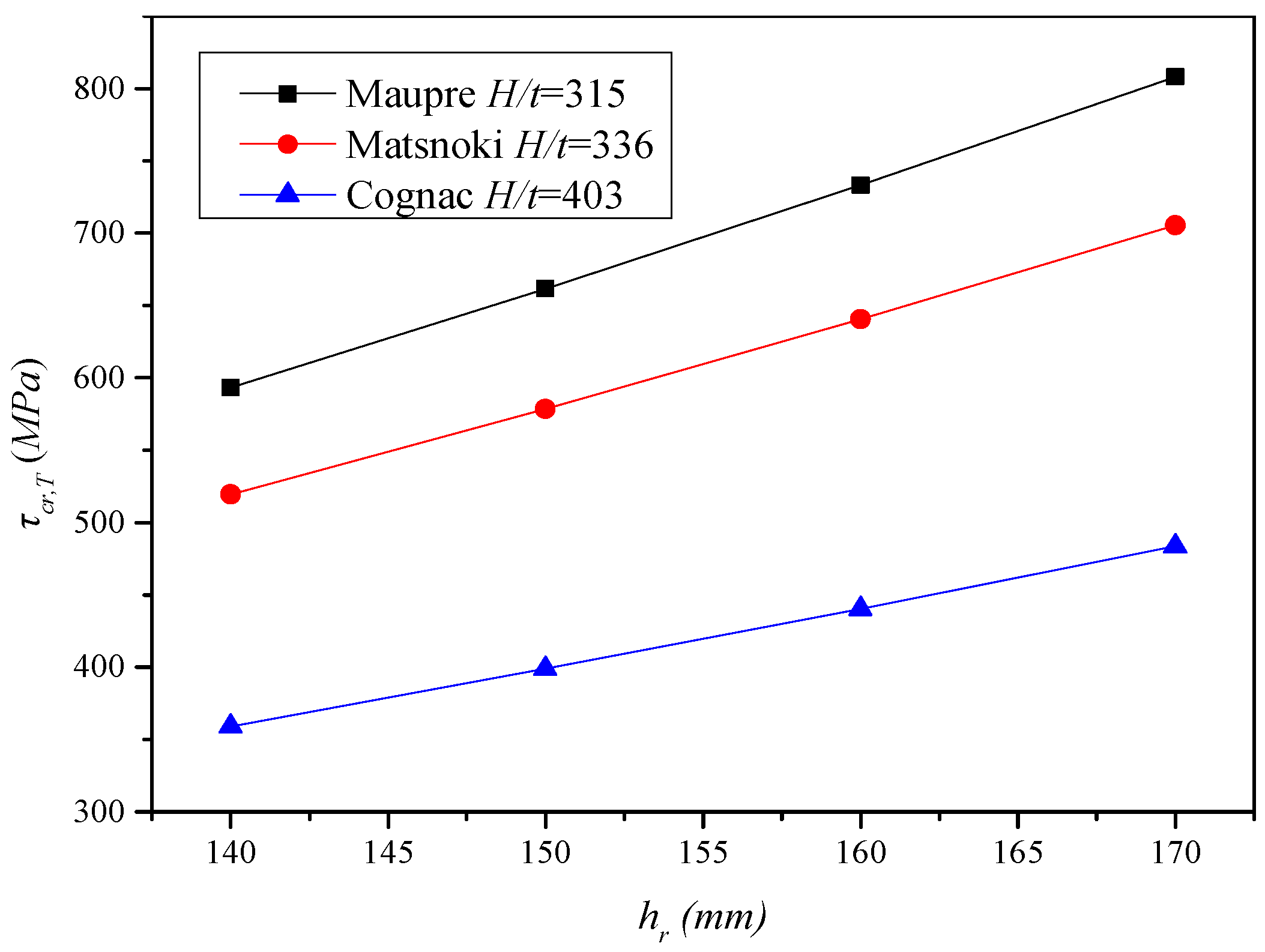
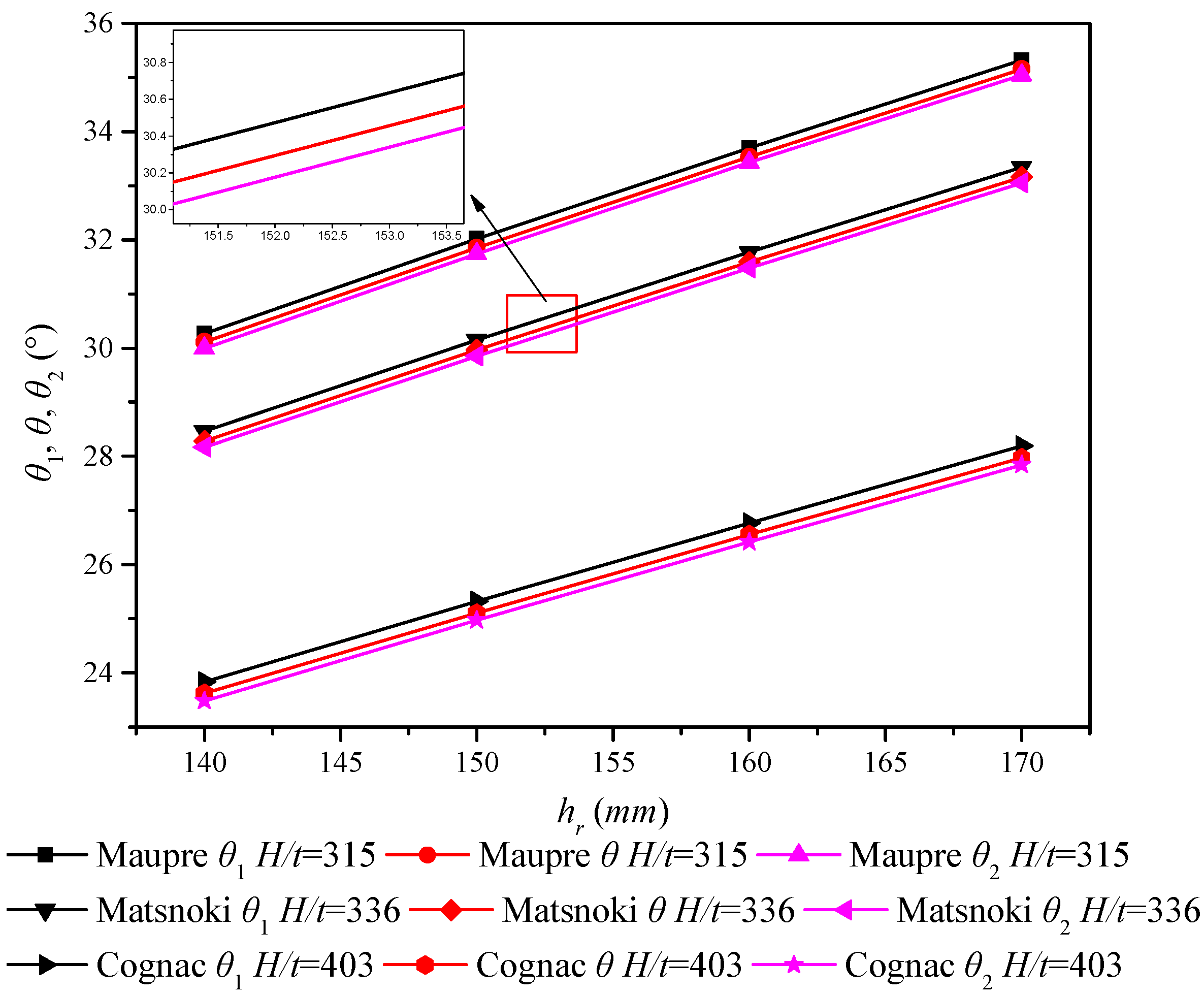
- The correctness of the proposed theoretical buckling formula was verified by the parametric analysis of a series of finite element models. A comparison of the numerical results of the finite element models with theoretical results showed good agreement. It was found that the denser the corrugation of PCCSW with constant curvature radius and height is, the larger the buckling strength is. Additionally, the global shear buckling strength of PCCSW was found to be more sensitive to the variation of the inclined panel width than to that of the longitudinal panel. Moreover, the outer folded angle was found to be greater than the inner folded angle, and the sum of the outer and inner folded angles is slightly larger than two times the intersection angle between the inclined panel and the tangent line of the longitudinal axis. Additionally, the results indicated that the global elastic shear buckling stress of PCCSW increases with a decrease in the curvature radius, especially when R < 60 m. Thus, PCCSW has a stiffening effect on the entire structure under the pure shear condition.
- (3)
- Through analysis of the influence of a constant or variable radius of curvature on buckling performance, the following rules were obtained: when the radius of curvature is constant, the smaller the web height and the ratio of web height-to-thickness are or the greater the web thickness and the corrugation height are, the higher the global elastic shear buckling strength of PCCSW is. However, the global shear buckling critical stress of PCCSW increases with a decrease in the radius of curvature of the PCCSW and its inner angle and an increase in the outer folded angle.
- (4)
- By considering the characteristic of PCCSW, namely, there exist a common effect of geometric curvature and orthotropic properties, the effect of these key factors are considered in the calculation of the global elastic shear buckling of CSWs in a composite curved girder for the first time.
Author Contributions
Funding
Conflicts of Interest
References
- Jiang, R.J.; Kwong, A.F.T.; Xiao, Y.F. Prestressed concrete girder bridges with corrugated steel webs: Review. J. Struct. Eng. 2014, 142, 04014108. [Google Scholar] [CrossRef]
- Hamilton, R.W. Behavior of Welded Girders with Corrugated Webs. Ph.D. Thesis, Department of Civil Engineering, University of Maine, Orono, Maine, 1993. [Google Scholar]
- Sayed-Ahmed, E.Y. Lateral torsion-flexure buckling of corrugated web steel girders. Proc. Inst. Civ. Eng.-Struct. Build. 2005, 158, 53–69. [Google Scholar] [CrossRef]
- Johnson, R.P.; Cafolla, J. Corrugated webs in plate girders for bridges. Proc. Inst. Civ. Eng.-Struct. Build. 1997, 122, 157–164. [Google Scholar] [CrossRef]
- Guo, T.; Sause, R. Analysis of local elastic shear buckling of trapezoidal corrugated steel webs. J. Constr. Steel Res. 2014, 102, 59–71. [Google Scholar] [CrossRef]
- Nguyen, N.D.; Kim, S.N.; Han, S.R. Elastic lateral-torsional buckling strength of I-girder with trapezoidal web corrugations using a new warping constant under uniform moment. Eng. Struct. 2010, 32, 2157–2165. [Google Scholar] [CrossRef]
- Abbas, H.H.; Sause, R.; Driver, R.G. Simplified analysis of flange transverse bending of corrugated web I-girders under in-plane moment and shear. Eng. Struct. 2007, 29, 2816–2824. [Google Scholar] [CrossRef]
- Yi, J.; Gil, H.; Youm, K. Interactive shear buckling behavior of trapezoidally corrugated steel webs. Eng. Struct. 2008, 30, 1659–1666. [Google Scholar] [CrossRef]
- Moon, J.; Yi, J.W.; Choi, B.H. Lateral–torsional buckling of I-girder with corrugated webs under uniform bending. Thin-Walled Struct. 2009, 47, 21–30. [Google Scholar] [CrossRef]
- Kim, K.S.; Lee, D.H. Flexural behavior of prestressed composite beams with corrugated web: Part II. Experiment and verification. Compos. Part B Eng. 2011, 42, 1617–1629. [Google Scholar] [CrossRef]
- Sause, R.; Braxtan, T.N. Shear strength of trapezoidal corrugated steel webs. J. Constr. Steel Res. 2011, 67, 223–236. [Google Scholar] [CrossRef]
- Barakat, S.; Mansouri, A.A.; Altoubat, S. Shear strength of steel beams with trapezoidal corrugated webs using regression analysis. Steel Compos. Struct. 2015, 18, 757–773. [Google Scholar] [CrossRef]
- Easley, J.T. Buckling formulas for corrugated metal shear diaphragms. J. Struct. Div. 1975, 101, 1403–1417. [Google Scholar]
- Galambos, T.V. Guide to Stability Design Criteria for Metal Structures; John Wiley & Sons: Hoboken, NJ, USA, 1998. [Google Scholar]
- Hassanein, M.F.; Kharoob, O.F. Shear buckling behavior of tapered bridge girders with steel corrugated webs. Eng. Struct. 2014, 74, 157–169. [Google Scholar] [CrossRef]
- Hassanein, M.F.; Kharoob, O.F. Linearly tapered bridge girder panels with steel corrugated webs near intermediate supports of continuous bridges. Thin-Walled Struct. 2015, 88, 119–128. [Google Scholar] [CrossRef]
- Zevallos, E.; Hassanein, M.F.; Real, E.; Mirambell, E. Shear evaluation of tapered bridge girder panels with steel corrugated webs near the supports of continuous bridges. Eng. Struct. 2016, 113, 149–159. [Google Scholar] [CrossRef]
- Hassanein, M.F.; Elkawas, A.A.; El Hadidy, A.M.; Elchalakani, M. Shear analysis and design of high-strength steel corrugated web girders for bridge design. Eng. Struct. 2017, 146, 18–33. [Google Scholar] [CrossRef]
- Leblouba, M.; Barakat, S. Shear buckling and stress distribution in trapezoidal web corrugated steel beams. Thin-Walled Struct. 2017, 113, 13–26. [Google Scholar] [CrossRef]
- Zhou, M.; Zhang, J.; Zhong, J.; Zhao, Y. Shear stress calculation and distribution in variable cross sections of box girders with corrugated steel webs. J. Struct. Eng. 2016, 142, 04016022. [Google Scholar] [CrossRef]
- Zhou, M.; Liu, Z.; Zhang, J.; An, L. Deformation analysis of a non-prismatic beam with corrugated steel webs in the elastic stage. Thin-Walled Struct. 2016, 109, 260–270. [Google Scholar] [CrossRef]
- Zhou, M.; Liu, Z.; Zhang, J.; An, L.; He, Z. Equivalent computational models and deflection calculation methods of box girders with corrugated steel webs. Eng. Struct. 2016, 127, 615–634. [Google Scholar] [CrossRef]
- Basher, M.; Shanmugam, N.E.; Khalim, A.R. Horizontally curved composite plate girders with trapezoidally corrugated webs. J. Constr. Steel Res. 2011, 67, 947–956. [Google Scholar] [CrossRef]
- Bedon, C.; Fragiacomo, M. Numerical and analytical assessment of the buckling behaviour of Blockhaus log-walls under in-plane compression. Eng. Struct. 2015, 82, 134–150. [Google Scholar] [CrossRef]
- Bedon, C.; Amadio, C. Buckling analysis and design proposal for 2-side supported double Insulated Glass Units (IGUs) in compression. Eng. Struct. 2018, 168, 23–34. [Google Scholar] [CrossRef]
- Amani, M.; Edlund, B.L.O.; Alinia, M.M. Buckling and postbuckling behavior of unstiffened slender curved plates under uniform shear. Thin-Walled Struct. 2011, 49, 1017–1031. [Google Scholar] [CrossRef]
- Japan Society of Civil Engineers. Design Manual for PC Bridges with Corrugated Steel Webs; Research Committee for Hybrid Structure with Corrugated Steel Webs, Japan Society of Civil Engineers: Tokyo, Japan, 1998. (In Japanese) [Google Scholar]
- Monagan, M.B.; Geddes, K.O.; Heal, K.M. Maple V Programming Guide: For Release 5; Springer Science & Business Media: Waterloo, ON, Canada, 2012. [Google Scholar]
- Timoshenko, S.P.; Gere, J.M. Theory of Elastic Stability, 2nd ed.; McGraw-Hill Book Company: New York, NY, USA, 1963. [Google Scholar]
- ANSYS. ANSYS User’s Manual Revision 12.1; ANSYS, Inc.: Canonsburg, PA, USA, 2012. [Google Scholar]
- Sayed-Ahmed, E.Y. Composite bridges constructed with corrugated steel web box girders. In Proceedings of the International Symposium-Celebrating Concrete: People and Practice, Dundee, UK, 3–4 September 2003; pp. 43–52. [Google Scholar]
- Hassanein, M.F.; Kharoob, O.F. Behavior of Bridge Girders with Corrugated Webs: (I) Real Boundary Conditions at the Juncture of the Web and Flanges. Eng. Struct. 2013, 57, 554–564. [Google Scholar] [CrossRef]
- Lin, W.; Yoda, T. Analysis, design and construction of curved composite girder bridges: State-of-the-art. Int. J. Steel Struct. 2010, 10, 207–220. [Google Scholar] [CrossRef]
- Lei, Z.; Yang, G.; Chen, H. Comparative analysis on main material index of china and international composite girder bridge with corrugated steel web. World Constr. 2016, 5, 11–19. [Google Scholar] [CrossRef]


| PCCSW | OOCCS |
|---|---|
| , | |
| , |
| Boundary | Symbols | AB, CD | AB, CD (Midpoint of Inclined Panel) | AD | BC |
|---|---|---|---|---|---|
| Translation | δx | F | R | R | R |
| δy | F | F | R | F | |
| δz | R | F | R | R | |
| Rotation | θx | F | F | F | F |
| θy | F | F | F | F | |
| θz | F | F | F | F |
| Bridge Name | a (mm) | b (mm) | c (mm) | hr (mm) |
|---|---|---|---|---|
| Shinkai | 250 | 200 | 250 | 150 |
| Maupre | 284 | 241 | 284 | 150 |
| Matsnoki | 300 | 260 | 300 | 150 |
| Hondani | 330 | 270 | 336 | 200 |
| Iisun | 330 | 330 | 386 | 200 |
| Cognac | 353 | 319 | 353 | 150 |
| Dole | 430 | 370 | 430 | 220 |
| Bridge | H (mm) | t (mm) | H/t | hr/t | τcr,T (MPa) | τcr,F (MPa) | τcr,F/τcr,T |
|---|---|---|---|---|---|---|---|
| Shinkai | 2500 | 10 | 250 | 15 | 1067.81 | 914.28 | 0.86 |
| 2500 | 12 | 208 | 13 | 1171.43 | 1157.80 | 0.99 | |
| 2500 | 14 | 179 | 11 | 1267.46 | 1416.00 | 1.12 | |
| 2700 | 10 | 270 | 15 | 916.22 | 887.85 | 0.97 | |
| 2700 | 12 | 225 | 13 | 1005.13 | 1126.23 | 1.12 | |
| 3000 | 8 | 375 | 19 | 664.07 | 635.54 | 0.96 | |
| 3000 | 10 | 300 | 15 | 743.34 | 850.87 | 1.14 | |
| 3500 | 6 | 583 | 25 | 423.83 | 410.31 | 0.97 | |
| Maupre | 2500 | 14 | 179 | 11 | 1242.19 | 1133.89 | 0.91 |
| 2500 | 16 | 156 | 9 | 1330.58 | 1349.98 | 1.01 | |
| 2500 | 18 | 139 | 8 | 1414.45 | 1577.02 | 1.11 | |
| 3150 | 8 | 394 | 19 | 590.98 | 504.48 | 0.85 | |
| 3150 | 10 | 315 | 15 | 661.52 | 674.19 | 1.02 | |
| 3500 | 8 | 438 | 19 | 480.16 | 484.50 | 1.01 | |
| 4000 | 6 | 667 | 25 | 320.08 | 315.94 | 0.99 | |
| Matsnoki | 3000 | 10 | 300 | 15 | 723.65 | 626.20 | 0.87 |
| 3000 | 12 | 250 | 13 | 793.87 | 793.56 | 1.00 | |
| 3000 | 14 | 214 | 11 | 858.94 | 971.79 | 1.13 | |
| 3360 | 8 | 420 | 19 | 516.81 | 450.93 | 0.87 | |
| 3360 | 10 | 336 | 15 | 578.50 | 600.68 | 1.04 | |
| 3500 | 8 | 438 | 19 | 476.94 | 442.29 | 0.93 | |
| 3500 | 10 | 350 | 15 | 533.86 | 592.26 | 1.11 | |
| 4000 | 6 | 667 | 25 | 317.95 | 288.56 | 0.91 | |
| 4000 | 8 | 500 | 19 | 367.48 | 421.28 | 1.15 | |
| Hondani | 3000 | 18 | 167 | 11 | 1535.32 | 1389.96 | 0.91 |
| 3000 | 20 | 150 | 10 | 1620.65 | 1594.30 | 0.98 | |
| 3000 | 22 | 136 | 9 | 1702.39 | 1806.67 | 1.06 | |
| 3600 | 12 | 300 | 17 | 870.10 | 769.07 | 0.88 | |
| 3600 | 14 | 257 | 14 | 940.72 | 939.17 | 1.00 | |
| 3600 | 16 | 225 | 13 | 1006.79 | 1118.26 | 1.11 | |
| 4000 | 10 | 400 | 20 | 644.70 | 582.85 | 0.90 | |
| 4000 | 12 | 333 | 17 | 706.81 | 739.00 | 1.05 | |
| 4500 | 8 | 563 | 25 | 457.60 | 415.81 | 0.91 | |
| 4500 | 10 | 450 | 20 | 511.95 | 557.44 | 1.09 | |
| 5000 | 8 | 625 | 25 | 373.25 | 399.60 | 1.07 | |
| Iisun | 3500 | 16 | 219 | 13 | 1046.32 | 940.38 | 0.90 |
| 3500 | 18 | 194 | 11 | 1111.19 | 1099.46 | 0.99 | |
| 3500 | 20 | 175 | 10 | 1172.94 | 1266.57 | 1.08 | |
| 3960 | 12 | 330 | 17 | 708.64 | 617.80 | 0.87 | |
| 3960 | 14 | 283 | 14 | 766.16 | 757.02 | 0.99 | |
| 3960 | 16 | 248 | 13 | 819.96 | 904.97 | 1.10 | |
| 4500 | 10 | 450 | 20 | 503.29 | 464.78 | 0.92 | |
| 4500 | 12 | 375 | 17 | 551.78 | 591.94 | 1.07 | |
| 5000 | 8 | 625 | 25 | 366.99 | 333.50 | 0.91 | |
| 5000 | 10 | 500 | 20 | 410.58 | 448.70 | 1.09 | |
| 5500 | 8 | 688 | 25 | 306.21 | 322.80 | 1.05 | |
| Cognac | 3500 | 10 | 350 | 15 | 525.70 | 449.89 | 0.86 |
| 3500 | 12 | 292 | 13 | 576.71 | 570.55 | 0.99 | |
| 3500 | 14 | 250 | 11 | 623.98 | 699.18 | 1.12 | |
| 4032 | 8 | 504 | 19 | 356.36 | 319.54 | 0.90 | |
| 4032 | 10 | 403 | 15 | 398.89 | 428.00 | 1.07 | |
| 4500 | 6 | 750 | 25 | 249.74 | 210.50 | 0.84 | |
| 4500 | 8 | 563 | 19 | 288.64 | 307.08 | 1.06 | |
| Dole | 4500 | 14 | 321 | 16 | 682.03 | 608.44 | 0.89 |
| 4500 | 16 | 281 | 14 | 729.79 | 723.76 | 0.99 | |
| 4500 | 18 | 250 | 12 | 774.85 | 844.56 | 1.09 | |
| 4800 | 12 | 400 | 18 | 556.39 | 486.28 | 0.87 | |
| 4800 | 14 | 343 | 16 | 601.45 | 594.08 | 0.99 | |
| 4800 | 16 | 300 | 14 | 643.56 | 707.62 | 1.10 | |
| 5500 | 10 | 550 | 22 | 390.71 | 364.18 | 0.93 | |
| 5500 | 12 | 458 | 18 | 428.28 | 462.27 | 1.08 | |
| 6000 | 8 | 750 | 28 | 296.57 | 263.02 | 0.89 | |
| 6000 | 10 | 600 | 22 | 331.75 | 352.52 | 1.06 | |
| AVE | 1.00 | ||||||
| COV | 0.09 | ||||||
| MAX & MIN values | 1.15 & 0.84 | ||||||
| Bridge | hr (mm) | H (mm) | t (mm) | τcr,T (MPa) | τcr,F (MPa) | τcr,F/τcr,T |
|---|---|---|---|---|---|---|
| Shinkai | 130 | 2700 | 10 | 728.09 | 838.52 | 1.15 |
| 140 | 2700 | 10 | 819.67 | 862.85 | 1.05 | |
| 150 | 2700 | 10 | 916.22 | 887.85 | 0.97 | |
| 160 | 2700 | 10 | 1017.79 | 902.33 | 0.89 | |
| Maupre | 140 | 3150 | 10 | 593.26 | 654.63 | 1.10 |
| 150 | 3150 | 10 | 661.52 | 674.19 | 1.02 | |
| 160 | 3150 | 10 | 733.11 | 691.87 | 0.94 | |
| 170 | 3150 | 10 | 808.05 | 707.62 | 0.88 | |
| Matsnoki | 140 | 3360 | 10 | 519.32 | 582.26 | 1.12 |
| 150 | 3360 | 10 | 578.50 | 600.68 | 1.04 | |
| 160 | 3360 | 10 | 640.49 | 617.59 | 0.96 | |
| 170 | 3360 | 10 | 705.32 | 632.92 | 0.90 | |
| 180 | 3360 | 10 | 772.98 | 646.58 | 0.84 | |
| Hondani | 180 | 3600 | 14 | 794.56 | 905.24 | 1.14 |
| 190 | 3600 | 14 | 866.21 | 923.10 | 1.07 | |
| 200 | 3600 | 14 | 940.72 | 939.17 | 1.00 | |
| 210 | 3600 | 14 | 1018.13 | 953.43 | 0.94 | |
| 220 | 3600 | 14 | 1098.44 | 965.79 | 0.88 | |
| Iisun | 180 | 3960 | 14 | 649.19 | 728.91 | 1.12 |
| 190 | 3960 | 14 | 706.58 | 743.58 | 1.05 | |
| 200 | 3960 | 14 | 766.16 | 757.02 | 0.99 | |
| 210 | 3960 | 14 | 827.93 | 769.17 | 0.93 | |
| 220 | 3960 | 14 | 891.91 | 780.10 | 0.87 | |
| Cognac | 140 | 4032 | 10 | 359.16 | 413.22 | 1.15 |
| 150 | 4032 | 10 | 398.89 | 428.00 | 1.07 | |
| 160 | 4032 | 10 | 440.41 | 441.96 | 1.00 | |
| 170 | 4032 | 10 | 483.69 | 455.03 | 0.94 | |
| 180 | 4032 | 10 | 528.75 | 467.24 | 0.88 | |
| Dole | 200 | 4800 | 14 | 518.84 | 569.09 | 1.10 |
| 210 | 4800 | 14 | 559.46 | 581.95 | 1.04 | |
| 220 | 4800 | 14 | 601.45 | 594.08 | 0.99 | |
| 230 | 4800 | 14 | 644.81 | 605.46 | 0.94 | |
| 240 | 4800 | 14 | 689.55 | 616.09 | 0.89 | |
| AVE | 1.00 | |||||
| COV | 0.09 |
| Bridge | θ (°) | θ1 (°) | θ2 (°) | H (mm) | t (mm) | hr (mm) | τcr,T (MPa) |
|---|---|---|---|---|---|---|---|
| Shinkai | 33.00 | 33.14 | 32.91 | 2700 | 10 | 130 | 728.09 |
| 34.97 | 35.11 | 34.87 | 2700 | 10 | 140 | 819.67 | |
| 36.84 | 36.99 | 36.75 | 2700 | 10 | 150 | 916.22 | |
| 38.63 | 38.78 | 38.54 | 2700 | 10 | 160 | 1017.79 | |
| Maupre | 30.11 | 30.27 | 30.00 | 3150 | 10 | 140 | 593.26 |
| 31.85 | 32.02 | 31.74 | 3150 | 10 | 150 | 661.52 | |
| 33.53 | 33.70 | 33.43 | 3150 | 10 | 160 | 733.11 | |
| 35.15 | 35.32 | 35.04 | 3150 | 10 | 170 | 808.05 | |
| Matsnoki | 28.28 | 28.46 | 28.17 | 3360 | 10 | 140 | 519.32 |
| 29.97 | 30.15 | 29.85 | 3360 | 10 | 150 | 578.50 | |
| 31.59 | 31.77 | 31.48 | 3360 | 10 | 160 | 640.49 | |
| 33.16 | 33.34 | 33.05 | 3360 | 10 | 170 | 705.32 | |
| 34.68 | 34.86 | 34.57 | 3360 | 10 | 180 | 772.98 | |
| Hondani | 33.66 | 33.85 | 33.53 | 3600 | 14 | 180 | 794.56 |
| 35.10 | 35.29 | 34.98 | 3600 | 14 | 190 | 866.21 | |
| 36.49 | 36.69 | 36.37 | 3600 | 14 | 200 | 940.72 | |
| 37.84 | 38.03 | 37.72 | 3600 | 14 | 210 | 1018.13 | |
| 39.14 | 39.33 | 39.02 | 3600 | 14 | 220 | 1098.44 | |
| Iisun | 28.56 | 28.77 | 28.43 | 3960 | 14 | 180 | 649.19 |
| 29.88 | 30.09 | 29.75 | 3960 | 14 | 190 | 706.58 | |
| 31.16 | 31.38 | 31.04 | 3960 | 14 | 200 | 766.16 | |
| 32.42 | 32.63 | 32.29 | 3960 | 14 | 210 | 827.93 | |
| 33.64 | 33.85 | 33.51 | 3960 | 14 | 220 | 891.91 | |
| Cognac | 23.62 | 23.83 | 23.48 | 4032 | 10 | 140 | 359.16 |
| 25.10 | 25.32 | 24.97 | 4032 | 10 | 150 | 398.89 | |
| 26.56 | 26.77 | 26.42 | 4032 | 10 | 160 | 440.41 | |
| 27.97 | 28.19 | 27.84 | 4032 | 10 | 170 | 483.69 | |
| 29.35 | 29.57 | 29.22 | 4032 | 10 | 180 | 528.75 | |
| Dole | 28.38 | 28.64 | 28.22 | 4800 | 14 | 200 | 518.84 |
| 29.57 | 29.82 | 29.41 | 4800 | 14 | 210 | 559.46 | |
| 30.72 | 30.98 | 30.56 | 4800 | 14 | 220 | 601.45 | |
| 31.86 | 32.11 | 31.70 | 4800 | 14 | 230 | 644.81 | |
| 32.96 | 33.22 | 32.80 | 4800 | 14 | 240 | 689.55 |
| Bridge | R (m) | H (mm) | t (mm) | τcr,T (MPa) | τcr,F (MPa) | τcr,F/τcr,T |
|---|---|---|---|---|---|---|
| Shinkai | ∞ | 2700 | 10 | 913.40 | 884.19 | 0.97 |
| 110 | 2700 | 10 | 916.22 | 887.85 | 0.97 | |
| 80 | 2700 | 10 | 918.74 | 887.89 | 0.97 | |
| 50 | 2700 | 10 | 927.08 | 889.85 | 0.96 | |
| 40 | 2700 | 10 | 934.79 | 892.89 | 0.96 | |
| 30 | 2700 | 10 | 951.53 | 897.89 | 0.94 | |
| Maupre | ∞ | 3150 | 10 | 657.65 | 673.24 | 1.02 |
| 110 | 3150 | 10 | 661.52 | 674.19 | 1.02 | |
| 80 | 3150 | 10 | 664.97 | 675.21 | 1.02 | |
| 50 | 3150 | 10 | 676.43 | 677.08 | 1.00 | |
| 40 | 3150 | 10 | 687.06 | 678.70 | 0.99 | |
| 30 | 3150 | 10 | 710.19 | 681.11 | 0.96 | |
| Matsnoki | ∞ | 3360 | 10 | 574.09 | 599.82 | 1.04 |
| 110 | 3360 | 10 | 578.50 | 600.68 | 1.04 | |
| 80 | 3360 | 10 | 582.43 | 601.58 | 1.03 | |
| 50 | 3360 | 10 | 595.52 | 602.26 | 1.01 | |
| 40 | 3360 | 10 | 607.69 | 603.27 | 0.99 | |
| 30 | 3360 | 10 | 634.22 | 604.76 | 0.95 | |
| Hondani | ∞ | 3600 | 14 | 935.58 | 937.84 | 1.00 |
| 110 | 3600 | 14 | 940.72 | 939.17 | 1.00 | |
| 80 | 3600 | 14 | 945.31 | 939.76 | 0.99 | |
| 50 | 3600 | 14 | 960.54 | 940.54 | 0.98 | |
| 40 | 3600 | 14 | 974.66 | 941.63 | 0.97 | |
| 30 | 3600 | 14 | 1005.39 | 943.23 | 0.94 | |
| Iisun | ∞ | 3960 | 14 | 759.90 | 755.99 | 0.99 |
| 110 | 3960 | 14 | 766.16 | 757.02 | 0.99 | |
| 80 | 3960 | 14 | 771.74 | 757.43 | 0.98 | |
| 50 | 3960 | 14 | 790.33 | 757.95 | 0.96 | |
| 40 | 3960 | 14 | 807.60 | 758.77 | 0.94 | |
| 30 | 3960 | 14 | 845.31 | 759.94 | 0.90 | |
| Cognac | ∞ | 4032 | 10 | 392.50 | 427.38 | 1.09 |
| 110 | 4032 | 10 | 398.89 | 428.00 | 1.07 | |
| 80 | 4032 | 10 | 404.61 | 428.27 | 1.06 | |
| 50 | 4032 | 10 | 423.72 | 428.65 | 1.01 | |
| 40 | 4032 | 10 | 441.60 | 429.14 | 0.97 | |
| 30 | 4032 | 10 | 481.01 | 429.86 | 0.89 | |
| Dole | ∞ | 4800 | 14 | 592.65 | 593.24 | 1.00 |
| 110 | 4800 | 14 | 601.45 | 594.08 | 0.99 | |
| 80 | 4800 | 14 | 609.31 | 594.46 | 0.98 | |
| 50 | 4800 | 14 | 635.58 | 594.97 | 0.94 | |
| 40 | 4800 | 14 | 660.12 | 595.67 | 0.90 | |
| 30 | 4800 | 14 | 714.13 | 599.96 | 0.84 | |
| AVE | 0.98 | |||||
| COV | 0.05 |
| Bridge | θ (°) | θ1 (°) | θ2 (°) | H (mm) | t (mm) | R (m) | τcr,T (MPa) |
|---|---|---|---|---|---|---|---|
| Shinkai | 36.84 | 36.99 | 36.75 | 2700 | 10 | 110 | 916.22 |
| 36.83 | 37.03 | 36.71 | 2700 | 10 | 80 | 918.74 | |
| 36.81 | 37.13 | 36.61 | 2700 | 10 | 50 | 927.08 | |
| 36.80 | 37.19 | 36.55 | 2700 | 10 | 40 | 934.79 | |
| 36.77 | 37.30 | 36.44 | 2700 | 10 | 30 | 951.53 | |
| Maupre | 31.85 | 32.02 | 31.74 | 3150 | 10 | 110 | 661.52 |
| 31.84 | 32.07 | 31.69 | 3150 | 10 | 80 | 664.97 | |
| 31.81 | 32.18 | 31.58 | 3150 | 10 | 50 | 676.43 | |
| 31.80 | 32.26 | 31.51 | 3150 | 10 | 40 | 687.06 | |
| 31.77 | 32.38 | 31.38 | 3150 | 10 | 30 | 710.19 | |
| Matsnoki | 29.97 | 30.15 | 29.85 | 3360 | 10 | 110 | 578.50 |
| 29.95 | 30.20 | 29.80 | 3360 | 10 | 80 | 582.43 | |
| 29.93 | 30.32 | 29.68 | 3360 | 10 | 50 | 595.52 | |
| 29.91 | 30.40 | 29.60 | 3360 | 10 | 40 | 607.69 | |
| 29.88 | 30.53 | 29.46 | 3360 | 10 | 30 | 634.22 | |
| Hondani | 36.49 | 36.69 | 36.37 | 3600 | 14 | 110 | 940.72 |
| 36.48 | 36.74 | 36.31 | 3600 | 14 | 80 | 945.31 | |
| 36.45 | 36.87 | 36.19 | 3600 | 14 | 50 | 960.54 | |
| 36.43 | 36.96 | 36.10 | 3600 | 14 | 40 | 974.66 | |
| 36.40 | 37.10 | 35.96 | 3600 | 14 | 30 | 1005.39 | |
| Iisun | 31.16 | 31.38 | 31.04 | 3960 | 14 | 110 | 766.16 |
| 31.15 | 31.44 | 30.97 | 3960 | 14 | 80 | 771.74 | |
| 31.11 | 31.58 | 30.83 | 3960 | 14 | 50 | 790.33 | |
| 31.09 | 31.68 | 30.73 | 3960 | 14 | 40 | 807.60 | |
| 31.05 | 31.84 | 30.58 | 3960 | 14 | 30 | 845.31 | |
| Cognac | 25.10 | 25.32 | 24.97 | 4032 | 10 | 110 | 398.89 |
| 25.09 | 25.39 | 24.91 | 4032 | 10 | 80 | 404.61 | |
| 25.05 | 25.53 | 24.76 | 4032 | 10 | 50 | 423.72 | |
| 25.03 | 25.63 | 24.66 | 4032 | 10 | 40 | 441.60 | |
| 24.99 | 25.79 | 24.50 | 4032 | 10 | 30 | 481.01 | |
| Dole | 30.72 | 30.98 | 30.56 | 4800 | 14 | 110 | 601.45 |
| 30.71 | 31.06 | 30.49 | 4800 | 14 | 80 | 609.31 | |
| 30.67 | 31.23 | 30.31 | 4800 | 14 | 50 | 635.58 | |
| 30.64 | 31.34 | 30.20 | 4800 | 14 | 40 | 660.12 | |
| 30.60 | 31.53 | 30.01 | 4800 | 14 | 30 | 714.13 |
© 2018 by the authors. Licensee MDPI, Basel, Switzerland. This article is an open access article distributed under the terms and conditions of the Creative Commons Attribution (CC BY) license (http://creativecommons.org/licenses/by/4.0/).
Share and Cite
Wang, K.; Zhou, M.; Hassanein, M.F.; Zhong, J.; Ding, H.; An, L. Study on Elastic Global Shear Buckling of Curved Girders with Corrugated Steel Webs: Theoretical Analysis and FE Modelling. Appl. Sci. 2018, 8, 2457. https://doi.org/10.3390/app8122457
Wang K, Zhou M, Hassanein MF, Zhong J, Ding H, An L. Study on Elastic Global Shear Buckling of Curved Girders with Corrugated Steel Webs: Theoretical Analysis and FE Modelling. Applied Sciences. 2018; 8(12):2457. https://doi.org/10.3390/app8122457
Chicago/Turabian StyleWang, Kangjian, Man Zhou, Mostafa Fahmi Hassanein, Jitao Zhong, Hanshan Ding, and Lin An. 2018. "Study on Elastic Global Shear Buckling of Curved Girders with Corrugated Steel Webs: Theoretical Analysis and FE Modelling" Applied Sciences 8, no. 12: 2457. https://doi.org/10.3390/app8122457
APA StyleWang, K., Zhou, M., Hassanein, M. F., Zhong, J., Ding, H., & An, L. (2018). Study on Elastic Global Shear Buckling of Curved Girders with Corrugated Steel Webs: Theoretical Analysis and FE Modelling. Applied Sciences, 8(12), 2457. https://doi.org/10.3390/app8122457