Evaluation of Effective Elastic Properties of Nitride NWs/Polymer Composite Materials Using Laser-Generated Surface Acoustic Waves

 , ,
, ,  , ,
, , 
Abstract
1. Introduction
2. Materials and Experimental Set-Up
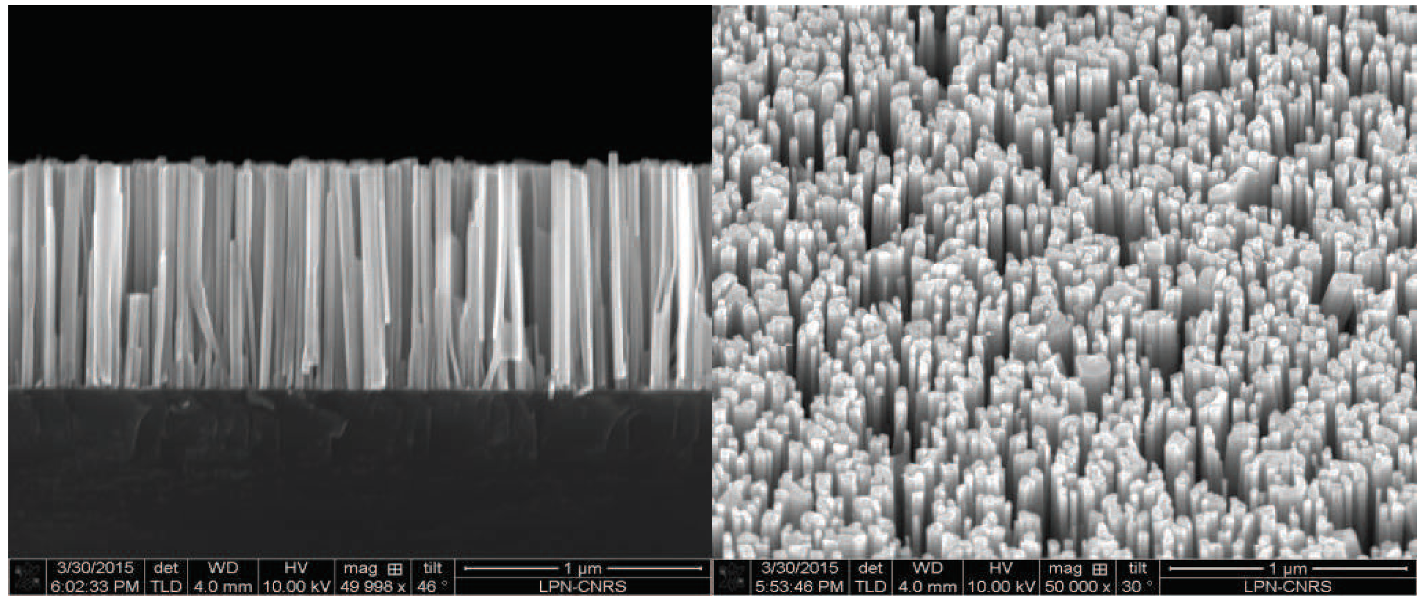
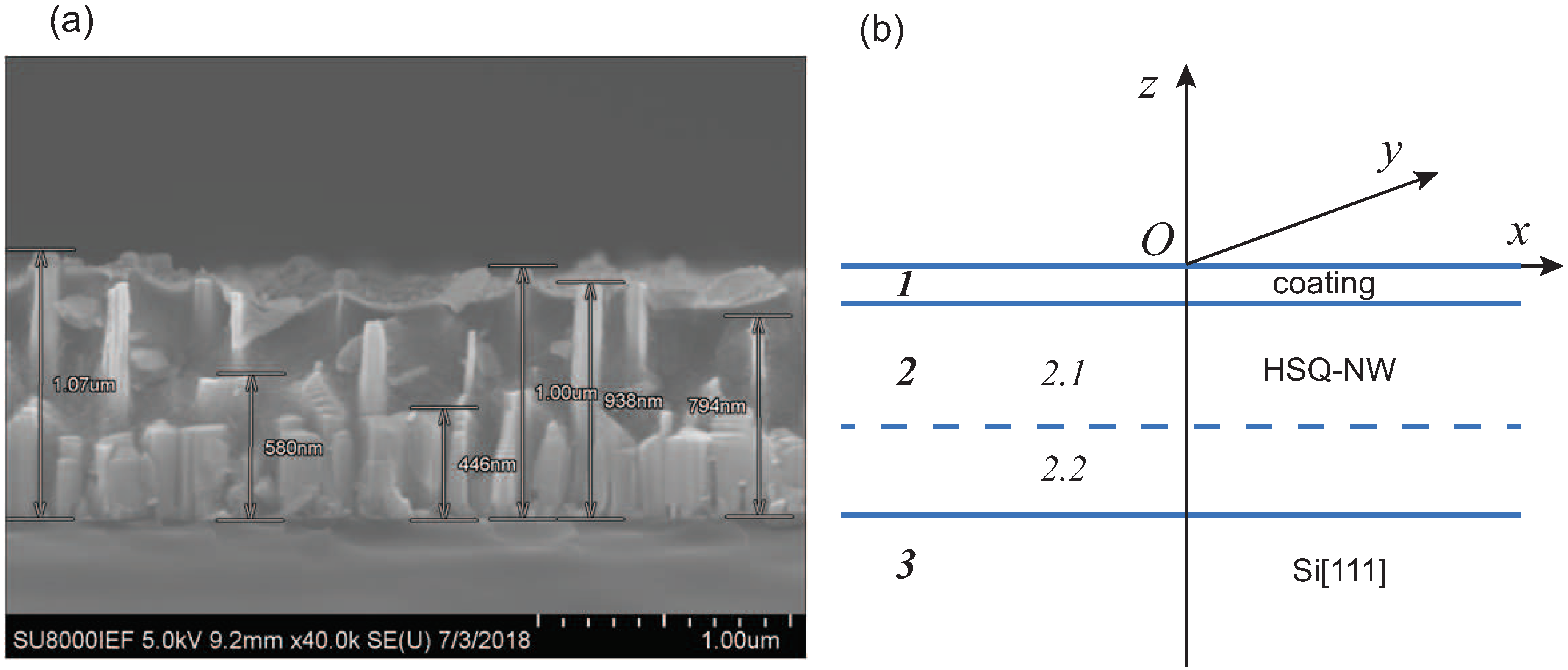
2.1. Samples
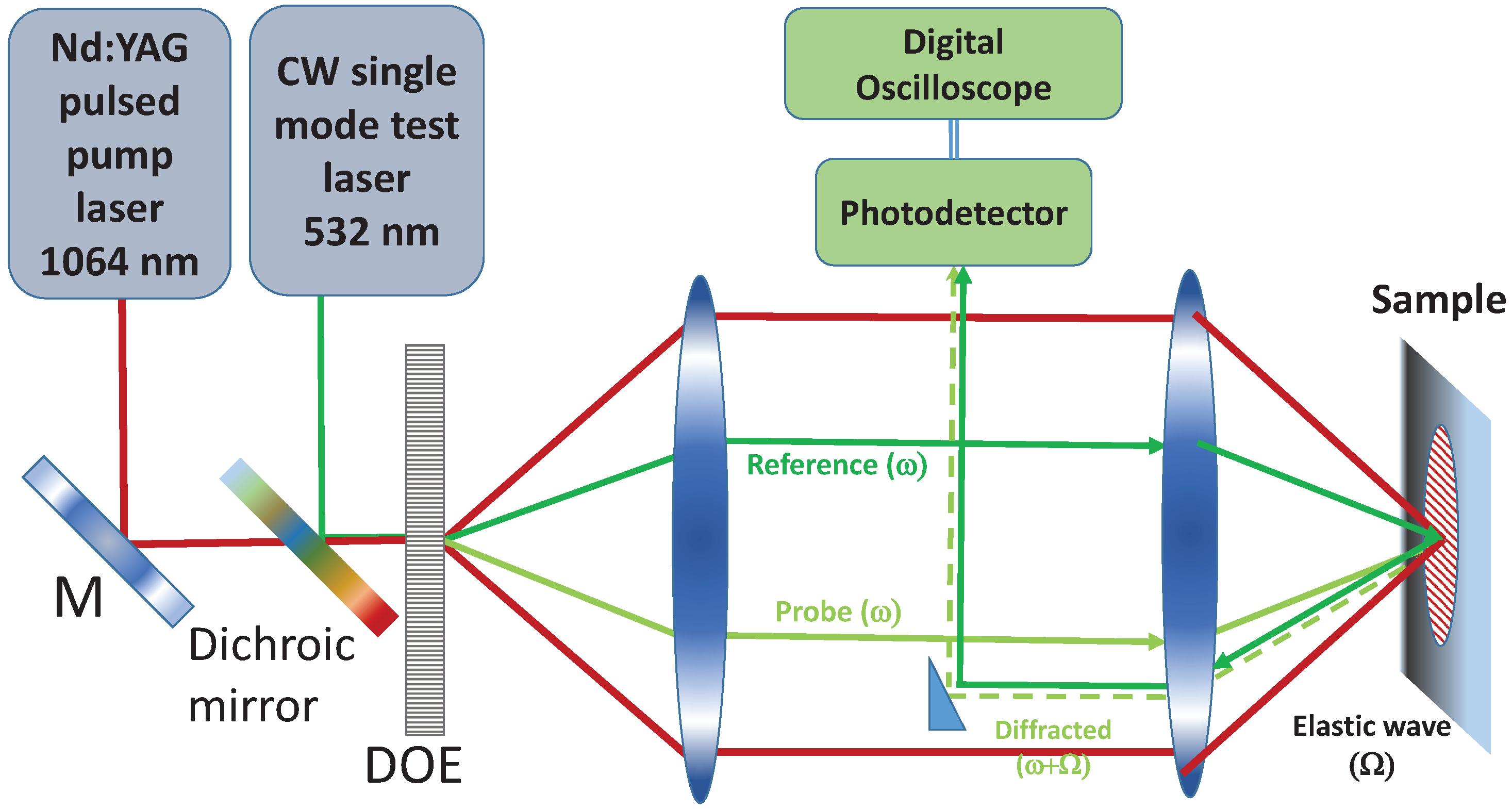
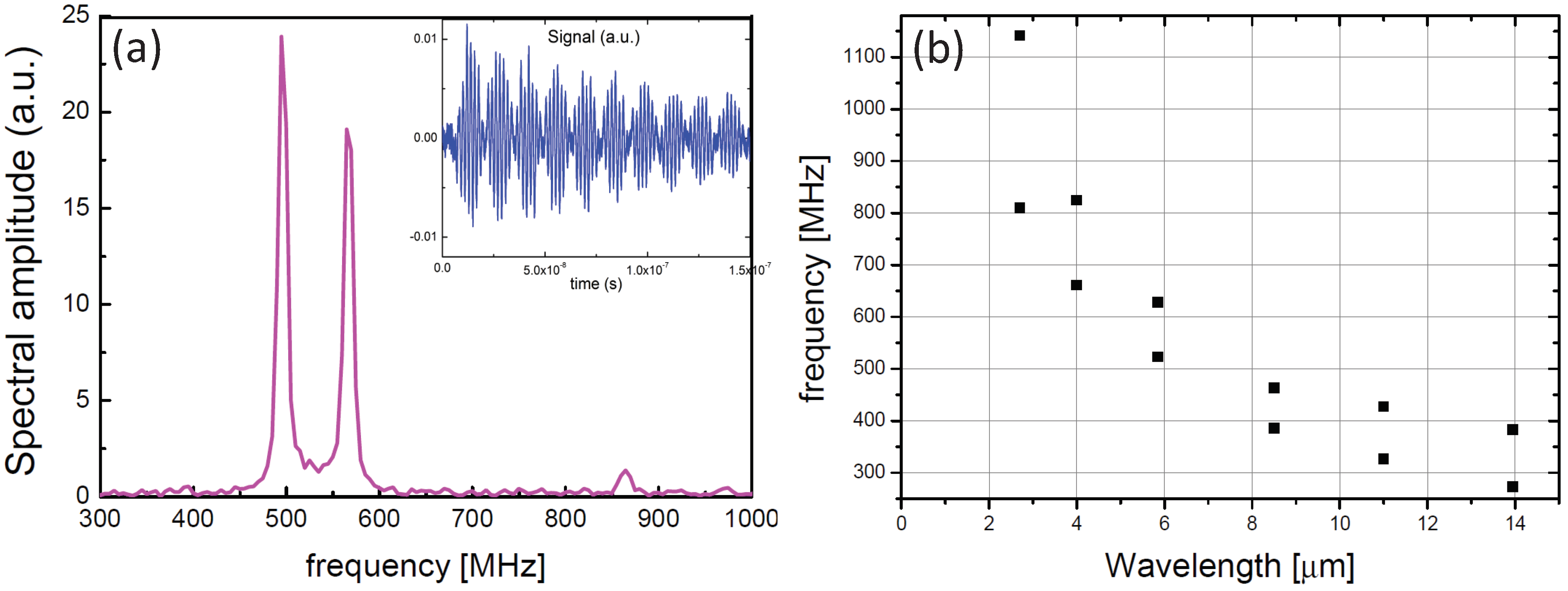
2.2. Experimental Technique
3. Theoretical Framework
3.1. Premises
3.2. Simulation
3.3. Validation
3.4. Inverse Problem
4. Results and Discussion
4.1. Meaning of Effective Parameters
4.2. High Density Straight NWs and Rare NWs with Thick 2D-Layer
4.3. Effect of Number of Sublayers
4.4. Influence of Annealing Temperature
5. Conclusions
Author Contributions
Funding
Acknowledgments
Conflicts of Interest
References
- Schimpke, T.; Mandl, M.; Stoll, I.; Pohl-Klein, B.; Bichler, D.; Zwaschka, F.; Strube-Knyrim, J.; Huckenbeck, B.; Max, B.; Müller, M.; et al. Phosphor-converted white light from blue-emitting InGaN microrod LEDs. Phys. Status Solidi (A) 2016, 213, 1577–1584. [Google Scholar] [CrossRef]
- Soci, C.; Zhang, A.; Xiang, B.; Dayeh, S.A.; Aplin, D.P.R.; Park, J.; Bao, X.Y.; Lo, Y.H.; Wang, D. ZnO nanowire UV photodetectors with high internal gain. Nano Lett. 2007, 7, 1003–1009. [Google Scholar] [CrossRef] [PubMed]
- Xu, S.; Hansen, B.J.; Wang, Z.L. Piezoelectric-nanowire-enabled power source for driving wireless microelectronics. Nat. Commun. 2010, 1, 93. [Google Scholar] [CrossRef] [PubMed]
- Ahmad, R.; Mahmoudi, T.; Ahn, M.S.; Hahn, Y.B. Recent advances in nanowires-based field-effect transistors for biological sensor applications. Biosens. Bioelectron. 2018, 100, 312–325. [Google Scholar] [CrossRef] [PubMed]
- Jamond, N.; Chrétien, P.; Houzé, F.; Lu, L.; Largeau, L.; Maugain, O.; Travers, L.; Harmand, J.C.; Glas, F.; Lefeuvre, E.; Tchernycheva, M.; Gogneau, N. Piezo-generator integrating a vertical array of GaN nanowires. Nanotechnology 2016, 27, 325403. [Google Scholar] [CrossRef] [PubMed]
- Mante, P.A.; Lehmann, S.; Anttu, N.; Dick, K.A.; Yartsev, A. Nondestructive complete mechanical characterization of zinc blende and wurtzite GaAs nanowires using time-resolved pump–probe spectroscopy. Nano Lett. 2016, 16, 4792–4798. [Google Scholar] [CrossRef] [PubMed]
- Nam, C.Y.; Jaroenapibal, P.; Tham, D.; Luzzi, D.E.; Evoy, S.; Fischer, J.E. Diameter-dependent electromechanical properties of GaN nanowires. Nano Lett. 2006, 6, 153–158. [Google Scholar] [CrossRef] [PubMed]
- Wang, Z.L.; Song, J. Piezoelectric nanogenerators based on zinc oxide nanowire arrays. Science 2006, 312, 242–246. [Google Scholar] [CrossRef] [PubMed]
- Gogneau, N.; Chretien, P.; Galopin, E.; Guilet, S.; Travers, L.; Harmand, J.; Houze, F. GaN nanowires for piezoelectric generators. Phys. Status Solidi 2014, 8, 414–419. [Google Scholar] [CrossRef]
- Gulans, A.; Tale, I. Ab initio calculation of wurtzite-type GaN nanowires. Phys. Status Solidi (C) 2007, 4, 1197–1200. [Google Scholar] [CrossRef]
- Brown, J.; Baca, A.; Bertness, K.; Dikin, D.; Ruoff, R.; Bright, V. Tensile measurement of single crystal gallium nitride nanowires on MEMS test stages. Sens. Actuators A Phys. 2011, 166, 177–186. [Google Scholar] [CrossRef]
- Bernal, R.A.; Agrawal, R.; Peng, B.; Bertness, K.A.; Sanford, N.A.; Davydov, A.V.; Espinosa, H.D. Effect of growth orientation and diameter on the elasticity of GaN nanowires. A combined in situ TEM and atomistic modeling investigation. Nano Lett. 2011, 11, 548–555. [Google Scholar] [CrossRef] [PubMed]
- Dhar, L.; Rogers, J.A. High frequency one-dimensional phononic crystal characterized with a picosecond transient grating photoacoustic technique. Appl. Phys. Lett. 2000, 77, 1402–1404. [Google Scholar] [CrossRef]
- Maznev, A.A. Band gaps and Brekhovskikh attenuation of laser-generated surface acoustic waves in a patterned thin film structure on silicon. Phys. Rev. B 2008, 78, 155323. [Google Scholar] [CrossRef]
- Taschin, A.; Bartolini, P.; Ricci, M.; Torre, R. Transient grating experiment on supercooled water. Philos. Mag. 2004, 84, 1471–1479. [Google Scholar] [CrossRef]
- Glushkov, E.; Glushkova, N.; Eremin, A. Forced wave propagation and energy distribution in anisotropic laminate composites. J. Acoust. Soc. Am. 2011, 129, 2923–2934. [Google Scholar] [CrossRef] [PubMed]
- Glushkov, E.; Glushkova, N.; Zhang, C. Surface and pseudo-surface acoustic waves piezoelectrically excited in diamond-based structures. J. Appl. Phys. 2012, 112, 064911. [Google Scholar] [CrossRef]
- Largeau, L.; Galopin, E.; Gogneau, N.; Travers, L.; Glas, F.; Harmand, J.C. N-polar GaN nanowires seeded by Al droplets on Si(111). Cryst. Growth Des. 2012, 12, 2724–2729. [Google Scholar] [CrossRef]
- Largeau, L.; Dheeraj, D.L.; Tchernycheva, M.; Cirlin, G.E.; Harmand, J.C. Facet and in-plane crystallographic orientations of GaN nanowires grown on Si(111). Nanotechnology 2008, 19, 155704. [Google Scholar] [CrossRef] [PubMed]
- Glushkov, Y.V.; Glushkova, N.V.; Krivonos, A. The excitation and propagation of elastic waves in multilayered anisotropic composites. J. Appl. Math. Mech. 2010, 74, 297–305. [Google Scholar] [CrossRef]
- Krishnakumar, K. Micro-genetic algorithms for stationary and non-stationary function optimization. Proc. SPIE 1990, 1196, 289–297. [Google Scholar] [CrossRef]
- Eremin, A.A.; Glushkov, Y.V.; Glushkova, N.V.; Lammering, R. Evaluation of effective elastic properties of layered composite fiber-reinforced plastic plates by piezoelectrically induced guided waves and laser Doppler vibrometry. Compos. Struct. 2015, 125, 449–458. [Google Scholar] [CrossRef]
- Bochud, N.; Laurent, J.; Bruno, F.; Royer, D.; Prada, C. Towards real-time assessment of anisotropic plate properties using elastic guided waves. J. Acoust. Soc. Am. 2018, 143, 1138–1147. [Google Scholar] [CrossRef] [PubMed]
- Cook, R.F. Mechanical properties of low dielectric-constant organic-inorganic Hybrids. MRS Proc. 1999, 576, 301–312. [Google Scholar] [CrossRef]


| CrPt | 315 | 315 | 193 | 61 | 61 | 21.5 | |||||
| Si[111] | 195 | 205 | 175 | 189 |
| h | ||||||||||||
|---|---|---|---|---|---|---|---|---|---|---|---|---|
| sample Figure 1 | 129 | 1059 | 128 | |||||||||
| sample Figure 2 | 106 | 887 | 106 |
| h | ||||||||||||
|---|---|---|---|---|---|---|---|---|---|---|---|---|
| CrPt | ||||||||||||
| 349 | 349 | 210 | 70 | 70 | 20 | 80 | 3.21 | 47.0 | 8.14 | 0.48 | 0.24 | |
| 344 | 344 | 222 | 61 | 61 | 19 | 144 | ||||||
| HSQ-NW400 | ||||||||||||
| 1001 | 3.21 | 47.0 | 8.14 | 0.48 | 0.24 | |||||||
| 314 | 45.4 | 79.5 | 2.92 | 0.30 | 0.10 | |||||||
| 363 | 528 | 363 |
| h | ||||||||||||
|---|---|---|---|---|---|---|---|---|---|---|---|---|
| °C | ||||||||||||
| CrPt | 490 | 490 | 366 | 150 | 176 | 176 | 61.7 | 0.48 | 0.48 | |||
| 2.1 | 350 | |||||||||||
| 2.2 | 150 | 550 | 39.0 | 90.0 | 150 | 0.02 | 0.10 | |||||
| °C | ||||||||||||
| CrPt | 357 | 357 | 230 | 150 | 177 | 177 | 0.39 | 0.39 | ||||
| 2.1 | 350 | 79.5 | 3.18 | 0.20 | 0.10 | |||||||
| 2.2 | 111 | 442 | 550 | 91.9 | 106 | 442 | 0.17 | 0.15 | ||||
| °C | ||||||||||||
| CrPt | 335 | 335 | 184 | 150 | 204 | 204 | 75.1 | 0.36 | 0.36 | |||
| 2.1 | 350 | 30.1 | 33.3 | 17.3 | 0.36 | 0.38 | ||||||
| 2.2 | 1504 | 550 | 55.7 | 72.1 | 1504 | 0.01 | 0.12 |
© 2018 by the authors. Licensee MDPI, Basel, Switzerland. This article is an open access article distributed under the terms and conditions of the Creative Commons Attribution (CC BY) license (http://creativecommons.org/licenses/by/4.0/).
Share and Cite
Glushkov, E.; Glushkova, N.; Bonello, B.; Lu, L.; Charron, E.; Gogneau, N.; Julien, F.; Tchernycheva, M.; Boyko, O. Evaluation of Effective Elastic Properties of Nitride NWs/Polymer Composite Materials Using Laser-Generated Surface Acoustic Waves. Appl. Sci. 2018, 8, 2319. https://doi.org/10.3390/app8112319
Glushkov E, Glushkova N, Bonello B, Lu L, Charron E, Gogneau N, Julien F, Tchernycheva M, Boyko O. Evaluation of Effective Elastic Properties of Nitride NWs/Polymer Composite Materials Using Laser-Generated Surface Acoustic Waves. Applied Sciences. 2018; 8(11):2319. https://doi.org/10.3390/app8112319
Chicago/Turabian StyleGlushkov, Evgeny, Natalia Glushkova, Bernard Bonello, Lu Lu, Eric Charron, Noëlle Gogneau, François Julien, Maria Tchernycheva, and Olga Boyko. 2018. "Evaluation of Effective Elastic Properties of Nitride NWs/Polymer Composite Materials Using Laser-Generated Surface Acoustic Waves" Applied Sciences 8, no. 11: 2319. https://doi.org/10.3390/app8112319
APA StyleGlushkov, E., Glushkova, N., Bonello, B., Lu, L., Charron, E., Gogneau, N., Julien, F., Tchernycheva, M., & Boyko, O. (2018). Evaluation of Effective Elastic Properties of Nitride NWs/Polymer Composite Materials Using Laser-Generated Surface Acoustic Waves. Applied Sciences, 8(11), 2319. https://doi.org/10.3390/app8112319