1. Introduction
OWE (Offshore Wind Energy) is a promising substitution of the traditional fossil fuels in the future. In recent years, the OWE technology is witnessing a booming development in which a variety of new conceptual designs have been realized [
1,
2,
3,
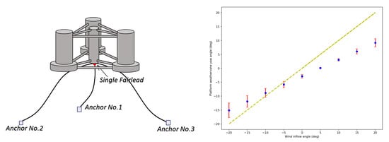
4]. The mooring system, as an essential part of the floating system for station keeping, is undergoing a quick update on the technology. One of the most recent developments is the concept of an FWT (Floating Wind Turbine) moored by an SPM (Single-Point Mooring) system [
5,
6,
7]. Iijima et al. [
5] designed a sample of an SPM-moored semisubmersible FWT and carried out a 1/100 scaled model test on the wave basin. Furthermore, it was observed that the FWT was capable of weathervaning. Koh et al. [
6] performed a numerical analysis of a single-point moored TLS (Tension Leg Spar) and found that the TLS also could self-adjust its orientation to the inflow wind direction. Nihei et al. [
7] carried out a tank model test of two different SPM bearing types and demonstrated that the combination usage of thrust bearing and aligning bearing perform better than using only the thrust bearing. From a technical point of view, the application of an SPM system enables the FWT to have free-yaw motions when the wind changes direction, which can be viewed as a passive yaw control system. In comparison to the active yaw control system normally installed in the turbine nacelle, the advantages of utilization of SPM can be generally summarized into the following two aspects:
To reduce the cost of construction and the heavy weight due to the existence of nacelle yaw control system and the associated mechanical bearings and brakes at the tower top of wind turbine;
To avoid the failure of a nacelle yaw system due to some sudden electricity-based accident or long-term corrosion caused by the humid salt-laden air in the sea circumstance.
SPM technology was firstly deployed in the offshore oil engineering, involving some FPSOs (Floating Production, Storage and Offloading units) and oil rigs [
8,
9,
10,
11,
12]. FPSOs have been successfully installed in North Sea, Brazil, Mediterranean Sea, etc. for offshore oil exploitations and are moored in a variety of sea-depth regions from shallow water (around 30 m) to ultra-deep water (2000–3000 m) [
12]. The SPM systems applied in FPSOs are usually turret-mooring systems in which the presence of a large number of risers results in large-diameter turrets [
13]. The weathervane capability of the SPM helps the self-adjusted FPSOs to be wave-aligned and therefore significantly reduces the wave impact on the FPSOs in harsh sea circumstances, due to the green water loadings, etc. [
14]. In recent years, the SPM technology has also been introduced into WECs (Wave Energy Converters). E.g., Thomsen et al. [
15,
16] tested and discussed the applicability of using SPM systems in the floating WECs, and compared its merits and demerits with other mooring concepts in order to reach an optimization of the levelized cost of energy.
The main objective of the present research is to investigate the characteristic behaviors of a semisubmersible FWT moored by an SPM system. The present work aims to reveal in which way the SPM system affects the dynamic response of a semisubmersible-type FWT. A comparative study is undertaken in the meantime with the MPM (Multiple-Point Mooring) system to conduct the analysis and draw meaningful conclusions. The research is done with the aid of a well-proven reliable numerical simulation software FAST (Fatigue, Aerodynamics, Structures, and Turbulence). FAST is the NREL’s (National Renewable Energy Laboratory’s) primary open-source CAE (Computer Aided Engineering) tool for simulating the coupled aero-hydro-servo-elastic dynamic response of wind turbines. It is based on advanced engineering models which are derived from fundamental laws, but with appropriate simplifications and assumptions, and supplemented where applicable with computational solutions and test data [
17]. In the present research, the latest FAST version 8.16 is used. This version has been developed based on the new modularization framework [
18,
19] to improve the overall modularity. In addition, in accordance with FAST version 8.16, several useful utilities and tool boxes written in Python and Matlab are also used for the purposes of pre-processing and post-processing. In the subsequent parts,
Section 2 presents the theories of the quasi-static and dynamic mooring modelling approaches for station keeping of the FWTs;
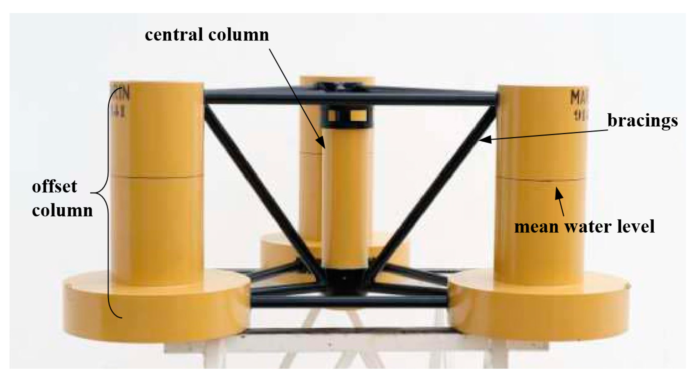
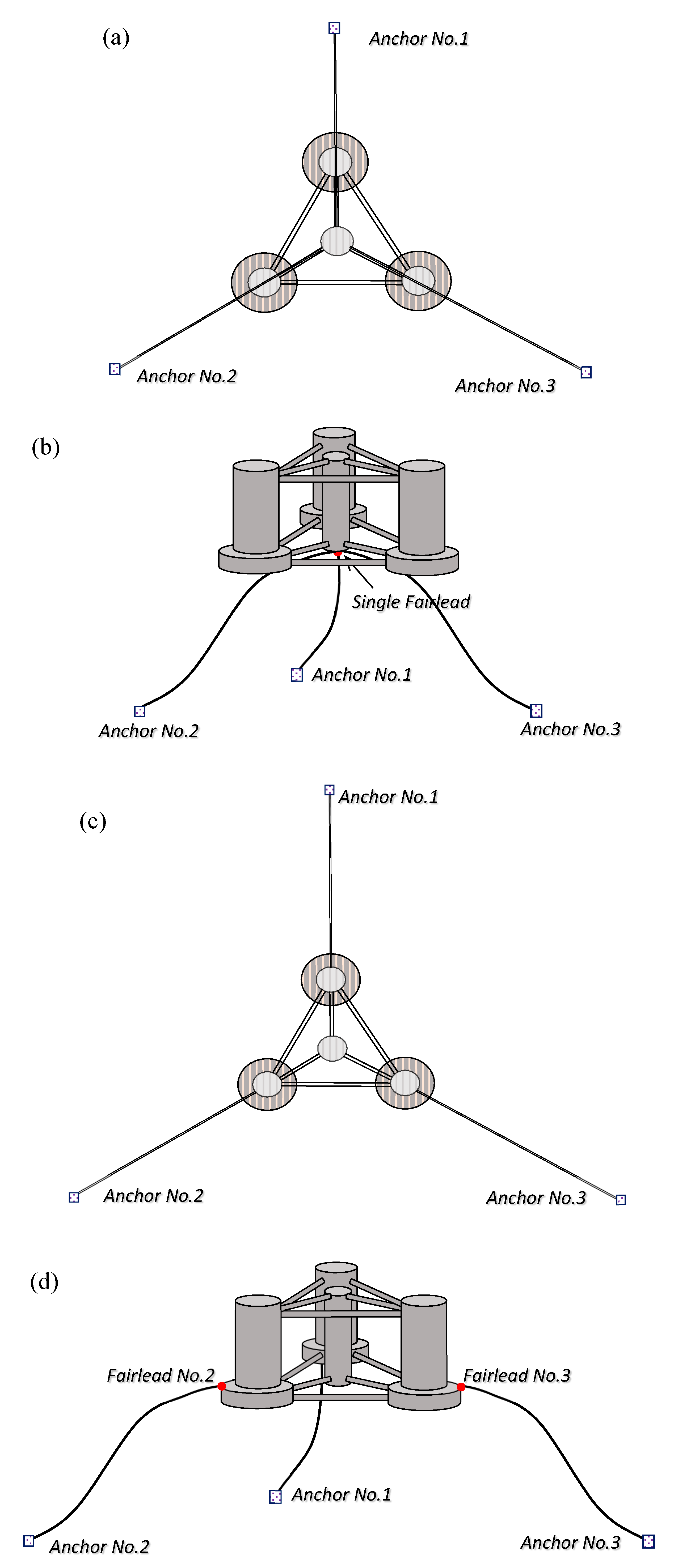
Section 3 describes in detail about the models of floating structure, wind turbine and mooring layouts;
Section 4 presents important computation results followed by analysis and discussions; the final conclusions are summarized in
Section 5.
2. Mathematical Equations of the Coupled Dynamics Theory of a Moored FWT
Equations of motion of a moored FWT can be derived based on the Kane’s equation [
20,
21,
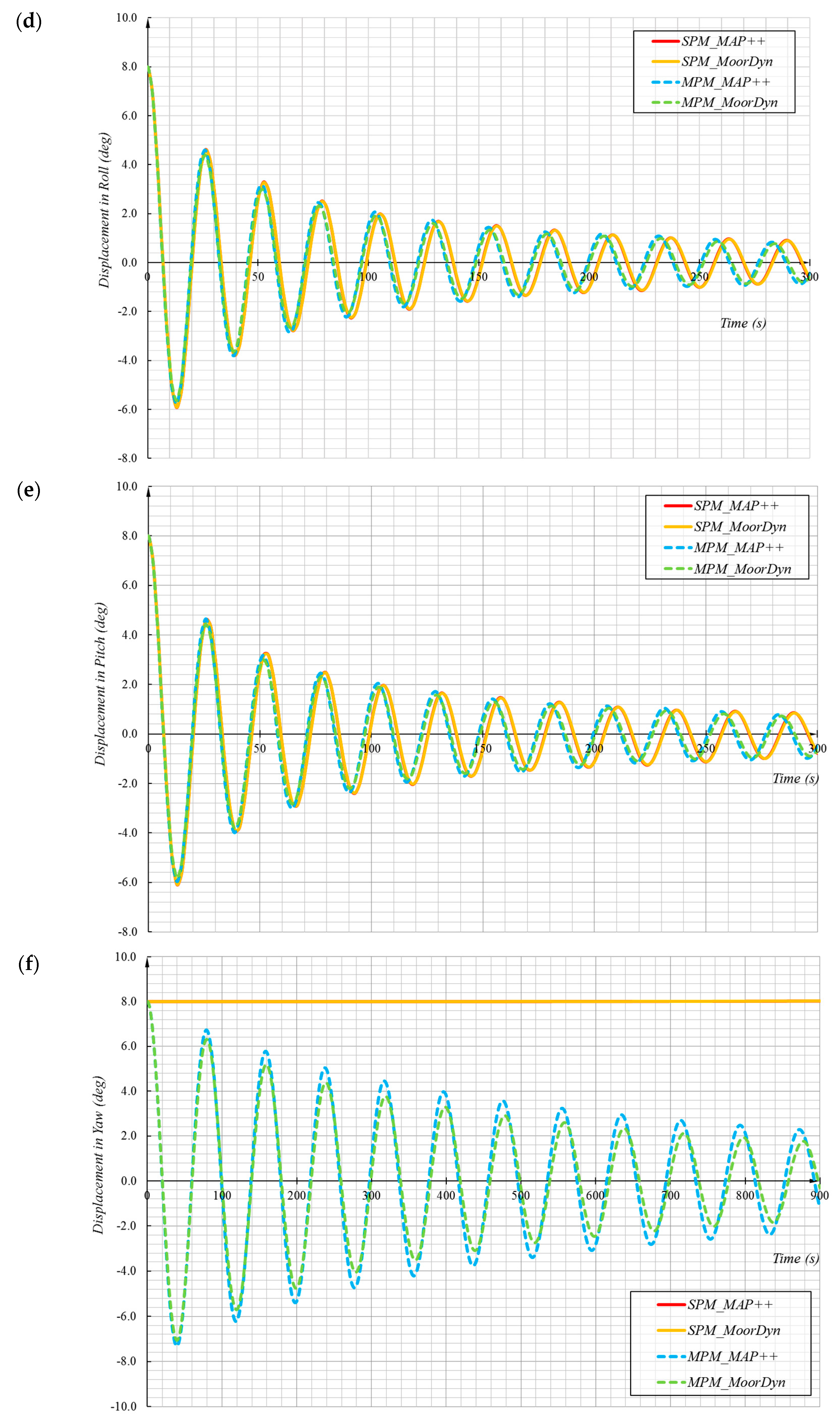
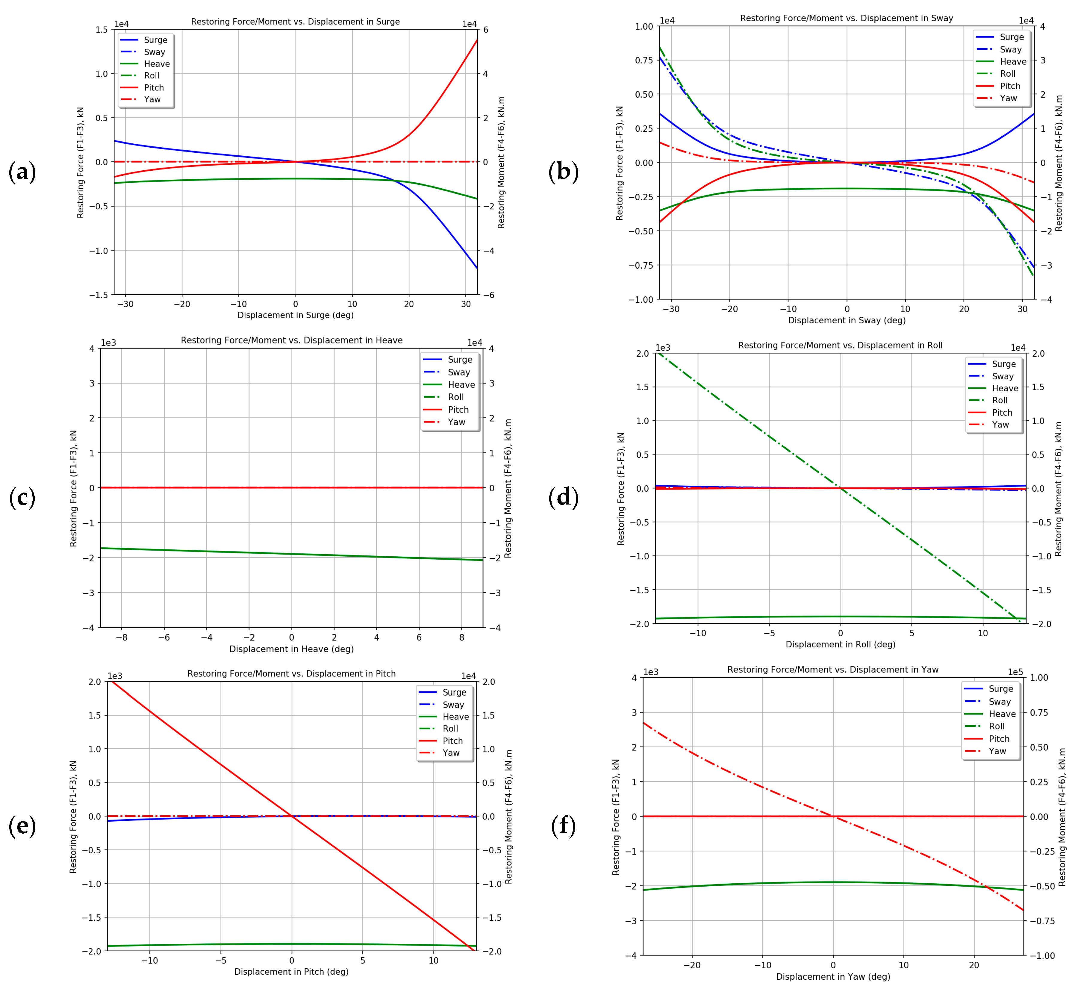
22], taking into consideration of all nonlinearities and system’s DOFs (Degrees of Freedom). Kane’s equation is generally based on the principle that all generalized active forces and inertial forces acting on the complex system of the coupled rotor-nacelle assembly, the tower and the support platform are balanced. The kinetics equations for the support platform include contributions from the platform mass and inertia, gravity, hydro-restoring, hydrodynamics and the reaction forces of the mooring system, which can be written as
where
,
and
are the (
i,
j) component of the platform mass matrix, impulsive hydrodynamic added-mass matrix and hydrostatic-restoring matrix, respectively;
is the
jth DOF of the platform motions;
represents the total excitation load on the support platform from incident waves;
is the (
i,
j) component of the matrix known as the wave-radiation-retardation kernel or impulse-response functions; the last term on the right-hand side of Equation (1) represents the buoyancy force of the platform derived from Archimedes’ principle, in which
is the water density,
g is the gravity acceleration,
V is the displaced volume of water by the immersed part of the platform,
is the (
i, 3) component of the Kronecker–Delta function;
is the
ith component of the load on platform from all mooring lines.
It can be noted that the first three terms on the right-hand side of Equation (1) are all linear to the platform acceleration, velocity and displacement, respectively.
and
can be linear or nonlinear, depending on the requisite modelling complexity. For a generic problem, usually up to second-order wave forces are considered for the potential flow theory. It is sometimes supplemented by the Morison-strip theory in the case there exist slender braced members in the floating platform structure (which is also nonlinear).
is usually modelled by a quasi-static method, e.g., the improved catenary theory [
22], to calculate the tension force of every mooring line and them make a summation of them. When no portion of the line rests on the seabed, the analytical formulation of each line is as follows:
where
and
are respectively the horizontal and vertical coordinates of the fairlead position relative to the anchor,
and
are the horizontal and vertical components of the effective tension in the mooring line at the fairlead,
w is the mass of the mooring line per unit length,
L is the total unstretched mooring line length, and
EA is the sectional stiffness of the mooring line. It is worth noting that Equations (2) and (3) should be solved iteratively in the local coordinate system via the Newton–Raphson method, etc.
When the environment conditions are severe or if the floating platform has large responses, high-fidelity mooring line models are recommended for the mooring analysis, especially for prediction of the mooring line loads. The existing high-fidelity models include FEA-based models and lumped-mass models. It appears that, although the FEA-based models can reach a good accuracy in prediction of the loads over a wide range of conditions, they are not computationally cost-effective [
23]. In a lumped-mass model, the cable mass is discretized into point masses at every separate node by assigning it half of the combined mass of two adjacent cable segments. The complete equation of motion for each node
i is [
23]
where
and
stands for the mass and added mass assigned at the node
i,
T and
B stands for the internal stiffness and damping,
W and
F stands for the line net buoyancy and seabed contact,
and
stands for the hydrodynamic drag force in the transverse and tangential directions, respectively. All of the above symbols in bold are 3 × 3 matrices.
Regarding the difference of the two mooring-line modelling methods, studies have been done previously by many other researchers. Thomsen et al. [
15] stated that a quasi-static approach is not suitable to study the dynamic behavior of WECs when the mooring has significant nonlinearities, e.g., especially for synthetic ropes. It was later proved by their experimental testing of moorings for large floating wave energy converters in the wave basin at Aalborg University, in which a large 52% deviation was found by comparing with their measured line tension [
24]. Hall et al. [
25] concluded that mooring dynamics have an influence on platform motions only when those motions are large, but are always important to the prediction of mooring line loads. Wendt et al. [
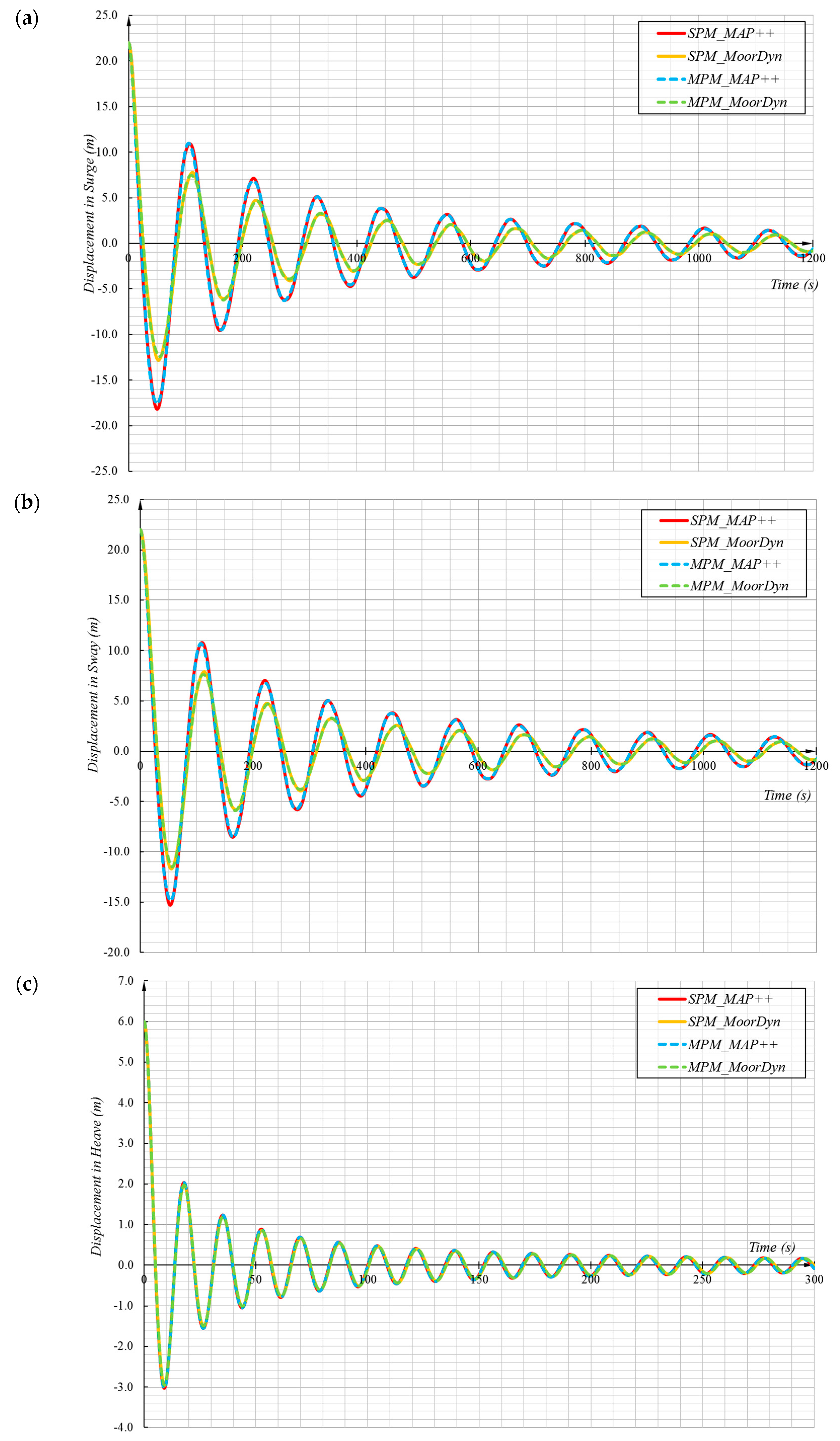
26] performed a thorough quantified comparison between the dynamic mooring and the quasi-static methods, showing that the lumped-mass method predicts smaller platform motions but larger mooring line tensions in the extensive presented results.

 ,
, 


