Asymptotic Analysis for the Effects of Anode Inlet Humidity on the Fastest Power Attenuation Single Cell in a Vehicle Fuel Cell Stack

Abstract
:1. Introduction
2. Calculation
2.1. ARH Model Description
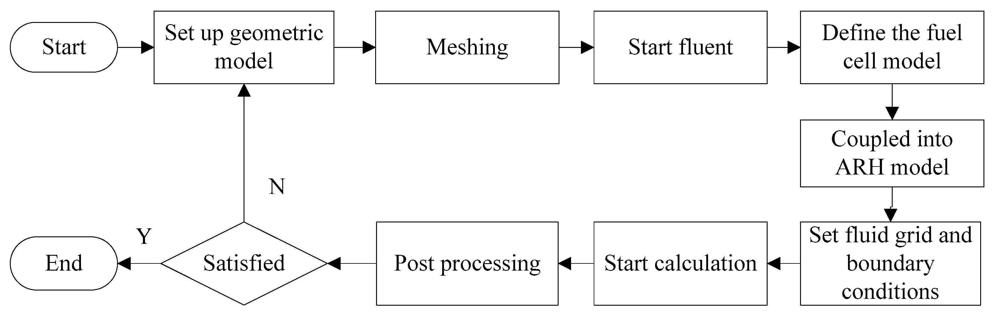
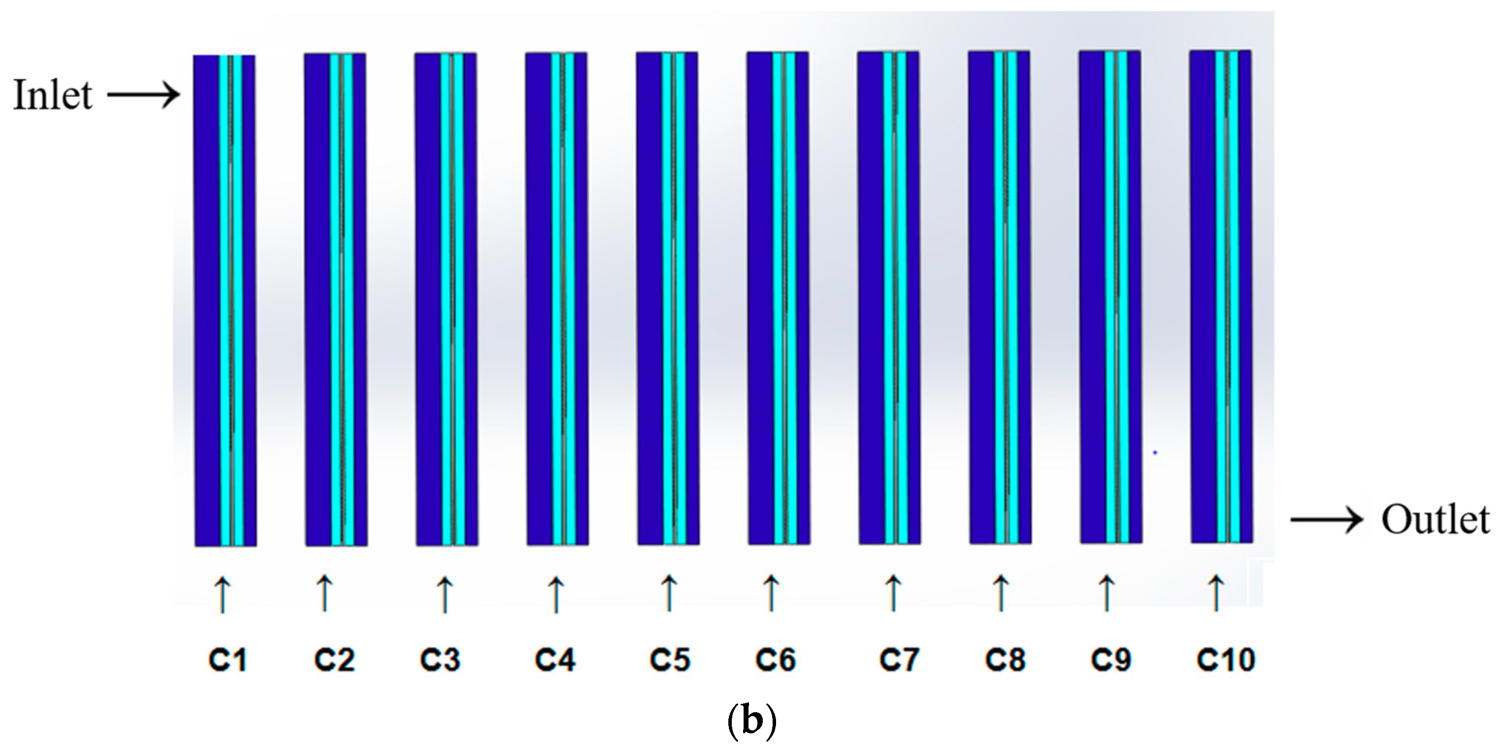
2.2. Simulation Schematic
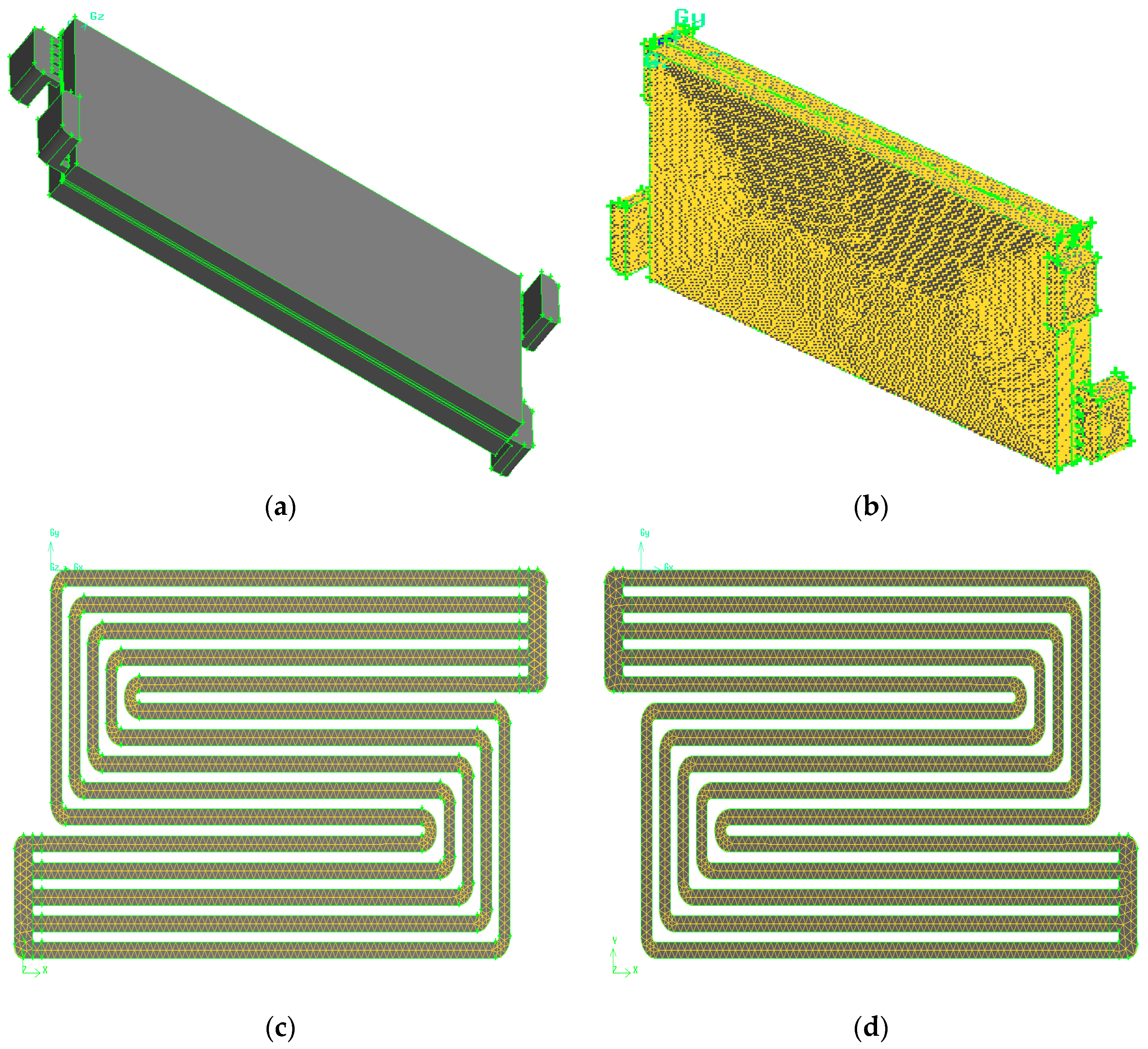
2.3. Geometry and Mesh Generation
3. Experimental Set-Up
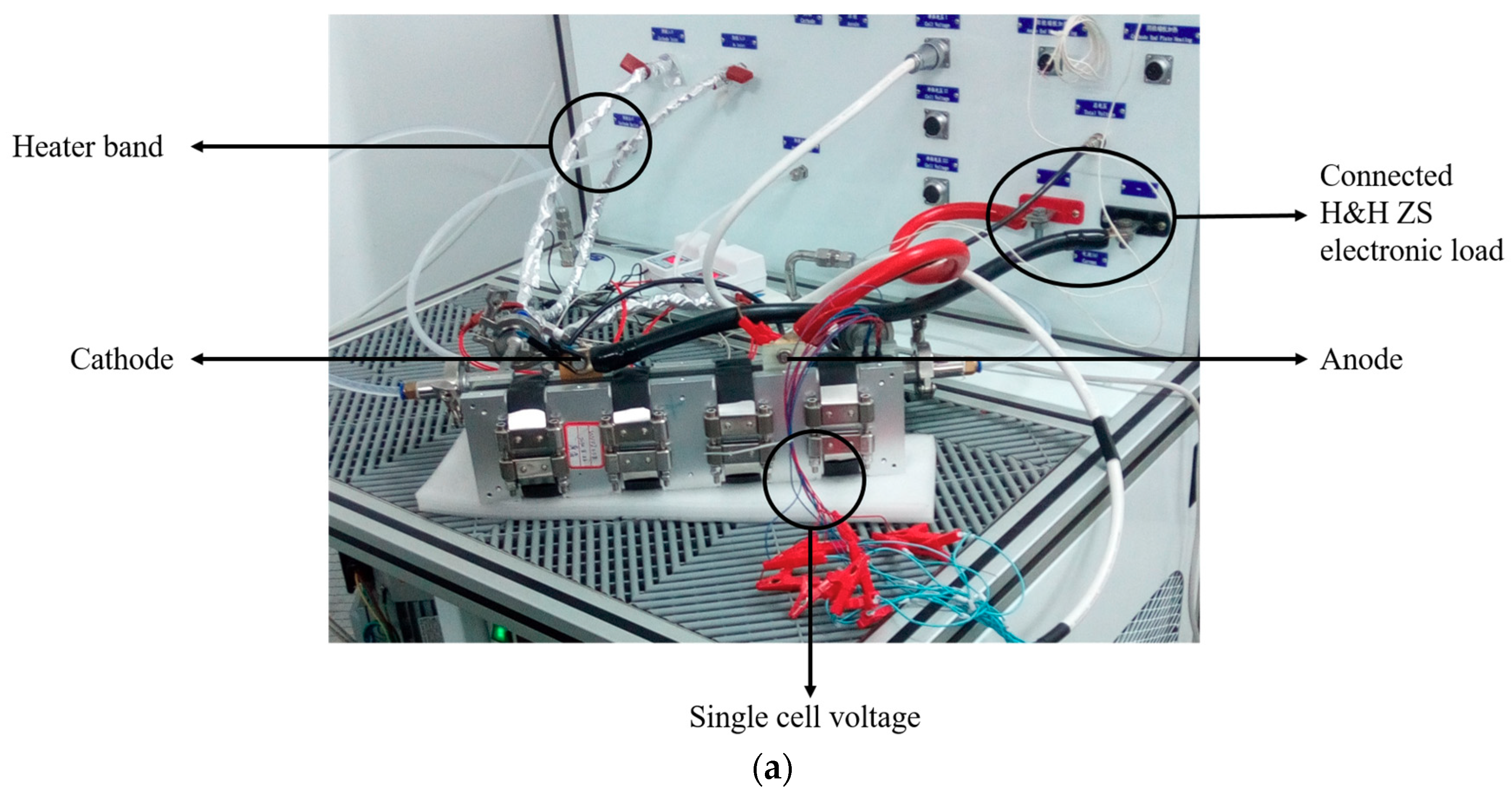
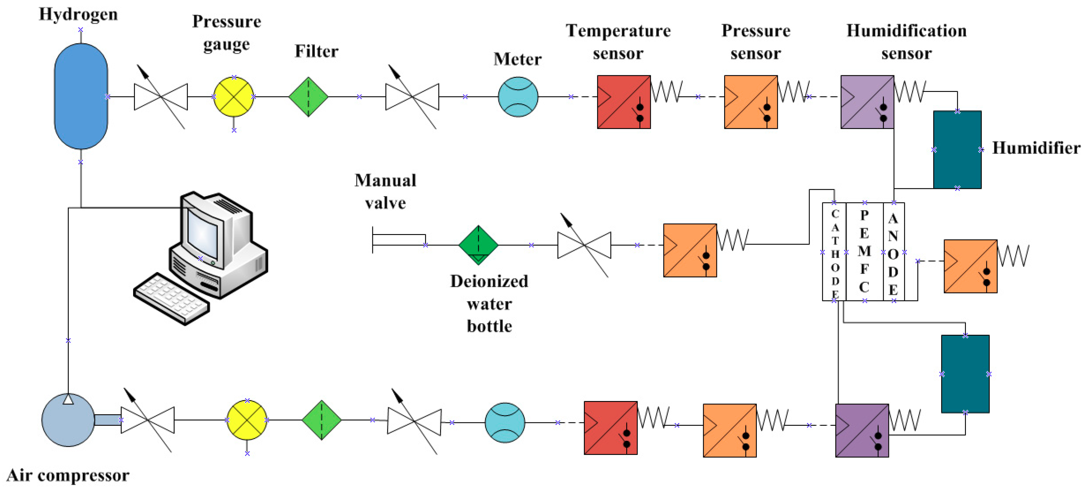
3.1. Apparatus and Schematic
3.2. Experimental Conditions
4. Results and Discussion
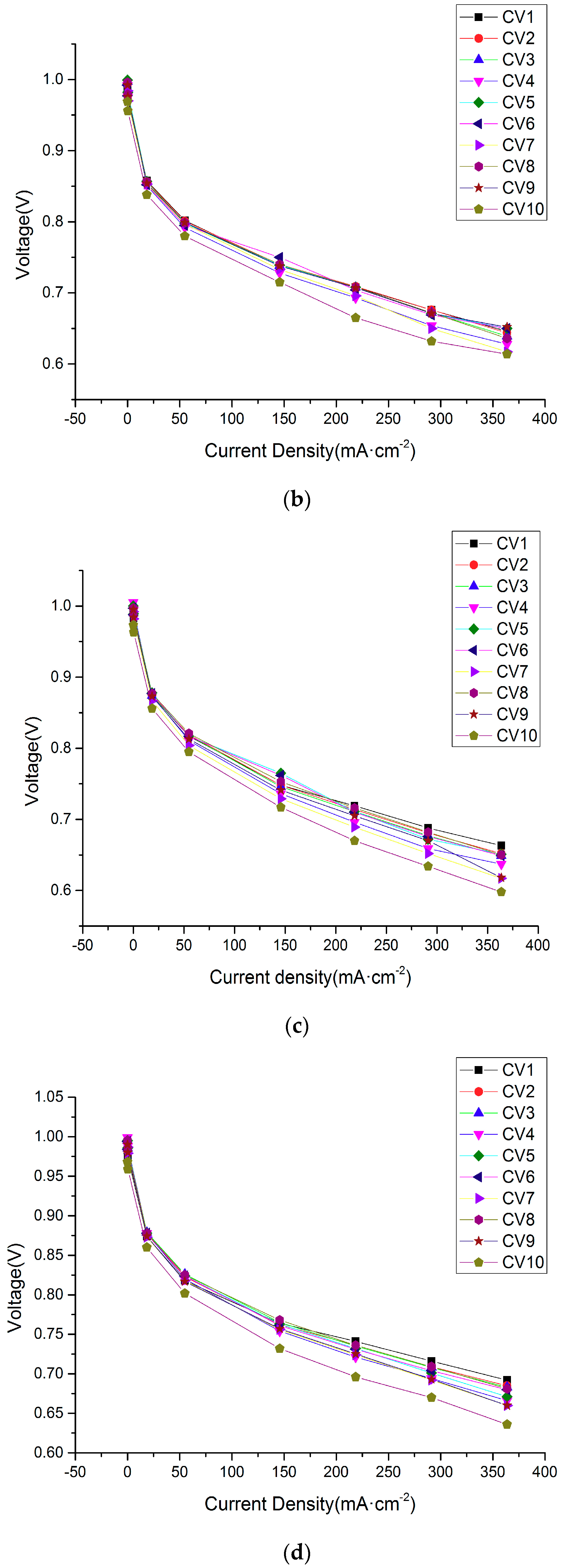
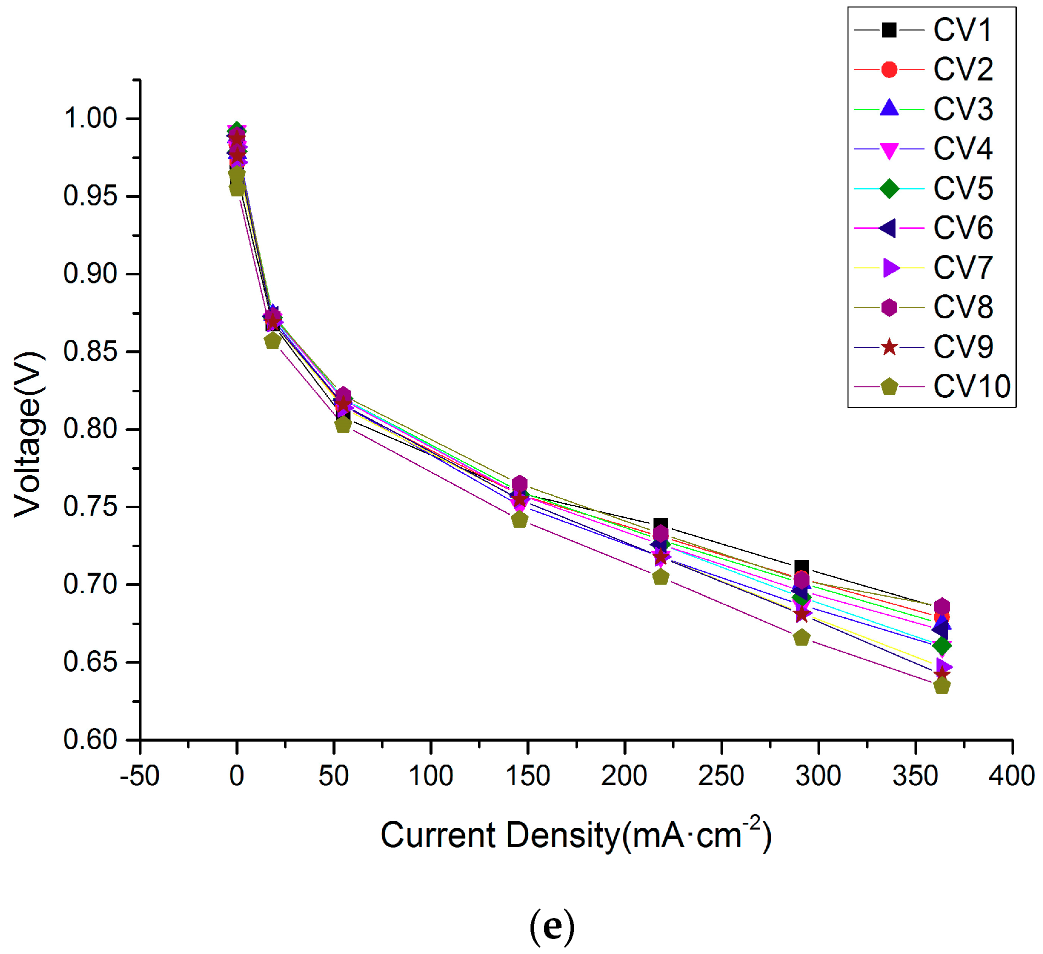
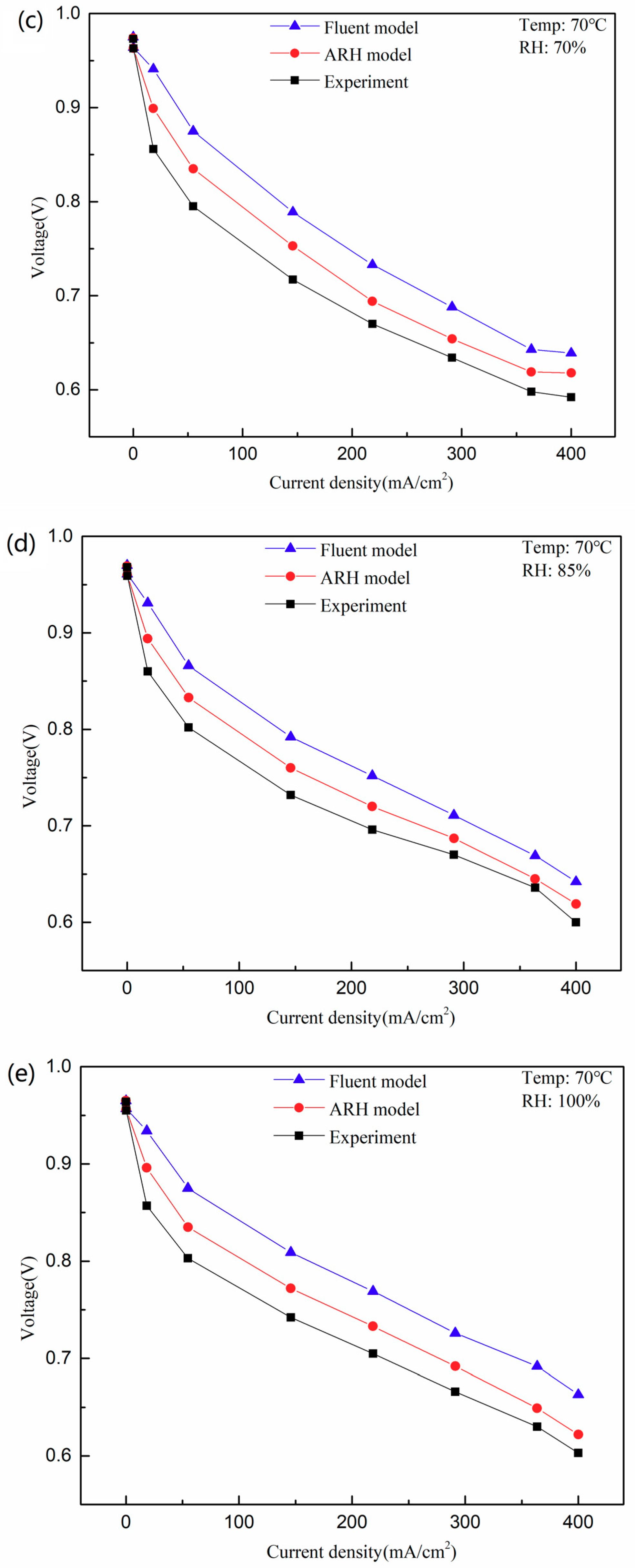
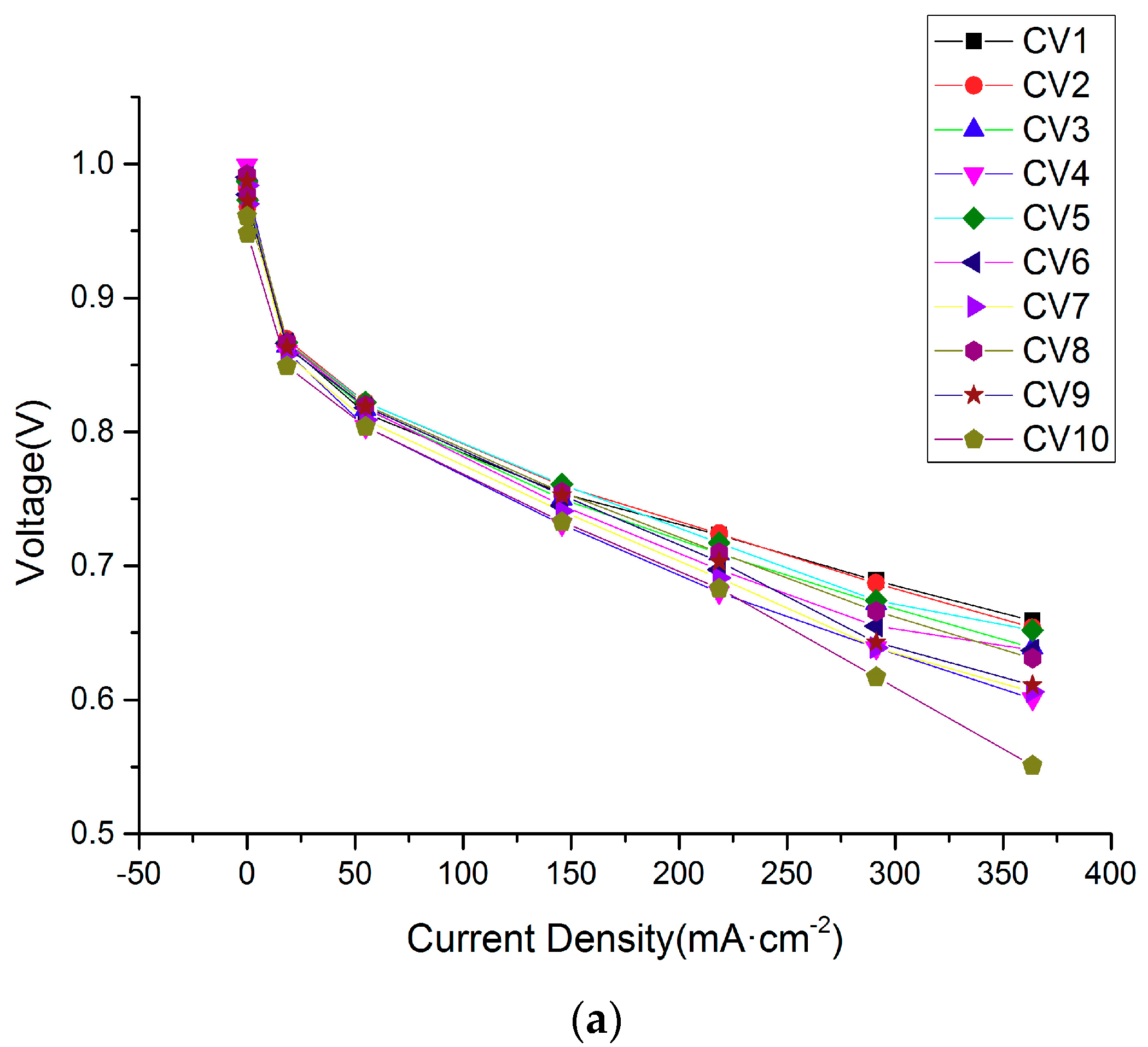
4.1. Polarization Curves with 10 Single Cells
4.2. The Fastest Power Attenuation Single Cell
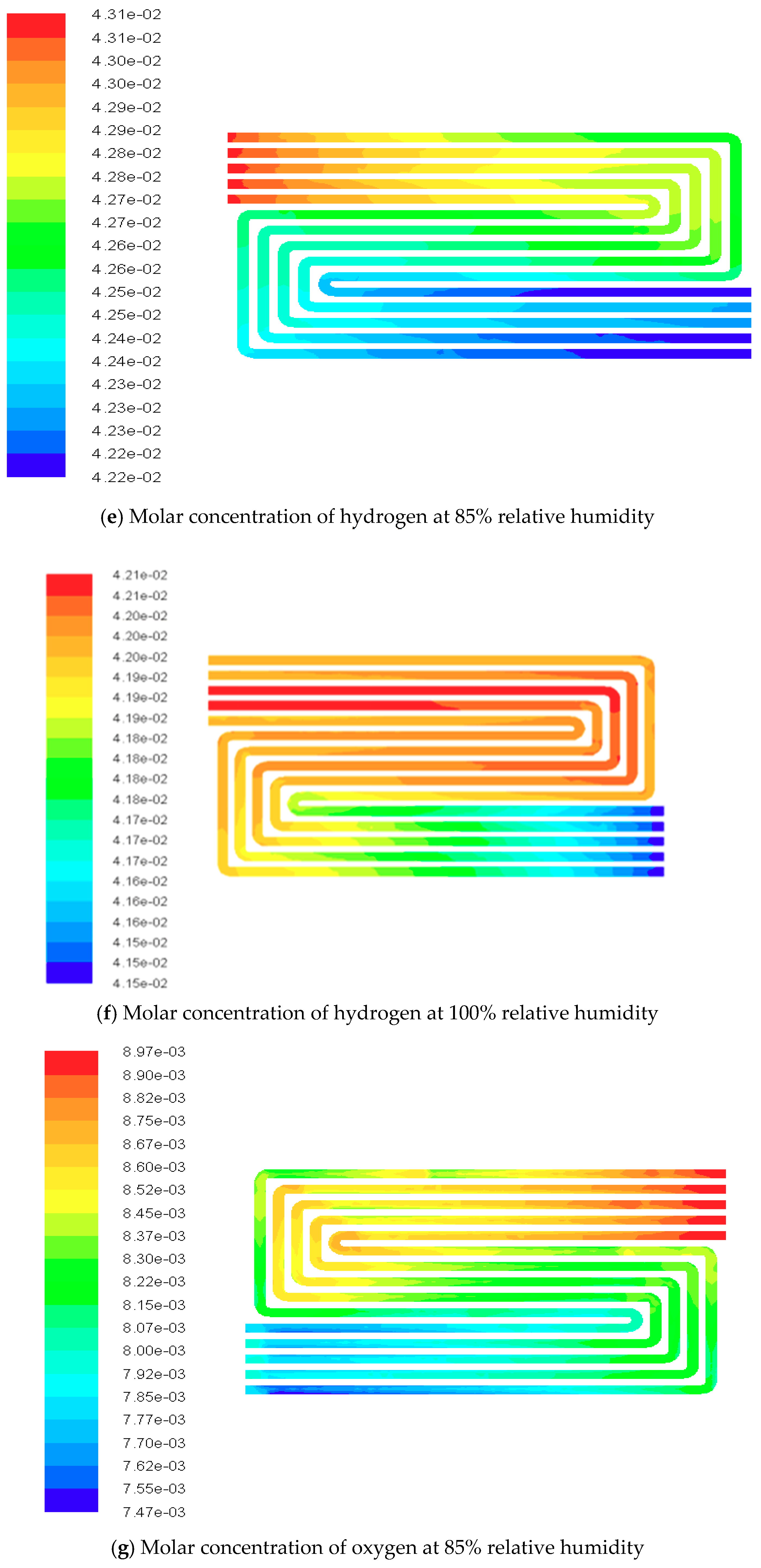
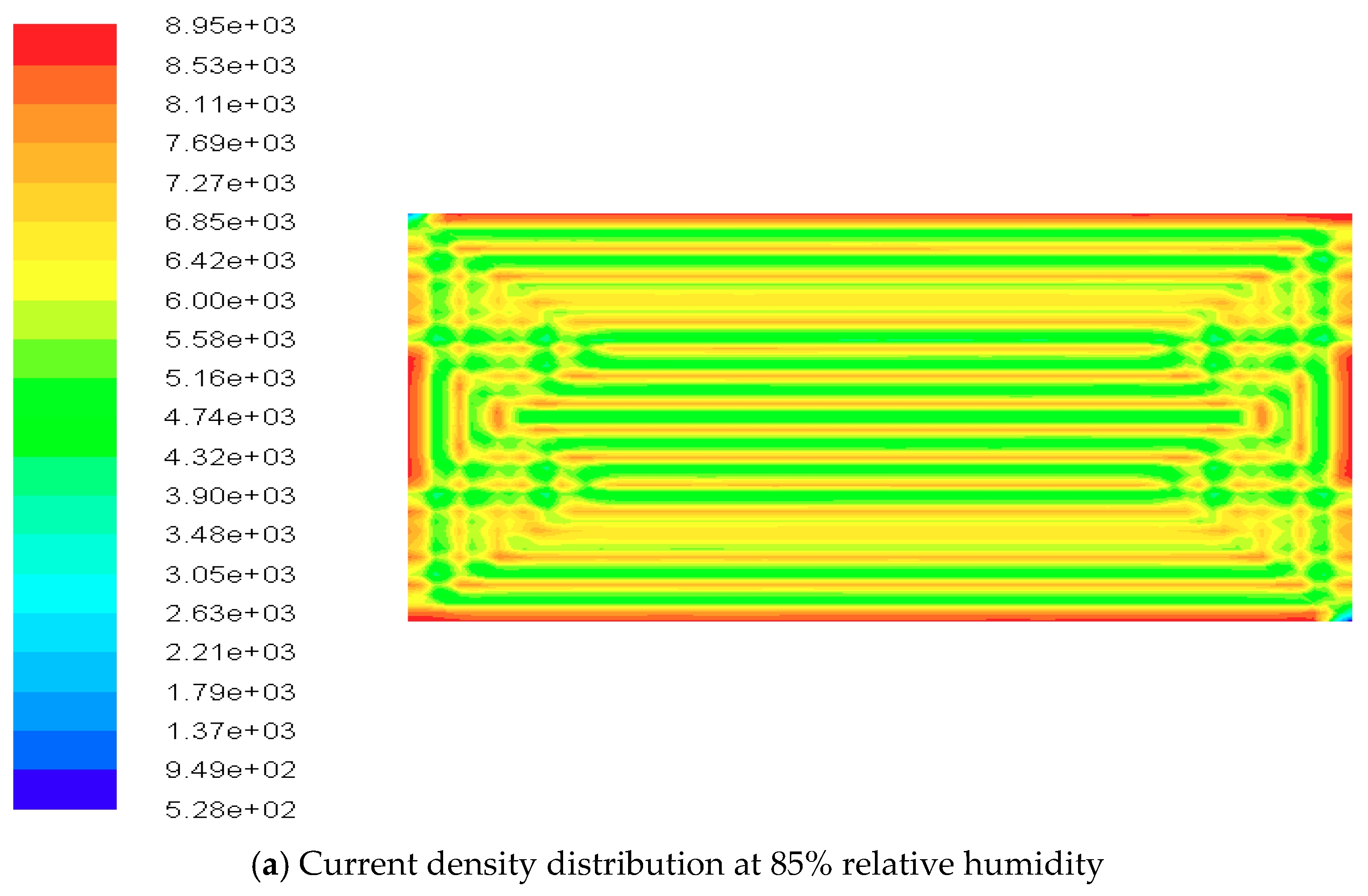
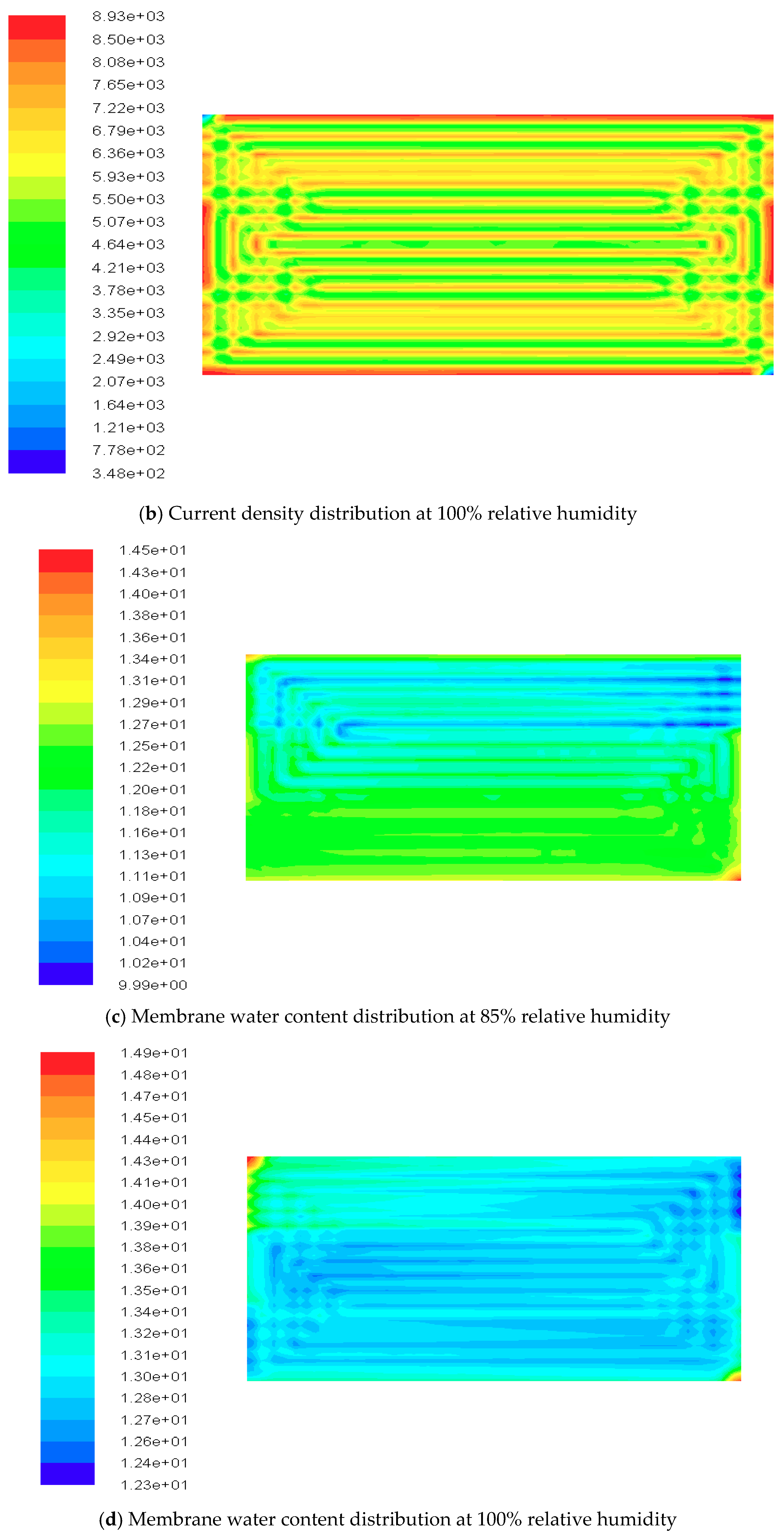
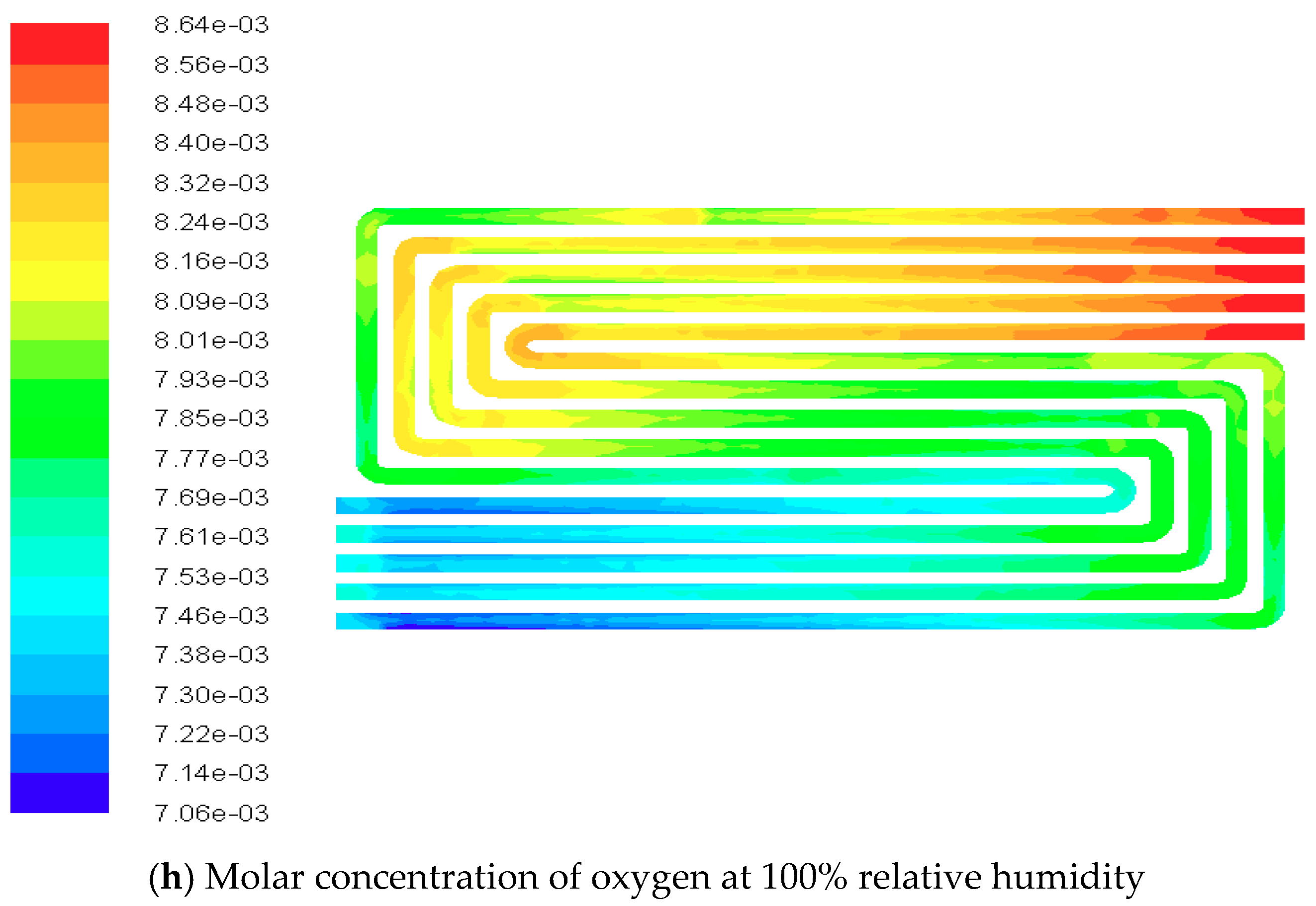
4.3. Contours of Fuel Cell Species Distribution
5. Conclusions
- (1)
- Single cell C10 power attenuation is the fastest, and its performance is the poorest under these experimental conditions.
- (2)
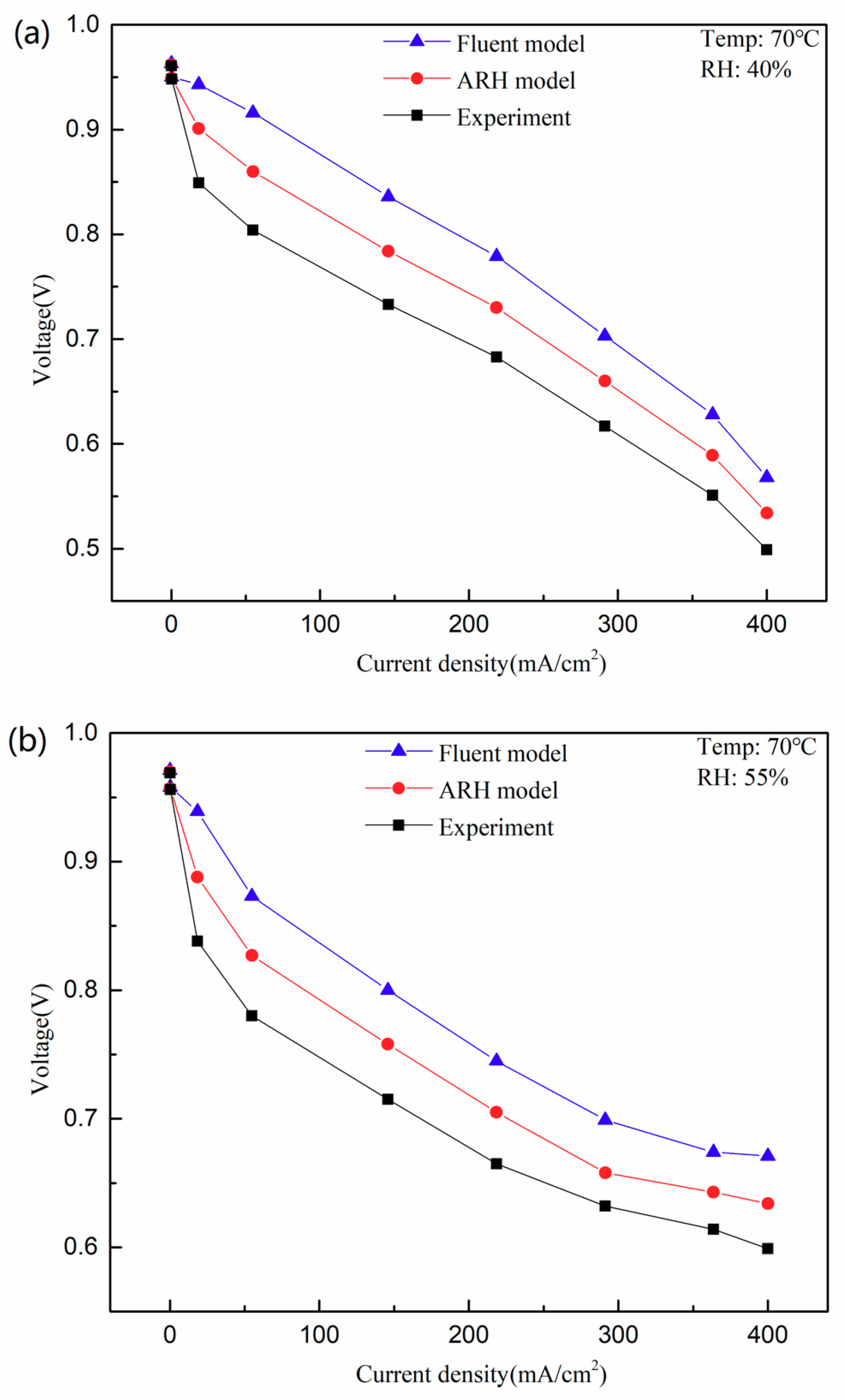
- The ARH model is valid because C10 experimental results and polarization curves predicted by the ARH model and the Fluent original model are consistent. ARH model results are closer to the experiment results, especially because its calculation deviation is almost 28% less than original model at a current density of 360 mA·cm−2 for a relative humidity of 85%.
Author Contributions
Funding
Conflicts of Interest
References
- Vesselin, K.K.; Giacomo, F.; Elio, J.; Mariagiovanna, M.; Raffaello, C. 3D CFD modeling and experimental characterization of HT PEM fuel cells at different anode gas compositions. Int. J. Hydrog. Energy 2014, 39, 21663–21672. [Google Scholar]
- Liu, Y.; Werner, L.; Holger, J.; Remzi, C.S.; Detlef, S. A review of high-temperature polymer electrolyte membrane fuel-cell (HT-PEMFC)-based auxiliary power units for diesel-powered road vehicles. J. Power Sources 2016, 311, 91–102. [Google Scholar] [CrossRef]
- Alexandre, D.B. Synthesis on power electronics for large fuel cells: From power conditioning to potentiodynamic analysis technique. Energy Convers. Manag. 2014, 84, 174–185. [Google Scholar]
- Fragiacomo, P.; Astorino, E.; Chippari, G.; Lorenzo, G.D.; Czarnetzki, W.T.; Schneider, W. Dynamic modeling of a hybrid electric system based on an anion exchange membrane fuel cell. Cogent Eng. 2017, 4. [Google Scholar] [CrossRef]
- Lorenzo, G.D.; Andaloro, L.; Sergi, F.; Napoli, G.; Ferraro, M.; Antonucci, V. Numerical simulation model for the preliminary design of hybrid electric city bus power train with polymer electrolyte fuel cell. Int. J. Hydrog. Eng. 2014, 39, 12934–12947. [Google Scholar] [CrossRef]
- Napoli, G.; Micari, S.; Dispenza, G.; Novo, S.D.; Antonucci, V.; Andaloro, L. Development of a fuel cell hybrid electric powertrain: A real case study on a Minibus application. Int. J. Hydrog. Energy 2017, 42, 28034–28047. [Google Scholar] [CrossRef]
- De Luca, D.; Fragiacomo, P.; De Lorenzo, G.; Czarnetzki, W.T.; Schneider, W. Strategies for dimensioning two-wheeled fuel cell hybrid electric vehicles using numerical analysis software. Fuel Cells 2016, 16, 628–639. [Google Scholar] [CrossRef]
- Andaloro, L.; Micari, S.; Napolo, G.; Polimeni, A.; Antonucci, V. A hybrid electric fuel cell minibus: Drive test. World Electr. Veh. J. 2016, 8, 131–138. [Google Scholar] [CrossRef]
- Ebranhim, A.; Nasser, B.H. Performance analysis of a membrane humidifier containing porous metal foam as flow distributor in a PEM fuel cell system. Energy Convers. Manag. 2014, 88, 612–621. [Google Scholar]
- Lei, X.; Prodip, K.D.; Song, X.; Mohamed, M.; Keith, S. Numerical analysis of the optimum membrane/ionomer water content of PEMFCs: The interaction of Nafion ionomer content and cathode relative humidity. Appl. Energy 2015, 138, 242–257. [Google Scholar]
- Saadi, A.; Becherif, M.; Hissel, D.; Ramadan, H.S. Dynamic modeling and experimental analysis of PEMFCs: A comparative study. Int. J. Hydrog. Energy 2017, 42, 1544–1557. [Google Scholar] [CrossRef]
- Allaoua, B.; Asnoune, K.; Mebarki, B. Energy management of pem fuel cell/supercapacitor hybrid power sources for an electric vehicle. Int. J. Hydrog. Energy 2017, 42, 21158–21161. [Google Scholar] [CrossRef]
- Park, S.K.; Choe, S.Y. Modeling and Experimental Analyses of a Two-Cell Polymer Electrolyte Membrane Fuel Cell Stack Emphasizing Individual Cell Characteristics. J. Fuel Cell. Sci. Tech. 2009, 6, 25–34. [Google Scholar] [CrossRef]
- Miller, M.; Bazylak, A. A review of polymer electrolyte membrane fuel cell stack testing. J. Power Source 2011, 196, 601–613. [Google Scholar] [CrossRef]
- Hao, Y.; Nakajima, H.; Yoshizumi, H.; Inada, A.; Sasaki, K.; Ito, K. Characterization of an electrochemical hydrogen pump with internal humidifier and dead-end anode channel. Int. J. Hydrog. Energy 2016, 41, 13879–13887. [Google Scholar] [CrossRef]
- Fan, L.; Zhang, G.; Jiao, K. Characteristics of PEMFC operating at high current density with low external humidification. Energy Convers. Manag. 2017, 150, 763–774. [Google Scholar] [CrossRef]
- Vasu, G.; Tangirala, A.K.; Viswanathan, B.; Dhahthathreyan, K.S. Continuous bubble humidification and control of relative humidity of H for a PEMFC system. Int. J. Hydrog. Energy 2008, 33, 4640–4648. [Google Scholar] [CrossRef]
- Kong, I.M.; Jung, A.; Kim, S.M. Investigations on the double gas diffusion backing layer for performance improvement of self-humidified proton exchange membrane fuel cells. Appl. Energy 2016, 176, 149–156. [Google Scholar] [CrossRef]
- Zhao, X.; Xu, L.; Fang, C.; Jiang, H.; Li, J.; Ouyang, M. Study on voltage clamping and self-humidification effects of PEM fuel cell system with dual recirculation based on orthogonal test method. Int. J. Hydrog. Energy 2018, 43, 16268–16278. [Google Scholar] [CrossRef]
- Sridhar, P.; Ramkumar, P.; Rajalakshmi, N.; Raja, M.; Dhathathreyan, K.S. Humidification studies on polymer electrolyte membrane fuel cell. J. Power Source 2001, 101, 72–78. [Google Scholar] [CrossRef]
- Zhang, H.; Qian, Z.; Yang, D.; Ma, X. Design of an air humidifier for a 5 kW proton exchange membrane fuel cell stack operated at elevated temperatures. Int. J. Hydrog. Energy 2013, 38, 12353–12362. [Google Scholar] [CrossRef]
- Pei, P.; Chen, H. Main factors affecting the lifetime of Proton Exchange Membrane fuel cells in vehicle applications: A review. Appl. Energy 2014, 125, 60–75. [Google Scholar] [CrossRef]
- Dilek, N.O.; Bora, T.; Kemal, A. Effects of operation temperature and reactant gas humidity levels on performance of PEM fuel cells. Renew. Sustain. Energy Rev. 2016, 59, 1298–1306. [Google Scholar]
- Eckl, R.; Zehtner, W.; Leu, C.; Wagner, U. Experimental analysis of water management in a self-humidifying polymer electrolyte fuel cell stack. J. Power Source 2004, 138, 137–144. [Google Scholar] [CrossRef]
- Jeon, S.W.; Cha, D.; Kim, H.S.; Kim, Y. Analysis of the system efficiency of an intermediate temperature proton exchange membrane fuel cell at elevated temperature and relative humidity conditions. Appl. Energy 2016, 166, 165–173. [Google Scholar] [CrossRef]
- Sveshnikova, A.; Abrosimov, K.; Khayrullina, A.; Ustinov, A. Effect of ambient air conditions on PEM fuel cell performance. J. Renew. Sustain. Energy 2017, 9. [Google Scholar] [CrossRef]
- Jeon, D.H.; Kim, K.N.; Baek, S.M.; Nam, J.H. The effect of relative humidity of the cathode on the performance and the uniformity of PEM fuel cells. Int. J. Hydrog. Energy 2011, 36, 12499–12511. [Google Scholar] [CrossRef]
- Albrto, G.; Abhishek, R.; Agus, P.S.; Tariq, S. Effect of operating parameters on the transient performance of a polymer electrolyte membrane fuel cell stack with a dead-end anode. Appl. Energy 2014, 130, 692–701. [Google Scholar]
- Chen, H.; Zhao, X.; Qu, B.; Zhang, T.; Pei, P.; Li, C. An evaluation method of gas distribution quality in dynamic process of proton exchange membrane fuel cell. Appl. Energy 2018, 232, 26–35. [Google Scholar] [CrossRef]
- Pei, P.; Song, M.; Zeng, X.; Hongsan, Z. Flooding prediction based on characteristics of hydrogen pressure drop in PEMFC. Trans. Chin. Soc. Agric. Mach. 2014, 45, 341–346. [Google Scholar]
- Falcao, D.S.; Gomes, P.J.; Oliveira, V.B.; Pinho, C.; Pinto, A.M.F.R. 1D and 3D numerical simulations in PEM fuel cells. Int. J. Hydrog. Energy 2011, 36, 12486–12498. [Google Scholar] [CrossRef]
- Rahimi-Esbo, M.; Ranjbar, A.A.; Ramiar, A.; Alizadeh, E.; Aghaee, M. Improving PEM fuel cell performance and effective water removal by using a novel gas flow field. Int. J. Hydrog. Energy 2016, 41, 3023–3037. [Google Scholar] [CrossRef]
- Jang, J.; Chiu, H.; Yan, W.; Sun, W. Effects of operating conditions on the performances of individual cell and stack of PEM fuel cell. J. Power Sources 2008, 180, 476–483. [Google Scholar] [CrossRef]
- Li, W.; Zhang, Q.; Wang, C.; Yan, X.; Shen, S.; Xia, G.; Zhu, F.; Zhang, J. Experimental and numerical analysis of a three-dimensional flow field for PEMFCs. Appl. Energy 2017, 195, 278–288. [Google Scholar] [CrossRef]
- Zhang, Q.; Lin, R.; Techer, L.; Cui, X. Experimental study of variable operating parameters effects on overall PEMFC performance and spatial performance distribution. Energy 2016, 115, 550–560. [Google Scholar] [CrossRef]
- Hartung, I.; Kirsch, S.; Zihrul, P.; Muller, O.; von Unwerth, T. Improved electrochemical in-situ characterization of polymer electrolyte membrane fuel cell stacks. J. Power Sources 2016, 307, 280–288. [Google Scholar] [CrossRef]
- Takalloo, P.K.; Nia, E.S.; Ghazikhani, M. Numerical and experimental investigation on effects of inlet humidity and fuel flow rate and oxidant on the performance on polymer fuel cell. Energy Convers. Manag. 2016, 114, 290–302. [Google Scholar] [CrossRef]
- Gomez, A.; Sasmito, A.P.; Shamim, T. Investigation of the purging effect on a dead-end anode PEM fuel cell-powered vehicle during segments of a European driving cycle. Energy Convers. Manag. 2015, 106, 951–957. [Google Scholar] [CrossRef]
- Machdo, B.S.; Chakraborty, N.; Das, P.K. Influences of flow direction, temperature and relative humidity on the performance of a representative anion exchange membrane fuel cell: A computational analysis. Int. J. Hydrog. Energy 2017, 42, 6310–6323. [Google Scholar] [CrossRef]
- Sohn, Y.J.; Choi, J.I.; Kim, K. Numerical analysis on water transport in alkaline anion exchange membrane fuel cells. Electrochemitry 2015, 83, 80–83. [Google Scholar] [CrossRef]
- Chippar, P.; Kang, K.; Lim, Y.; Kim, W.; Ju, H. Effects of inlet relative humidity (RH) on the performance of a high temperature-proton exchange membrane fuel cell (HT-PEMFC). Int. J. Hydrog. Energy 2014, 39, 2767–2775. [Google Scholar] [CrossRef]


| Parameters | Value | Unit |
|---|---|---|
| Active area | 0.0034 | m2 |
| Thickness of the membrane | 0.00005 | m |
| Thickness of the diffusion layer | 0.0002 | m |
| Thickness of the catalyst layer | 0.00001 | m |
| Length of the flow channel | 0.05 | m |
| Width of the flow channel | 0.0012 | m |
| Depth of the hydrogen channel | 0.0006 | m |
| Depth of the oxygen channel | 0.0008 | m |
| Thickness of the collector plate | 0.002 | m |
| Number of serpentine turns | 5 | |
| Length of the single channel turn | 0.05 | m |
| Thermal conductivity of the membrane | 0.4 | W (m K)−1 |
| Thermal conductivity of the gas diffusion layer | 1.2 | W (m K)−1 |
| Thermal conductivity of the catalyst layer | 1.5 | W (m K)−1 |
| Thermal conductivity of the current collector | 20 | W (m K)−1 |
| Electrical conductivity of the gas diffusion layer | 2500 | (ohm m)−1 |
| Electrical conductivity of the catalyst layer | 2500 | (ohm m)−1 |
| Electrical conductivity of the current collector | 20,000 | (ohm m)−1 |
| Porosity of the gas diffusion layer | 0.5 | |
| Porosity of the catalyst layer | 0.28 | |
| Membrane equivalent weight | 1100 | kg kmol−1 |
| Hydrogen reference exchange current density | 4000 | A m−2 |
| Anode reference concentration | 1 | kmol m−3 |
| Anode transfer coefficient | 0.5 | |
| Oxygen reference exchange current density | 5.75 | A m−2 |
| Cathode reference concentration | 1 | kmol m−3 |
| Cathode transfer coefficient | 0.5 | |
| Open circuit voltage | 0.95 | V |
| Leakage current | 0 | A |
| Electrochemical equivalent of hydrogen | 1.05 × 10⁻⁸ | kg (A s)−1 |
| Electrochemical equivalent of oxygen | 8.29 × 10⁻⁸ | kg (A s)−1 |
| Reference diffusivity of hydrogen | 9.15 × 10⁻⁵ | m2 s−1 |
| Reference diffusivity of oxygen | 2.2 × 10⁻⁵ | m2 s−1 |
| Reference diffusivity of water | 2.56 × 10⁻⁵ | m2 s−1 |
| Anode catalyst layer surface/volume ratio | 2 × 10⁶ | m−1 |
| Cathode catalyst layer surface/volume ratio | 1 × 10⁷ | m−1 |
| Operating temperature | 70 | °C |
| Anode relative humidity | 40, 55, 70, 85, 100 | % |
| Cathode relative humidity | 100 | % |
| Current Density (mA/cm2) | CV1 | CV2 | CV3 | CV4 | CV5 | CV6 | CV7 | CV8 | CV9 | CV10 | Voltage |
|---|---|---|---|---|---|---|---|---|---|---|---|
| 0.012 | 0.978 | 0.982 | 0.992 | 0.999 | 0.987 | 0.990 | 0.984 | 0.992 | 0.987 | 0.961 | 9.840 |
| 18.494 | 0.865 | 0.869 | 0.864 | 0.860 | 0.867 | 0.866 | 0.858 | 0.867 | 0.863 | 0.849 | 8.613 |
| 54.861 | 0.814 | 0.822 | 0.817 | 0.804 | 0.822 | 0.818 | 0.809 | 0.820 | 0.819 | 0.804 | 8.109 |
| 145.783 | 0.754 | 0.760 | 0.750 | 0.731 | 0.761 | 0.745 | 0.741 | 0.755 | 0.753 | 0.733 | 7.459 |
| 218.502 | 0.723 | 0.724 | 0.709 | 0.680 | 0.717 | 0.697 | 0.691 | 0.710 | 0.703 | 0.683 | 7.010 |
| 291.222 | 0.689 | 0.687 | 0.672 | 0.639 | 0.674 | 0.655 | 0.639 | 0.666 | 0.643 | 0.617 | 6.561 |
| 363.595 | 0.659 | 0.654 | 0.639 | 0.601 | 0.652 | 0.637 | 0.606 | 0.631 | 0.611 | 0.551 | 6.158 |
| Voltage drop (V) | 0.319 | 0.328 | 0.353 | 0.398 | 0.335 | 0.353 | 0.378 | 0.361 | 0.376 | 0.410 | 3.683 |
| Current Density (mA/cm2) | CV1 | CV2 | CV3 | CV4 | CV5 | CV6 | CV7 | CV8 | CV9 | CV10 | Voltage |
|---|---|---|---|---|---|---|---|---|---|---|---|
| 0.012 | 0.988 | 0.993 | 0.997 | 0.992 | 0.999 | 0.992 | 0.984 | 0.996 | 0.992 | 0.969 | 9.891 |
| 18.494 | 0.858 | 0.857 | 0.856 | 0.851 | 0.857 | 0.852 | 0.853 | 0.856 | 0.854 | 0.838 | 8.513 |
| 54.869 | 0.802 | 0.801 | 0.798 | 0.792 | 0.798 | 0.795 | 0.797 | 0.799 | 0.799 | 0.780 | 7.922 |
| 145.790 | 0.738 | 0.740 | 0.738 | 0.728 | 0.739 | 0.750 | 0.733 | 0.740 | 0.738 | 0.715 | 7.326 |
| 218.502 | 0.708 | 0.709 | 0.708 | .693 | 0.708 | 0.704 | 0.696 | 0.708 | 0.707 | 0.665 | 6.973 |
| 291.222 | 0.676 | 0.676 | 0.672 | 0.654 | 0.671 | 0.669 | 0.650 | 0.672 | 0.671 | 0.632 | 6.614 |
| 363.595 | 0.646 | 0.644 | 0.639 | 0.628 | 0.650 | 0.650 | 0.617 | 0.636 | 0.652 | 0.614 | 6.264 |
| Voltage drop (V) | 0.342 | 0.349 | 0.358 | 0.364 | 0.349 | 0.342 | 0.367 | 0.360 | 0.340 | 0.355 | 3.628 |
| Current Density (mA/cm2) | CV1 | CV2 | CV3 | CV4 | CV5 | CV6 | CV7 | CV8 | CV9 | CV10 | Voltage |
|---|---|---|---|---|---|---|---|---|---|---|---|
| 0.004 | 0.992 | 0.999 | 1.001 | 1.005 | 1.000 | 0.997 | 0.992 | 0.997 | 0.995 | 0.973 | 9.941 |
| 18.494 | 0.874 | 0.875 | 0.874 | 0.874 | 0.878 | 0.877 | 0.867 | 0.877 | 0.873 | 0.856 | 8.712 |
| 54.861 | 0.817 | 0.819 | 0.818 | 0.811 | 0.817 | 0.817 | 0.804 | 0.821 | 0.813 | 0.795 | 8.105 |
| 145.783 | 0.748 | 0.748 | 0.746 | 0.736 | 0.765 | 0.762 | 0.729 | 0.753 | 0.741 | 0.717 | 7.393 |
| 218.495 | 0.719 | 0.714 | 0.711 | 0.696 | 0.711 | 0.710 | 0.689 | 0.716 | 0.705 | 0.670 | 6.985 |
| 291.222 | 0.688 | 0.681 | 0.677 | 0.659 | 0.672 | 0.676 | 0.652 | 0.682 | 0.670 | 0.634 | 6.649 |
| 363.595 | 0.663 | 0.652 | 0.649 | 0.637 | 0.651 | 0.649 | 0.617 | 0.650 | 0.618 | 0.598 | 6.335 |
| Voltage drop (V) | 0.329 | 0.347 | 0.352 | 0.368 | 0.349 | 0.348 | 0.375 | 0.347 | 0.377 | 0.375 | 3.606 |
| Current Density (mA/cm2) | CV1 | CV2 | CV3 | CV4 | CV5 | CV6 | CV7 | CV8 | CV9 | CV10 | Voltage |
|---|---|---|---|---|---|---|---|---|---|---|---|
| 0.004 | 0.983 | 0.992 | 0.995 | 0.999 | 0.995 | 0.994 | 0.987 | 0.995 | 0.990 | 0.968 | 9.888 |
| 18.494 | 0.874 | 0.877 | 0.879 | 0.878 | 0.878 | 0.878 | 0.873 | 0.878 | 0.874 | 0.860 | 8.736 |
| 54.861 | 0.818 | 0.823 | 0.826 | 0.820 | 0.824 | 0.824 | 0.818 | 0.825 | 0.817 | 0.802 | 8.175 |
| 145.783 | 0.764 | 0.762 | 0.765 | 0.754 | 0.763 | 0.761 | 0.756 | 0.768 | 0.757 | 0.732 | 7.564 |
| 218.495 | 0.741 | 0.736 | 0.735 | 0.721 | 0.732 | 0.731 | 0.724 | 0.736 | 0.725 | 0.696 | 7.241 |
| 291.222 | 0.716 | 0.709 | 0.708 | 0.694 | 0.701 | 0.704 | 0.692 | 0.709 | 0.693 | 0.670 | 6.946 |
| 363.588 | 0.692 | 0.685 | 0.683 | 0.666 | 0.671 | 0.680 | 0.660 | 0.681 | 0.660 | 0.636 | 6.677 |
| Voltage drop (V) | 0.291 | 0.307 | 0.312 | 0.333 | 0.324 | 0.314 | 0.327 | 0.314 | 0.330 | 0.332 | 3.211 |
| Current Density (mA/cm2) | CV1 | CV2 | CV3 | CV4 | CV5 | CV6 | CV7 | CV8 | CV9 | CV10 | Voltage |
|---|---|---|---|---|---|---|---|---|---|---|---|
| 0.004 | 0.972 | 0.983 | 0.988 | 0.992 | 0.992 | 0.989 | 0.982 | 0.989 | 0.987 | 0.964 | 9.828 |
| 18.494 | 0.868 | 0.871 | 0.874 | 0.871 | 0.872 | 0.873 | 0.869 | 0.873 | 0.869 | 0.857 | 8.687 |
| 54.861 | 0.808 | 0.815 | 0.820 | 0.816 | 0.820 | 0.819 | 0.814 | 0.822 | 0.816 | 0.803 | 8.139 |
| 145.783 | 0.759 | 0.758 | 0.760 | 0.751 | 0.758 | 0.758 | 0.755 | 0.765 | 0.755 | 0.742 | 7.546 |
| 218.502 | 0.738 | 0.731 | 0.729 | 0.718 | 0.726 | 0.726 | 0.718 | 0.733 | 0.718 | 0.705 | 7.187 |
| 291.222 | 0.711 | 0.704 | 0.701 | 0.687 | 0.692 | 0.696 | 0.682 | 0.703 | 0.681 | 0.666 | 6.876 |
| 363.595 | 0.685 | 0.679 | 0.675 | 0.660 | 0.661 | 0.671 | 0.647 | 0.686 | 0.642 | 0.635 | 6.577 |
| Voltage drop (V) | 0.287 | 0.304 | 0.313 | 0.322 | 0.331 | 0.318 | 0.335 | 0.303 | 0.345 | 0.329 | 3.251 |
© 2018 by the authors. Licensee MDPI, Basel, Switzerland. This article is an open access article distributed under the terms and conditions of the Creative Commons Attribution (CC BY) license (http://creativecommons.org/licenses/by/4.0/).
Share and Cite
Liu, Y.; Gao, J.; Wang, N.; Yao, S. Asymptotic Analysis for the Effects of Anode Inlet Humidity on the Fastest Power Attenuation Single Cell in a Vehicle Fuel Cell Stack. Appl. Sci. 2018, 8, 2307. https://doi.org/10.3390/app8112307
Liu Y, Gao J, Wang N, Yao S. Asymptotic Analysis for the Effects of Anode Inlet Humidity on the Fastest Power Attenuation Single Cell in a Vehicle Fuel Cell Stack. Applied Sciences. 2018; 8(11):2307. https://doi.org/10.3390/app8112307
Chicago/Turabian StyleLiu, Yongfeng, Jianhua Gao, Na Wang, and Shengzhuo Yao. 2018. "Asymptotic Analysis for the Effects of Anode Inlet Humidity on the Fastest Power Attenuation Single Cell in a Vehicle Fuel Cell Stack" Applied Sciences 8, no. 11: 2307. https://doi.org/10.3390/app8112307
APA StyleLiu, Y., Gao, J., Wang, N., & Yao, S. (2018). Asymptotic Analysis for the Effects of Anode Inlet Humidity on the Fastest Power Attenuation Single Cell in a Vehicle Fuel Cell Stack. Applied Sciences, 8(11), 2307. https://doi.org/10.3390/app8112307