Article

Correlation for Condensation Heat Transfer in a 4.0 mm Smooth Tube and Relationship with R1234ze(E), R404A, and R290

1
Department of Marine Electronics and Mechanical Engineering, Tokyo University of Marine Science and Technology, Tokyo 135-8533, Japan
2
Graduate School of Marine Science and Technology, Tokyo University of Marine Science and Technology, Tokyo 135-8533, Japan
3
Department of Ocean Mechanical Engineering, National Fisheries University, Shimonoseki-city 759-6595, Japan
*
Author to whom correspondence should be addressed.
Appl. Sci. 2018, 8(11), 2267; https://doi.org/10.3390/app8112267
Submission received: 18 October 2018 / Revised: 9 November 2018 / Accepted: 14 November 2018 / Published: 16 November 2018
(This article belongs to the Special Issue Sciences in Heat Pump and Refrigeration)

Abstract

:
In this study, the condensation heat transfer coefficient and pressure drop characteristics of a 4 mm outside diameter smooth tube, using R32, R152a, R410A, and R1234ze(E) refrigerants, were examined. Condensation heat transfer coefficients and pressure drops were measured at a saturation temperature of 35 °C, in the region of mass velocities from 100 to 400 kg m−2s−1. The frictional pressure drop, and the condensation heat transfer from the new measurements, using R1234ze(E) as a refrigerant, were compared with those of R32, R152a, and R410A, in the smooth tube. Experimental values of condensation heat transfer coefficient of smooth tube were also compared to the predicted values obtained using the previously established correlations. The previous correlation from Cavallini et al., for the condensation heat transfer coefficient of small-diameter smooth tube, was estimated to be within ±30%. However, the general correlation, which can be easily predicted, for condensation heat transfer inside small-diameter smooth tubes, was suggested, and the relationship of the general correlation was compared with data for R1234ze(E) obtained by us, and R404A and R290 obtained by other researchers.

1. Introduction

Aggravated global warming has become a concern as the energy demands of emerging countries are increasing. Moreover, continuously increasing demand for air-conditioning and hot-water supply are to be expected, due to improved life standard. Therefore, enhanced energy saving of air-conditioning and hot-water supply systems is required. For these reasons, in the refrigeration and air-conditioning field, tubes with 5 mm outside diameter or smaller have been developed in Japan and elsewhere, and that has simultaneously attracted a lot of attention in environment-responsive technology, by reducing the net amount of the refrigerant through downsizing the heat exchanger. It is necessary to predict the condensation heat transfer and pressure drop characteristics in a small-diameter smooth tube for optimum thermal design of the heat exchangers.
Many studies have been conducted about condensation characteristics using conventional-diameter smooth tubes with over 6.35 mm outer diameter [1,2,3,4,5,6]. Son et al. [7] carried out experiments of horizontal small-diameter smooth tubes for condensation of R22, R134a, and R410A, and then a new condensation heat transfer correlation was proposed. Matsumoto et al. [8] conducted experiments on the condensation heat transfer in a horizontal single rectangular mini-channel with a hydraulic diameter of about 1 mm. Longo et al. [9,10] investigated the condensation heat transfer of R134a, R1234yf, R1234ze(E), R32, and R410A in a 4 mm outside diameter horizontal smooth tube.
Inoue and Ichinose [11] have proposed the general correlation of friction factor for single-phase flow, based on the experimental pressure drop of single-phase flow, using 4 mm outside diameter smooth and 10 kinds of microfin tubes. Furthermore, Ichinose and Inoue [12] have proposed general correlations of friction factor for two-phase flow, while condensation heat transfer can be estimated using the friction factor for single-phase flow. However, these correlations of smooth and microfin tubes were based on experimental results of R410A and in a large mass velocity condition, from 320 to 1180 kg m−2s−1. The low flow rate operation of the refrigerant, against the increase of the frictional pressure drop, is required by multi-pass flow channel. For a low mass velocity condition, Hirose et al. [13] have proposed general correlations of friction factor for two-phase flow, and condensation heat transfer in microfin tubes can be estimated using 3 kinds of refrigerants (R32, R410A, R152a), 4 mm outside diameter smooth and 10 kinds of microfin tubes. Therefore, there is a need to investigate heat transfer characteristics and accumulated experimental data in a low mass velocity condition.
In this paper, the condensation heat transfer coefficient and pressure drop for R32, R410A, R152a, and R1234ze(E) refrigerators, in a 4 mm outside diameter tube, at a low mass velocity condition from ca. 100 to 400 kg m−2s−1, were determined. The general correlation for condensation heat transfer inside small-diameter smooth tubes was suggested, based on the obtained R32, R410A, and R152a values, and the same with the method of microfin tubes case [13], which were compared with the results for R1234ze(E) and data for R404A and R290 from other researchers.

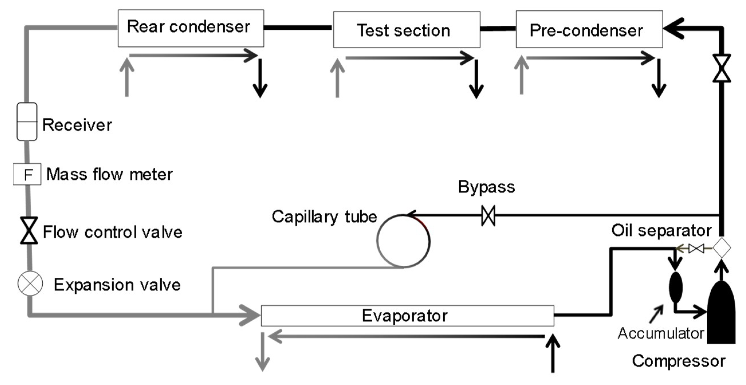
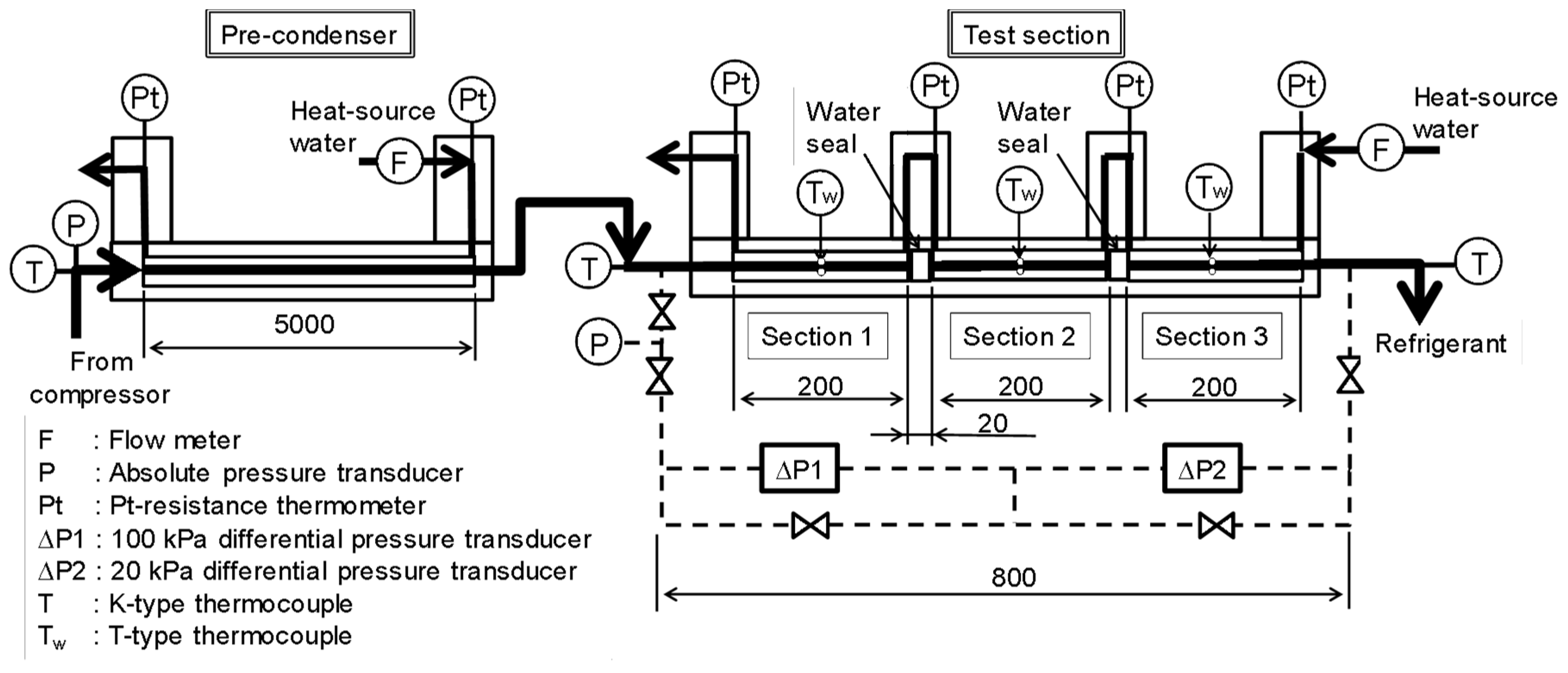
2. Experimental Setup and Procedure

A schematic of the experimental setup is shown in Figure 1, a vapor compression heat pump system consisting of a refrigerant loop and four heat-source water loops. The refrigerant loop consists of a compressor, oil separator, pre-condenser, test section, rear condenser, liquid receiver, mass flow meter, expansion valve, and evaporator. Each heat-source water loop consists of a water tank, temperature control unit, water pump, and flow meters. The refrigerant flow rate is adjusted by the expansion valve, bypass valve, and rotational speed of the compressor.
Details of the pre-condenser and test section are shown in Figure 2 for measurements using R1234ze(E), which is a double-tube heat exchanger consisting of three subsections with a length of 200 mm. In each subsection, a test tube is cooled by water passing through the annulus, while the refrigerant flows within the inner tube. Measurement lengths for the pressure drop and heat transfer are 800 mm and 200 mm, respectively. Therefore, the test section for the measurements using R32, R410A, and R152a, was different from that of R1234ze(E), and it was shown in a published paper [13]. The device measurement accuracies were shown in Table 1, and the reliability of the experimental loop confirmed that heat balance is consistent, with a 10% difference between the refrigerant and heat-source water side.
The test copper tube used a smooth tube, with an outer diameter of 4.02 mm and an inner diameter of 3.48 mm. In the experimental setup, the pressure and the thermal equilibrium vapor quality of inlet No.1 subsection are changed to steady values by the pre-condenser, and the condensation process of refrigerant progresses from the No.1 to the No.3 subsection.
Under experimental conditions, the refrigerant mass velocity varied from 100 to 400 kg m−2s−1, and the saturation temperature at the inlet test section was maintained at 35 °C. The amount of quality change, which depended on the refrigerant, mass velocity, and heat flux, in each subsection, was approximately 0.2 on average, with a maximum of 0.35 for R410A in mass velocity of 100 kg m−2s−1. The physical properties of used refrigerants in this study are shown in Table 2.

3. Method of Experimental Data Analysis

In each subsection, the frictional pressure drop during the condensation process Δ P F is defined as follows:
Δ P F = Δ P Δ P M ,
where Δ P is the measured pressure drop of the refrigerant through each subsection, and Δ P M is the acceleration pressure drop. The acceleration pressure drop, Δ P M , is calculated by Equation (2).
Δ P M = Δ { G 2 x 2 ξ ρ V + G 2 ( 1 x ) 2 ( 1 ξ ) ρ L }
In Equation (2), ξ is a void fraction, G is the refrigerant mass velocity, and x is the vapor quality. The thermodynamic and transport properties of the refrigerants and heat-source water were found from REFPROP Ver. 9.1 [14]. The void fraction ξ could be used from the below Equation (3), as proposed by Smith [15] in the smooth tube.
ξ = [ 1 + ρ V ρ L ( 1 x x ) ( 0.4 + 0.6 ρ L ρ V + 0.4 1 x x 1 + 0.4 1 x x ) ] 1
The local thermal equilibrium quality for each subsection xn is defined as follows:
x n = h n h L n h Vn h Ln ,
where hVn and hLn are the enthalpies of liquid and vapor in the saturation state, and hn is the local enthalpy of each subsection. hVn and hLn are found by the saturated pressure of each subsection. The local enthalpy of No. 1 subsection center is determined as follows:
h 1 = h pre Q cpre m r Q c 1 m r × 1 2 ,
where hpre is the enthalpy of the superheated vapor at the inlet of the pre-condenser, and Qpre and Qc1 are the heat transfer rates in the pre-condenser and No. 1 subsection, respectively. mr is the refrigerant flow rate; hpre is found by the measured pressure and temperature at the inlet mixing chamber of pre-condenser, while the local enthalpy of the No. n subsection center, after the second subsection, is found as follows:
h n = h n 1 Q cn m r × 1 2 .
The condensation heat transfer coefficient α is defined as
α = Q c / { π d i L ( T r T wi ) } ,
where Qc is the heat transfer rate in each subsection, obtained from the heat balance of the heat-source water flowing inside the annulus; L is the effective heat transfer length, and di is the inner diameter of the tube. Twi is the arithmetic mean temperature of the tube’s inner wall surface. Tr was found by the measured refrigerant pressure, and Twi was calculated from the measured temperature of the tube’s outside wall surface from a one-dimensional thermal conductivity equation.
T wi = T wo + Q c ln ( d o / d i ) / ( 2 π λ w L ) ,
where do is the outside diameter of the tube, and λw is the thermal conductivity of the tube.

4. Results and Discussion

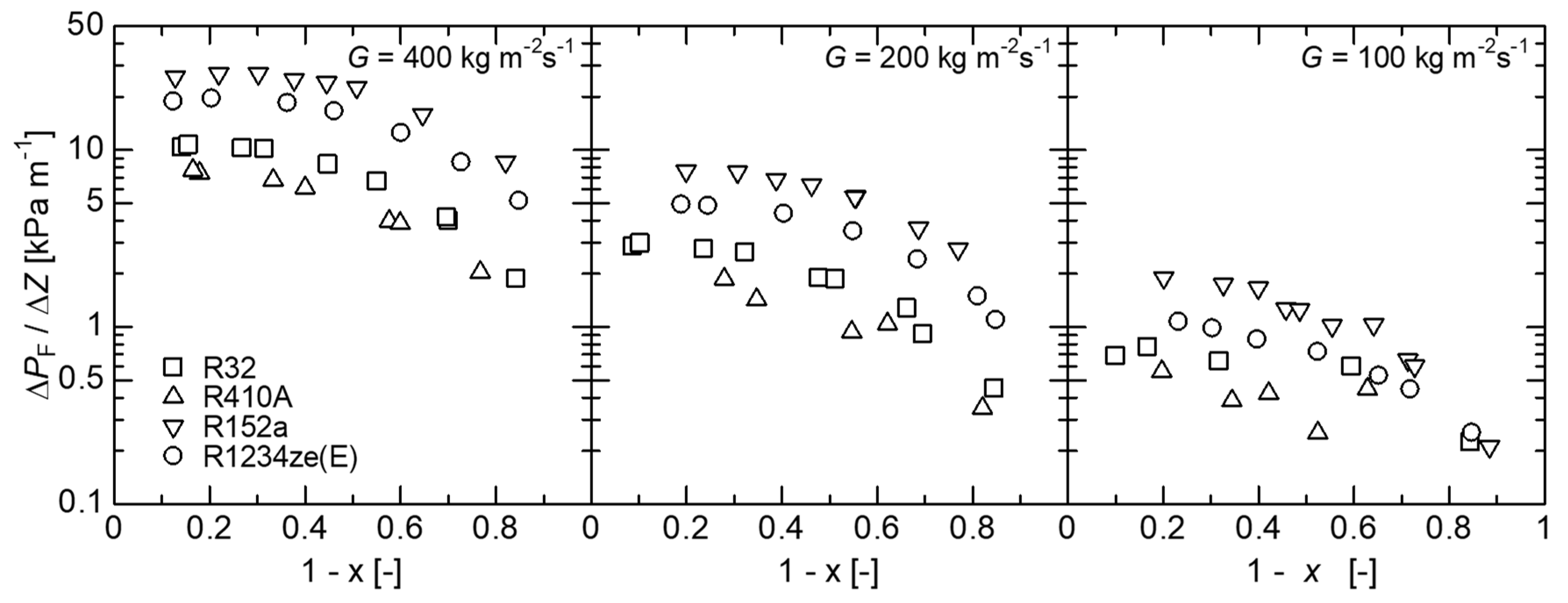
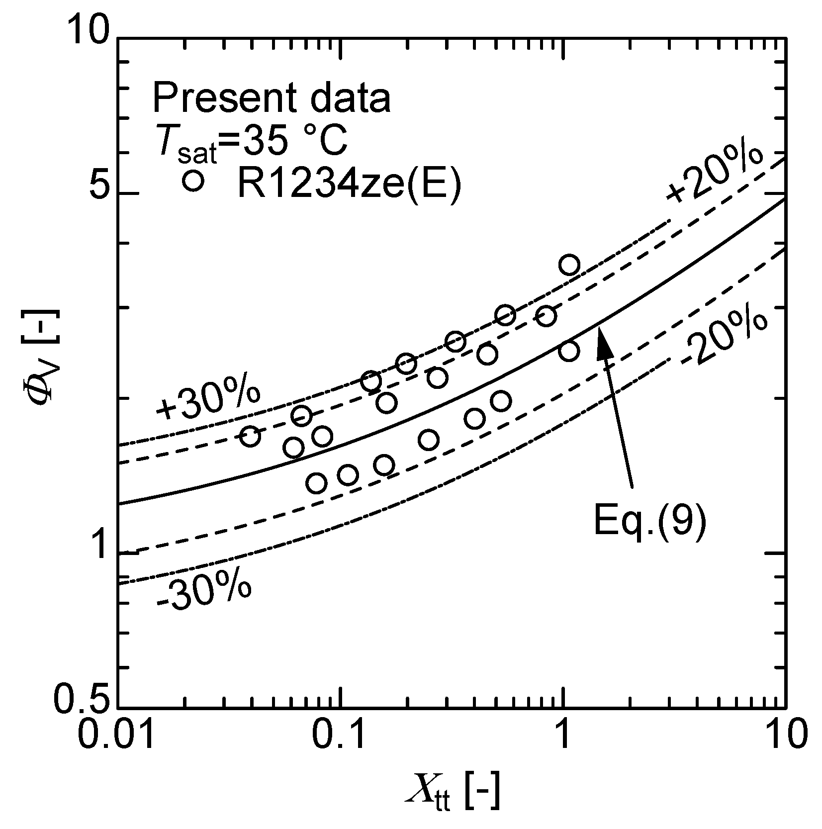
4.1. Pressure Drop in a Smooth Tube

Figure 3 shows the relationship for R1234ze(E) between the frictional pressure drop Δ P F / Δ Z and the wetness 1 − x for the mass velocities of 400, 200, and 100 kg m−2s−1. As shown in the figure, the frictional pressure drop decreases as mass velocity decreases, and it decreases as vapor velocity and wall shear stress decrease, as condensation proceeds. The comparison of results for different refrigerants shows that the frictional pressure drop of R410A is lower than that of other refrigerants, under most conditions. The second lowest is that of R32, and the highest is that of R152a. The frictional pressure drop of R1234ze(E) was shown to be lower than that of R152a, and higher than that of R32.
Figure 4 shows the present data of R1234ze(E) as the relationship between Φ V and Χ tt . The experimental results of R1234ze(E) can be correlated to approximately ±30% by Equation (11), proposed by Hirose et al. [12], with a two-phase pressure drop multiplier Φ V based on the obtained R32, R410A, and R152a of smooth and microfin tubes.
Φ V = 1 + 1.55 X tt 0.4 ,
where the Lockhart–Martinelli parameter, Χ tt , and the two-phase pressure drop multiplier, Φ V , are respectively defined as
Χ tt = { ( 1 x ) / x } 0.9 ( ρ V / ρ L ) 0.5 ( μ L / μ V ) 0.1 ,
Φ V = ( Δ P F / Δ Z ) / ( Δ P V / Δ Z ) ,
where Δ P F / Δ Z is the frictional pressure drop of the vapor/liquid two-phase flow, ( Δ P V / Δ Z ) is the frictional pressure drop when the vapor component flows alone inside a tube, and can be found by the following equation:
( Δ P V / Δ Z ) = 2 f V G 2 x 2 / ( ρ V d i ) ,
where the friction factors f V were provided by Inoue and Ichinose [11], for a single-phase flow inside a 4 mm outside smooth tube, as follows:
f V = 0.26 R e V 0.38 ,
where R e V is the vapor Reynolds number of the refrigerant, and is defined as follows:
R e V = G x d i / μ V .

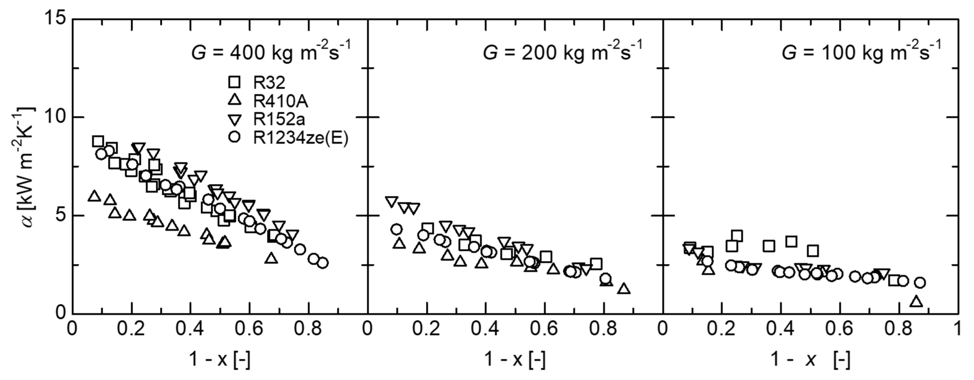
4.2. Condensation Heat Transfer Coefficient

Figure 5 shows the relationship of R1234ze(E) between the condensation heat transfer coefficient α, and the wetness 1 − x at the mass velocities of 400, 200, and 100 kg m−2s−1. From the results, the heat transfer coefficient of R1234ze(E) is lower than that of R152a, as well as that of R32, R410A, and R152a. The heat transfer coefficient decreased as wetness increased, because the heat transfer resistance of the liquid film increased as condensation proceeded. Additionally, the forced convection condensation decreased as the refrigerant vapor velocity decreased. A comparison of the results for different refrigerants shows that the heat transfer coefficient of R152a is higher than those of other refrigerants, under most conditions. Moreover, the heat transfer coefficient of R1234ze(E) is lower than that of R152a, as well as that of R32, R410A, and R152a.
Figure 6a–d show the comparison of experimental values, including R1234ze(E), to values estimated from previous correlations, Haraguchi et al. [2], Dobson and Chato [3], Cavallini et al. [4] and Son and Lee [7], respectively. The Haraguchi et al. correlation, shown in Figure 6a, overestimates the experimental values by up to 80%. However, the predicted trends agree with the measured values. The Dobson and Chato correlation, shown in Figure 6b, overestimates the experimental values by up to 80%. However, the predicted trends agree with the measured values. Figure 6c shows that the experimental values and the values predicted by the Cavallini et al. correlation can be correlated within ±30%. Figure 6d shows that the Son and Lee correlation overestimates the experimental values by up to 150%.

4.3. Derivation of the General Correlation for Condensation Heat Transfer in Small-Diameter Smooth Tube

From Figure 6, it is found that the experimental values for the small-diameter smooth tube could not be correlated with sufficiently high accuracy, and could not be easily predicted by using the existing correlation. Therefore, we tried to derive an empirical correlation to predict the heat transfer coefficients, for many types of refrigerants, based on the Haraguchi et al. [2] correlation. In their correlation, Haraguchi et al. defined the Nu number as
N u = ( N u F a + N u B a ) 1 a ,
where NuF is the forced convection condensation Nusselt number, and NuB is the free convection condensation Nusselt number. Solliman’s modified Froude number F r so was used to distinguish the wavy flow and annular flow pattern in the small-diameter smooth tube. Dobson and Chato [3] have reported that the flow is annular when F r so > 20 , and wavy when F r so < 20 , based on their experimental results for a small-diameter smooth tube. The Solliman’s modified Froude number F r so is found by
F r so = 0.025 R e L 1.59 { ( 1 + 1.09 χ tt 0.039 ) / χ tt } 1.5 / G a 0.5 ( R e L 1250 ) ,
F r so = 1.26 R e L 1.04 { ( 1 + 1.09 χ tt 0.039 ) / χ tt } 1.5 / G a 0.5 ( R e L > 1250 ) ,
where R e L is the liquid Reynolds number of the refrigerant, and is defined as follows:
R e L = { G ( 1 x ) d i } / μ L ,
where it conducts the optimization of the free convection condensation Nusselt number NuB, which is wavy when F r so < 20 , as follows:
N u B = 0.297   B o 0.11 H ( ξ ) ( G a P r L / P h L ) 0.25 ,
where H ( ξ ) and a void fraction ξ are found by Equations (20) and (8).
H ( ξ ) = ξ + { 10 ( 1 ξ ) 0.1 10 + 1.7 × 10 4 R e L } ξ ( 1 ξ )
NuF is defined as
N u F = 0.5 f V R e L Φ V ( ρ L / ρ V ) 0.5 { x / ( 1 x ) } ( P r L / T i * ) ,
where Φ V and fV are the friction factor and the two-phase pressure drop multiplier from Equations (11) and (13), respectively. (Pr/Ti*) is obtained from the following equation, by using the Nusselt number Nu from Equation (23).
( P r L / T i * ) = ( N u a N u B a ) 1 a 0.5 f V R e L Φ V ( ρ L / ρ V ) 0.5 { x / ( 1 x ) } ,
N u = α d i / λ L ,
where λ L is the thermal conductivity of the refrigerant.
Figure 7a shows the relationship between (Pr/Ti*) and ReL at the annular flow area ( F r so > 20 ). The following correlations were finally obtained within ±30%, then, the minimal error between the experimental and predicted values was lowest by a = 5.
( P r L / T i * ) = 0.24 R e L 0.13   ( F r so > 20 )
The new correlation of forced convection Nusselt number NuF for the annular flow area ( F r so > 20 ) was obtained from Equations (21) and (24), as follows:
N u F = 0.17 f V ( Φ V / Χ tt ) ( μ L / μ V ) 0.1 { x / ( 1 x ) } 0.1 R e L 0.87 .
The correlation between the new equations and the measured data for a small-diameter smooth tube was shown in Figure 7b. From this, it is found that the new general correlation agrees well with the measured data of R32, R410A, and R152a, within approximately ±30%.
The comparison of results for R1234ze(E) for the small-diameter smooth tube was shown in Figure 8a. The predicted trend agrees with the measured values of R1234ze(E); however, the predicted value underestimates the experimental values by approximately −30%, particularly in the low wetness range. This is caused by the difference between the thermodynamic and transport properties of R1234ze(E), which is one of the low-pressure refrigerants, with the other refrigerants, which have an effect on condensation heat transfer. Figure 8b shows the comparison between the experimental data of Longo et al. [16] and the present correlation for R404A and R290. The figure shows that the trends in the entire wetness region generally agree within ±30%; it was found that the present correlation can be applied to R404A and R290 refrigerants.

5. Conclusions

The experiments to obtain data on the condensation heat transfer coefficient and frictional pressure drop, by using a 4 mm outside diameter smooth tube and R32, R152a, R410A, and R1234ze(E) as test refrigerants, were conducted in this paper. Additionally, the new general correlation of the condensation heat transfer, for broad application on small-diameter smooth tube and several kinds of refrigerants, was proposed. The results are as follows:
(1)
The frictional pressure drop of R1234ze(E) can be correlated within ±30% by our previous general correlation of frictional pressure drop for the small-diameter smooth tube.
(2)
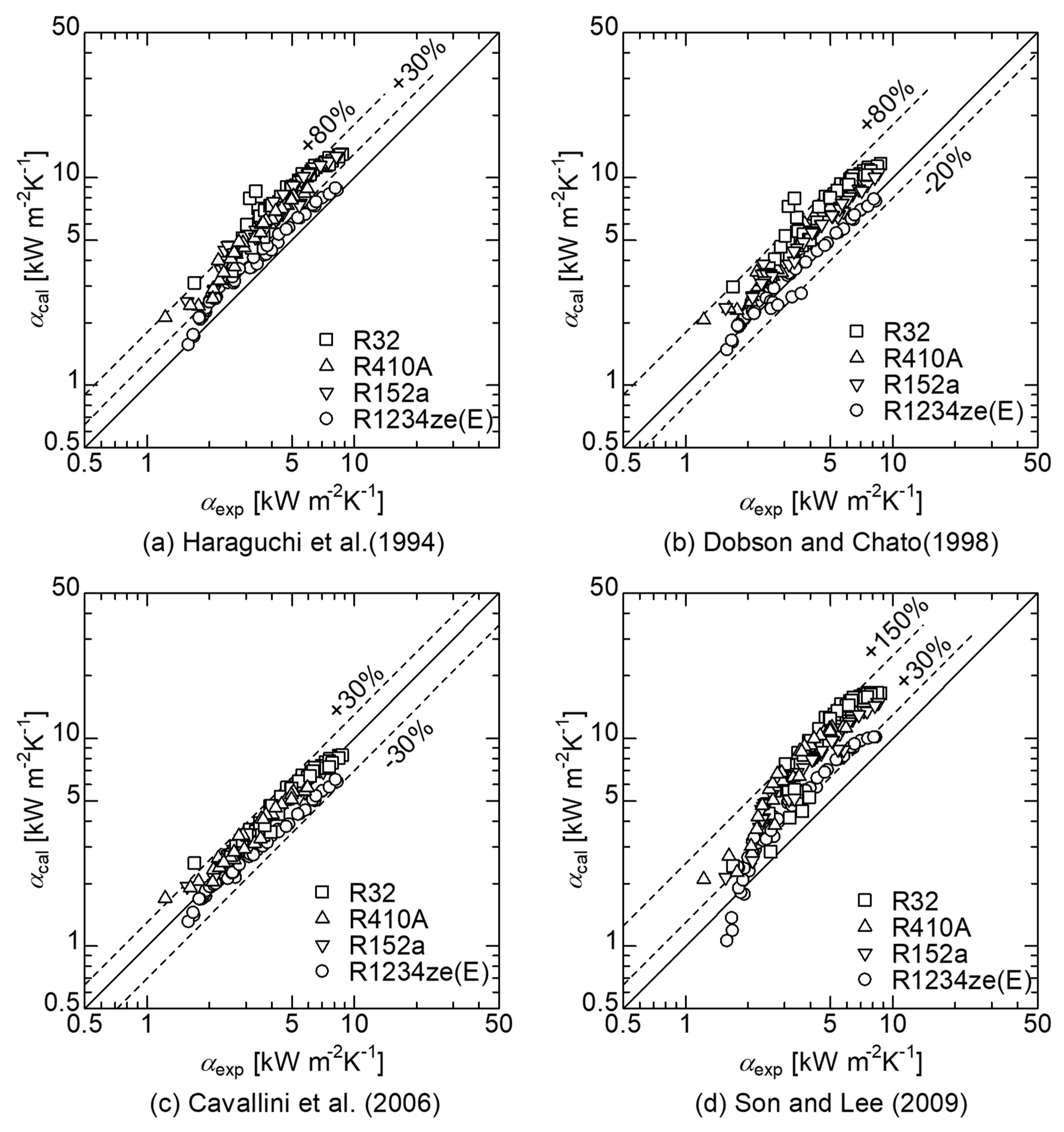
For small-diameter smooth tubes, the condensation heat transfer coefficient can be predicted within ±30% by the correlation of Cavallini et al., which has the highest accuracy among the previously proposed correlations.
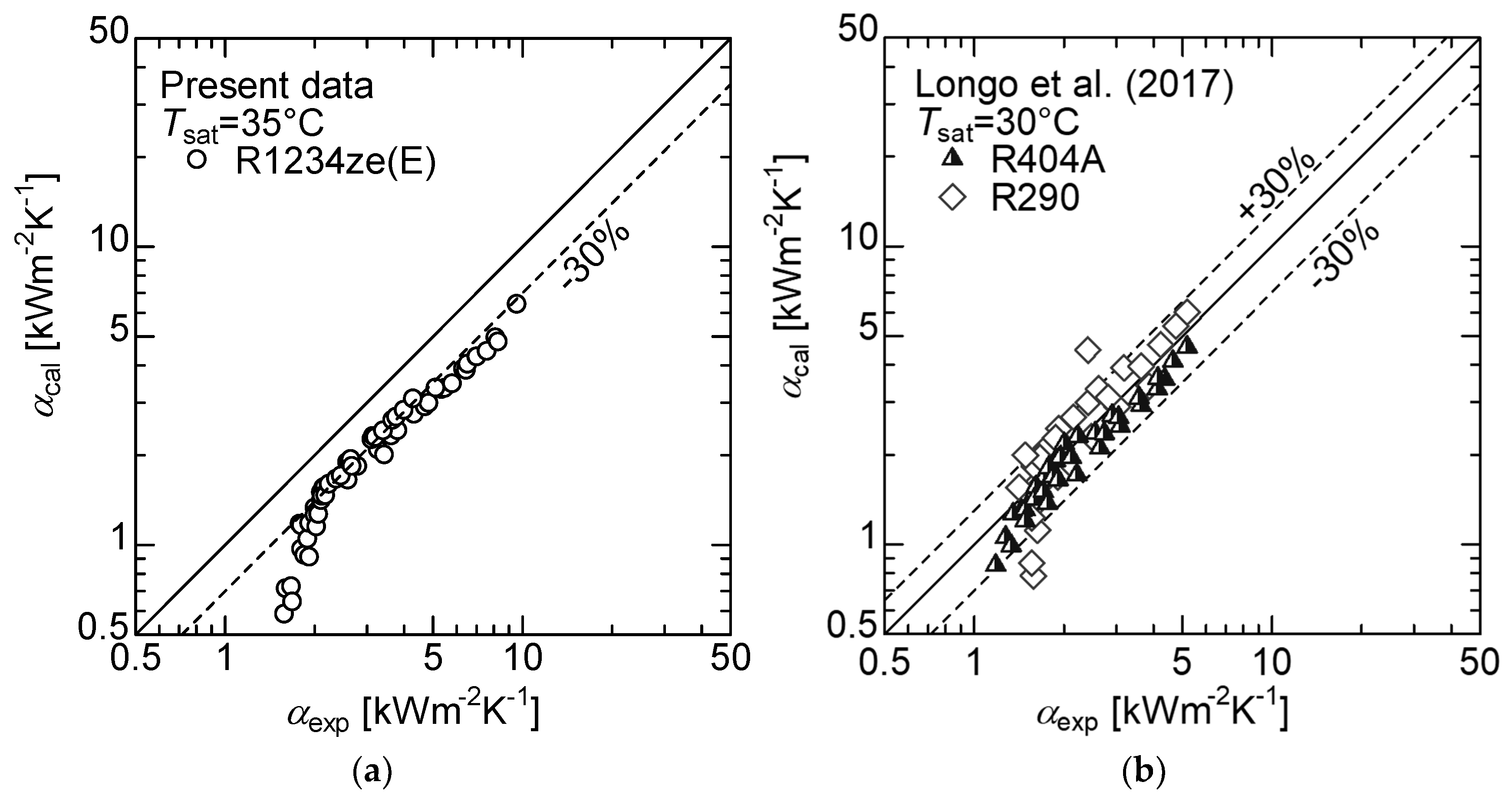
(3)
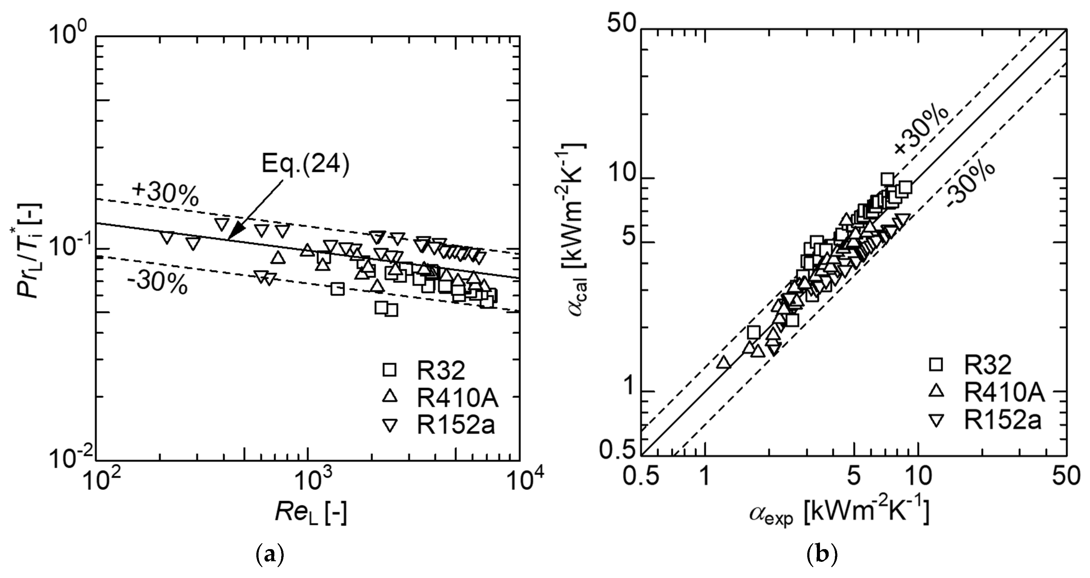
A new general correlation, by a simple and convenient method for estimating the condensation heat transfer for small-diameter smooth tubes and several kinds of refrigerants, was proposed. The predicted trend agrees with the measured values of R1234ze(E); however, the predicted value underestimates the experimental values by approximately −30%, particularly in the low wetness region.

Author Contributions

N.I. conducted this project, wrote the paper and instructed the experimental analysis. M.H. and J.I. designed, built and operated the experimental setup and performed the experimental analysis. D.J. operated the experimental setup and corrected the calculation of experimental analysis and paper formatting.

Funding

This study was supported by the Research & Development Section, Technical Department, Kobelco & Material Copper Tube Ltd., and assisted during the experiment by Kouhei Fujima (Graduate School student).

Acknowledgments

We would like to express our gratitude for the support provided.

Conflicts of Interest

The authors declare no conflicts of interest.

Nomenclature

Aheat transfer area (m2)
BoBond number = ( ρ L ρ V ) g d i / σ
cPisobaric specific heat (J kg−1 K−1)
dtube diameter (m)
ffriction factor
FrSOSolliman’s modified Froude number
Grefrigerant mass velocity (kg m−2s−1)
ggravitational acceleration (m s−2)
GaGalileo number = g d i 3 ρ L 2 / μ L 2
hfglatent heat of condensation (J kg−1)
Lheat transfer length (m)
mmass flow rate (kg s−1)
NuNusselt number = α d i / λ L
NuBfree convection Nusselt number
NuFforced convection Nusselt number
Ppressure (Pa)
Phphase change number = c P ( T r T wi ) / h f g
PrPrandtl number = ( c P μ ) / λ
Qheat transfer rate of each subsection (W)
ReLliquid Reynolds number = G ( 1 x ) d i / μ L
ReVvapor Reynolds number = G x d i / μ V
Ttemperature (K)
Ti*dimensionless temperature difference
xvapor quality
Greek Symbols
αheat transfer coefficient (W m−2 K−1)
Δ P total pressure drop (Pa)
Δ P F frictional pressure drop (Pa)
Δ P M acceleration pressure drop (Pa)
λthermal conductivity (W m−1 K−1)
μviscosity (Pa s)
ξvoid fraction
ρdensity (kg m−3)
Φtwo-phase pressure drop multiplier
Χ tt Lockhart–Martinelli parameter
Subscripts
calcalculated value
cheat-source water
expexperiment
iinside
Lliquid
nsubsection number
ooutside
prepre-condenser
rrefrigerant
satsaturated
soSoliman
Vvapor
Wwall

References

  1. Haraguchi, H.; Koyama, S.; Fujii, T. Condensation of Refrigerants HCFC22, HFC134a and HCFC123 in a Horizontal Smooth Tube: 1st Report, Proposals of Empirical Expressions for Local Pressure Drop. J. Jpn. Soc. Mech. Eng. 1994, 60, 239–244. (In Japanese) [Google Scholar]
  2. Haraguchi, H.; Koyama, S.; Fujii, T. Condensation of Refrigerants HCFC22, HFC134a and HCFC123 in a Horizontal Smooth tube: 2nd report, Proposals of Empirical Expressions for Local Heat Transfer Coefficient. J. Jpn. Soc. Mech. Eng. 1994, 60, 245–252. (In Japanese) [Google Scholar]
  3. Dobson, M.; Chato, J. Condensation in Smooth Horizontal Tubes. J. Heat Transf. 1998, 120, 193–213. [Google Scholar] [CrossRef]
  4. Cavallini, A.; Del Col, D.; Doretti, L.; Matkovic, M.; Rossetto, L.; Zilio, C. Condensation in Horizontal Smooth Tubes: A New Heat Transfer Model for heat Exchanger Design. Heat Transf. Eng. 2006, 27–28, 31–38. [Google Scholar] [CrossRef]
  5. Hossain, M.A.; Onaka, Y.; Miyara, A. Experimental Study on Condensation Heat Transfer and Pressure drop in Horizontal Smooth Tube for R1234ze(E), R32 and R410A. Int. J. Refrig. 2012, 35, 927–938. [Google Scholar] [CrossRef]
  6. Han, B.; Liu, F.; Cai, D.; Tian, Q.; He, G. Experimental Study on Condensation Heat Transfer of R32/R290 Mixture in Horizontal Tubes. Appl. Therm. Eng. 2015. [Google Scholar] [CrossRef]
  7. Son, C.; Lee, H. Condensation Heat Transfer Characteristics of R-22, R-134a and R-410A in Small Diameter Tubes. Heat Mass Transf. 2009, 45, 1153–1166. [Google Scholar] [CrossRef]
  8. Matsumoto, T.; Arata, Y.; Miyata, K.; Hamamoto, Y.; Mori, H. Experiment on Condensation Heat Transfer of HFC134a in a Horizontal Single Rectangular Mini-channel. In Proceedings of the 9th Asian Conference on Refrigeration and Air-conditioning 2018, Sapporo, Japan, 10–13 June 2018. [Google Scholar]
  9. Longo, G.A.; Mancin, S.; Righetti, G.; Zilio, C. R134a and Its Low GWP Substitutes R1234yf and R1234ze(E) Condensation inside a 4 mm Horizontal Smooth Tube. In Proceedings of the 17th International Refrigeration and Air Conditioning Conference at Purdue 2018, West Lafayette, IN, USA, 9–12 July 2018. [Google Scholar]
  10. Longo, G.A.; Mancin, S.; Righetti, G.; Zilio, C. R410A and Its Low GWP Substitutes R32 Condensation inside a 4 mm Horizontal Smooth Tube. In Proceedings of the 16th International Heat Transfer Conference 2018, Beijing, China, 10–15 August 2018. [Google Scholar]
  11. Inoue, N.; Ichinose, J. Single-phase Heat Transfer and Pressure Drop inside Internally Helical-grooved Horizontal Small-diameter Tubes. Int. J. Air-Cond. Refrig. 2012, 20. [Google Scholar] [CrossRef]
  12. Ichinose, J.; Inoue, N. The Condensation Heat Transfer and Pressure Drop of R410A and R32 inside Horizontal Small-diameter Tubes-2nd Report: Empirical Correlation for Condensation Heat Transfer and Pressure Drop. Trans. JSRAE 2011, 28, 479–490. (In Japanese) [Google Scholar]
  13. Hirose, M.; Ichinose, J.; Inoue, N. Development of the general correlation for condensation heat transfer and pressure drop inside horizontal 4 mm small-diameter smooth and microfin tubes. Int. J. Refrig. 2018, 90, 238–248. [Google Scholar] [CrossRef]
  14. Lemmon, E.W.; Huber, M.L.; McLinden, M.O. NIST Standard Reference Database 23, Reference Fluid Thermodynamic and Transport Properties REFPROP Ver. 9.1; National Institute of Standards and Technology: Gaithersburg, MD, USA, 2013. [Google Scholar]
  15. Smith, S.L. Void Fractions in Two-Phase Flow: A Correlation Based upon an Equal Velocity Head Model. Proc. Inst. Mech. Eng. 1969, 184, 647–664. [Google Scholar] [CrossRef]
  16. Longo, G.A.; Mancin, S.; Righetti, G.; Zilio, C. Saturated vapour condensation of HFC404A inside a 4 mm ID horizontal smooth tube: Comparison with the long-term low GWP substitutes HC290 (Propane) and HC1270 (Propylene). Int. J. Heat Mass Transf. 2017, 108, 2088–2099. [Google Scholar] [CrossRef]
Figure 1. Schematic of the experimental setup.
Applsci 08 02267 g001
Figure 2. Details of the pre-condenser and test section.
Applsci 08 02267 g002
Figure 3. Relationship between pressure drop and wetness for the small-diameter smooth tube.
Applsci 08 02267 g003
Figure 4. Comparison of pressure drop between that predicted by Hirose et al. correlation and R1234ze(E).
Applsci 08 02267 g004
Figure 5. Relationship between condensation heat transfer and wetness for the small-diameter smooth tube.
Applsci 08 02267 g005
Figure 6. Comparison of measured and predicted heat transfer coefficient values.
Applsci 08 02267 g006
Figure 7. (a) Relationship between relative temperature difference and liquid Reynolds number in R32, 410A. (b) Heat transfer coefficient correlation between that predicted by the present correlation, and the measured values of R32, R410A, and R152a.
Applsci 08 02267 g007
Figure 8. (a) Comparison of the heat transfer coefficient between that predicted by the present correlation, and the measured values of R1234ze(E). (b) Comparison of heat transfer coefficient between that predicted by present correlation, and data from Longo at al. for R404A and R290.
Applsci 08 02267 g008
Table 1. Measurement accuracies of the measuring devices.
InstrumentFull ScaleUncertainty
T-type thermocouple-0.05 K
Coriolis mass flow meter43 kg h−10.2%
Absolute pressure transducer3 MPa±0.3 kPa
Differential pressure transducer100 kPa±0.2 kPa
Differential pressure transduscer20 kPa±0.04 kPa
Pt-resistance thermometer-±0.04 K
Volumetric flow meter500 L h−1±0.01 L h−1
Table 2. Physical properties of used refrigerants at saturation state temperature 35 °C.
R410AR32R152aR1234ze(E)R404AR290
Global Warming Potential*1924677138<139423
Pressure (MPa)2.142.190.790.671.611.22
Dew point temp. (°C)35.035.035.035.035.035
Boiling point temp. (°C)34.934.6
Vapor density (kg m−3)88.963.324.635.387.526.6
Liquid density (kg m−3)1005917.1873.41129995.0476.1
Vapor viscosity (μPa s)14.513.510.512.712.58.7
Liquid viscosity (μPa s)103.2101.0145.3177.2119.487.4
Vapor thermal cond. (mW m−1 K−1)17.717.216.114.517.720.5
Liquid thermal cond. (mW m−1 K−1)83.6118.393.870.960.089.1
Latent heat (kJ kg−1)169249267159128317

